Fluidwell F010-U User Manual
Flowrate indicator
Hide thumbs
Also See for F010-U:
- Operation manual (36 pages) ,
- Manual (44 pages) ,
- User manual (48 pages)

Related Manuals for Fluidwell F010-U


Summary of Contents for Fluidwell F010-U
- Page 1 User Manual F010-U FLOWRATE INDICATOR Signal input: 0-10 V flowmeter signal Options: intrinsically safe backlight F-Series - Field mounted indicators for safe and hazardous areas More info: www.fluidwell.com/fseries...
-
Page 2: Table Of Contents
Menu 4: Flowmeter ......................14 5.4.5 Menu 5: Others ......................15 INSTALLATION........................16 Installation / environmental conditions ................16 Handling the F010-U enclosure ..................17 6.2.1 Identification........................17 6.2.2 Opening, assembling and closing the F-Series .............. 18 Mechanical installation....................20 6.3.1... - Page 3 7.3.1 Power supply ........................35 7.3.2 Sensor supply ......................... 35 Configuration examples Intrinsically Safe applications ........... 36 7.4.1 F010-U-PD-XI-ZB - Ex ia IIC/IIIC..................36 MAINTENANCE........................37 General directions......................37 Instructions for repair ...................... 37 Battery replacement......................38 8.3.1 Safety instructions ......................38 8.3.2...
-
Page 4: About This Manual
● incorrect functioning of the unit or connected instruments. A note informs you of important information. WARRANTY AND TECHNICAL SUPPORT For warranty and technical support on your Fluidwell products, visit our internet site www.fluidwell.com or contact us at support@fluidwell.com. MODEL REFERENCE Hardware version: 03.03.xx... -
Page 5: Safety
F010-U User Manual SAFETY PERSONAL SAFETY ● Explosion hazard: Never open the unit when explosive atmosphere is present, and the unit is connected to a power supply or consuming device like the internal battery supply. ● Risk of electric shock: Only open the unit if all leads are free of potential electrical energy. -
Page 6: Introduction
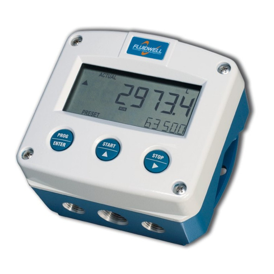
Fig. 1: The F010 This manual describes the daily use, configuration and installation of the F010-U with analog 0-10 V input from a flowmeter and its available options. The following figure shows the F010-U used in a typical application. -
Page 7: Options
● Panel mount enclosure (Types HB, HC) ● Flame-proof enclosure (Type XF) ● Display backlight (Type ZB). INSTALLATION EXAMPLE Following parts can be recognized in below installation example. Fig. 3: Installation example F010-U 1. Front cover 3. Label 5. Keys 2. Display 4. Back cover 6. -
Page 8: Operation
Section 2: Safety [»5] INTRODUCTION This chapter describes the daily use and operation of the F010-U. For this, the F-Series is equipped with a control panel that provides the operator with various functions, information and operating modes. 4.1.1... -
Page 9: Backlight (Type Zb)
F010-U User Manual Normally, the display is updated depending on the refresh rate selected in the configuration settings. By pressing any key, the display switches to refreshing the information 8 times per second. After 30 seconds of key inactivity, the display returns to the configured refresh rate. -
Page 10: Configuration
INTRODUCTION This chapter describes how technicians can use configuration settings to configure the F-Series for optimal functionality. Configuration of the F010-U can be done in SETUP mode, using the front keys. CONFIGURING USING SETUP MODE For an overview of Operating modes, see Section 4.1.1: Operating modes [»8]... -
Page 11: Changing Configuration Settings
F010-U User Manual 5.2.3 CHANGING CONFIGURATION SETTINGS A menu item either contains a value (a number with optionally a decimal point and sign, e.g. -123.45) or a selection list (e.g. L – m - USGAL). After a menu item is selected in the SETUP menu, a new value can be programmed by performing the following steps. -
Page 12: Setup Menu Overview
User Manual F010-U SETUP MENU OVERVIEW FLOW RATE DEFAULT UNIT mL - L - m3 - mg - g - kg - ton - GAL - bbl - lb - cf - REV - no unit - scf - Nm3 - NL - P... -
Page 13: Menu 2: Display
● 3.1: POWER MANAGEMENT > LCD UPDATE set to 1sec: 5 years. ● 3.1: POWER MANAGEMENT > LCD UPDATE The F010-U has two main modes: operational and shelf mode. In shelf BATTERY MODE mode the product can be stored for several years with extremely low power consumption from the battery. -
Page 14: Menu 4: Flowmeter
5.4.4 MENU 4: FLOWMETER FLOWMETER FORMULA The F010-U can process the analog 0 - 10 V signal in two ways: linear or as a root. Interpolation: the signal is processed in a linear way ● R = S x I Square root: the signal is processed applying a square root, f.i. -
Page 15: Menu 5: Others
F010-U User Manual FLOWMETER CALIBRATE LOW The unit is calibrated in factory using a very accurate voltage source. In case the flowmeter signal does not equal 0 V at flow rate zero, this function is needed to set the minimum input voltage at flow rate zero. -
Page 16: Installation
Personnel must read and understand this Operating Manual before carrying out its instructions. ● The F010-U may only be operated by personnel who are authorized and trained by the operator of the facility. All instructions in this manual are to be observed. -
Page 17: Handling The F010-U Enclosure
F010-U User Manual HANDLING THE F010-U ENCLOSURE 6.2.1 IDENTIFICATION The F-Series can be supplied as suitable for Safe Area or Hazardous Area. Suitability for Intrinsic Safety is indicated in the model Type XI. Refer to for identification and installation labels Section 7: Intrinsically safe applications [»30]... -
Page 18: Opening, Assembling And Closing The F-Series
User Manual F010-U Fig. 9: Example of F0-Series installation label (Safe Area - Type PM or PF) Serial number and year of production The serial number can be reviewed on the identification label, the installation label, or in . The production SETUP 5.3: OTHERS >... - Page 19 F010-U User Manual Closing / replacing the cover 1. Re-insert all terminals to their original position. 2. Carefully position the front cover onto the back cover, making sure that the gasket falls nicely into the gutter of the back cover.
-
Page 20: Mechanical Installation
User Manual F010-U MECHANICAL INSTALLATION 6.3.1 MECHANICAL DIMENSIONS Aluminum and stainless steel enclosures 75 mm (2.95") 90 mm (3.54") 130 mm (5.12") 112 mm (4.40") 12mm 12mm 30 mm 30 mm 30mm 30mm M16 x 1,5 M16 x 1,5 M20 x 1,5... - Page 21 F010-U User Manual Non-metallic enclosures 75 mm (2.95") 130 mm (5.12") 112 mm (4.40") HK back box: (flat bottom) 75 mm (2.95") 118 mm (4.65”) 25mm 25mm D=20mm D=20mm 12mm 12mm 30mm 30mm 24mm 24mm D=12mm D=16mm D=16mm D=20mm 36mm 36mm 0.12”...
-
Page 22: Mounting The F-Series
User Manual F010-U 6.3.2 MOUNTING THE F-SERIES The enclosure can be installed by itself or with the aid of a mounting plate in the configurations shown below. When the product is installed on a wall or onto a meter, please use components and installation techniques that are suitable for the used materials. -
Page 23: Electrical Installation
● The wire screens shall be terminated at one side to prevent wire loops. Inside of the F010-U, the different common ground terminals are connected to each other. It is advised, as illustrated, to terminate the wire screens in the vicinity of the sensor and to insulate the wire screen with a shrink tube at the F010-U side. -
Page 24: Field Wiring Connections
F010-U Connecting Protective Earth to a non-metallic enclosure When the F010-U is supplied with a non-metal enclosure (e.g. plastic), the field mount enclosure meets the requirements of class 2 (double insulated). Therefore any incoming PE conductor can be terminated with an insulating end cap. -
Page 25: Power Supply
C22.2 No. 61010-1 / UL61010-1 / EN/IEC 61010-1. The F010-U can be powered from an external power supply. For Type PX or PD, an optional internal power supply is also available in the form of a lithium battery (Type PB). When both external and internal power supplies are available, the internal power supply is interrupted and will act as a backup supply. -
Page 26: Terminal Connectors Safe Area Applications - Type Px, Pd
6.5.1 TERMINALS 1-2 (6): FLOWMETER INPUT The F010-U requires a 0-10V flowmeter signal which will be processed 4 times per second with 16 bit accuracy. The input is not isolated. The screen of the signal wire can be connected to the common ground terminal (see Section 6.4.3:... -
Page 27: Terminals 4-5: Power Supply - Type Px And Pd
TERMINALS 4-5: POWER SUPPLY - TYPE PX AND PD To power the F010-U a 8-30V DC (type PX) or 16-30V DC (type PD) power supply can be applied. Connect the "-" to terminal 4 and the "+" to terminal 5. -
Page 28: Terminal Connectors Safe Area Applications - Type Pf, Pm
Overview of terminal connectors - Type PF or PM 6.6.1 TERMINALS GND-1-2: POWER SUPPLY To power the F010-U with a power supply option of type PF or type PM, connect a suitable power supply to the terminals as indicated in below table. Note: NC is not connected. -
Page 29: Terminals 5-7: Flowmeter Input
6.6.2 TERMINALS 5-7: FLOWMETER INPUT The F010-U requires a 0-10V flowmeter signal which will be processed 4 times per second with 16 bit accuracy. The input is not isolated. The screen of the signal wire can be connected to the common ground terminal (see Section 6.4.3:... -
Page 30: Intrinsically Safe Applications
User Manual F010-U INTRINSICALLY SAFE APPLICATIONS IDENTIFICATION The F0-Series can be supplied as suitable for Safe Area or Hazardous Area. Suitability for Intrinsic Safety is indicated in the model Type XI. If Type XI is not indicated your unit is not suitable for Intrinsically Safe applications! -
Page 31: Electrical Installation In Hazardous Areas
Personnel must read and understand this Operating Manual before carrying out its instructions. ● The F010-U may only be operated by personnel who are authorized and trained by the operator of the facility. All instructions in this manual are to be observed. -
Page 32: Electrical Data - Control Drawing
User Manual F010-U 7.2.2 ELECTRICAL DATA - CONTROL DRAWING trol Dr ing F -U-XI Ce t r ific t a ion F0-SERIES – Type -XI T RMINAL CONNE CTORS F0 ERIE c mm on ground Ce tif r ica e number: CSA.08.2059461... -
Page 33: Installations Based On Atex Or Iecex Certificate
F010-U User Manual 7.2.3 INSTALLATIONS BASED ON ATEX OR IECEX CERTIFICATE Installation instructions ● For installation under ATEX directive: this Intrinsically Safe device must be installed in accordance with ATEX directive 2014/34/EU and product certificate KEMA 03ATEX1168 X. ● For installation under IECEx scheme: this Intrinsically Safe device must be installed in accordance with product certificate IECEx DEK 08.0006X. -
Page 34: Electrical Data - Annex 1
User Manual F010-U 7.2.4 ELECTRICAL DATA - ANNEX 1 Annex 1 ( mo el p s eci fic) to prod uct certif c i ates KEMA 03ATEX1168 X, IECEx DEK 08. 00 6X Model F0..-U-XI Int nal supply for use w... -
Page 35: Terminal Connectors Hazardous Area Applications
7.3.1 POWER SUPPLY The F010-U can be powered from an external power supply. For Types PX or PD, an optional internal power supply is also available in the form of an intrinsically safe lithium primary battery (Type PC). When both external and internal power supplies are available, the internal power supply is interrupted and will serve as a backup supply. -
Page 36: Configuration Examples Intrinsically Safe Applications
Sensor supply voltage terminal 6 same as input voltage terminal 5. Please note: Type PD may be used in combination with the battery (Type PC). PD will power the F010-U, the battery will be disabled automatically until the power is disconnected Page 36... -
Page 37: Maintenance
Personnel must read and understand this Operating Manual before carrying out its instructions. ● The F010-U may only be operated by personnel who are authorized and trained by the operator of the facility. All instructions in this manual are to be observed. -
Page 38: Battery Replacement
User Manual F010-U BATTERY REPLACEMENT 8.3.1 SAFETY INSTRUCTIONS ● Handle the battery with the utmost care to prevent a short circuit and damage. A mistreated battery can become unsafe. Unsafe batteries can cause serious injury. Do not recharge, crush, disassemble, incinerate, heat above its rated temperature or expose the contents to water. -
Page 39: Battery Replacement Procedure
F010-U User Manual 8.3.2 BATTERY REPLACEMENT PROCEDURE Before starting the battery replacement procedure, make sure that the marking on the new battery corresponds with the type of installation, as shown in Section 8.3.1: Safety instructions [»38] When used in Intrinsically Safe applications - Type PC: The hook-and-loop fastener that holds the battery is antistatic and thus fit for Hazardous Area use. -
Page 40: Appendix A - Technical Specification
User Manual F010-U APPENDIX A - TECHNICAL SPECIFICATION GENERAL DISPLAY Type High intensity reflective numeric and alphanumeric LCD, UV-resistant Digits 5½ with height 26mm (1”) and 11 with height 8mm (0.31”). Various symbols and measuring units. Dimensions 90 x 40 mm (3.5” x 1.6”) - Page 41 F010-U User Manual POWER REQUIREMENTS Type PB SAFE AREA ONLY - Standard lithium primary battery. Life up to 5 years. Type PC INTRINSICALLY SAFE - Certified lithium primary battery. Life up to 5 years. Type PD 16-30 V DC. Max power consumption 1 W.
-
Page 42: Input
User Manual F010-U INPUT FLOWMETER Signal type 0-10 V, with signal calibration feature Accuracy 16 bit. Error < 0.01 mA or ±0.05% FS. Low-level cut-off programmable. Span 0.000010 - 199,999 with variable decimal position. Update time Four times per second Voltage drop Max 1 V DC @ 20 mA. -
Page 43: Appendix B - Troubleshooting
APPENDIX B - TROUBLESHOOTING Table 1 lists and describes how to troubleshoot problems that can occur when installing or operating the F010-U. Table 2 lists internal alarm codes and conditions signaled by a blinking ALARM flag on the display ). Press the SELECT key several times to display the 4-digit error code shown in Table 2. -
Page 44: Appendix C - Legal Information
DECLARATIONS OF CONFORMITY EU De cla tio n of Conformi Fluidwell F0‒Series indicators he , February 2022 We, Fluidwell BV, declare under our s e ol respons ibility that the F0 ‒Series indicators are de igne d and will operate conform the following applicable European... - Page 45 F010-U User Manual LIST OF CONFIGURATION SETTINGS SETTING DEFAULT DATE: DATE: FLOW RATE UNIT TIME UNIT DECIMALS SPAN 1600 DISPLAY BARGRAPH BACKLIGHT BACKLIGHT BRIGHTNESS POWER MANAGEMENT LCD UPDATE 1 sec BATTERY MODE operational FLOWMETER FORMULA interpolation FILTER 01 (off) CUT-OFF...
- Page 46 User Manual F010-U NOTES Page 46 FW_F010-U_M_v0501-01_EN...
- Page 47 F010-U User Manual FW_F010-U_M_v0501-01_EN Page 47...
- Page 48 Fluidwell bv P.O. Box 6 Voltaweg 23 Website: www.fluidwell.com 5460 AA Veghel 5466 AZ Veghel Find your nearest representative: www.fluidwell.com/representatives the Netherlands the Netherlands © Copyright 2022 - FW_F010-U_M_v0501-01_EN...
Need help?
Do you have a question about the F010-U and is the answer not in the manual?
Questions and answers