
Related Manuals for CommScope WCS-4


Summarization of Contents
Document Overview
Document Revision History
Details changes in the tenth release of the installation guide.
Document Cautions and Notes
Explains icons used for cautions, warnings, and notes in the document.
ERA System Overview
Central Area Node (CAN)
Server-level control and primary signal distribution for ERA systems.
Wide-Area Integration Node (WIN)
Interfaces between Switching CAN and RF sources for C-RAN.
Transport Expansion Node (TEN)
Secondary distribution node connecting to CAN via fiber.
Access Point (AP)
Connects CAN or TEN to antennas or wireless devices.
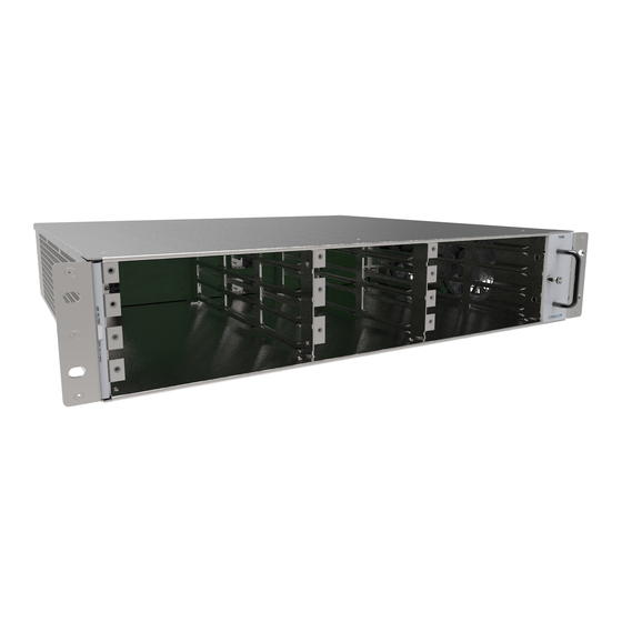
WCS Subrack Slot and Card Assignments
Slot and Card Assignment Rules for Classic CANs
Card installation rules for WCS-4/WCS-2 configured as Classic CAN.
Slot and Card Assignment Rules for Switching CANs
Card installation rules for WCS-4/WCS-2 configured as Switching CAN.
Slot and Card Assignment Rules for WINs
Card installation rules for WCS-4/WCS-2 configured as WIN.
Slot and Card Assignment Rules for TENs
Card installation rules for WCS-4/WCS-2 configured as TEN.
WCS Subrack Cards
System User Interface (SUI) Card
Provides local and LAN Ethernet connections and a USB port.
RF Donor (RFD) Card and RF Donor (RFD) HB Card
Interfaces for RF signals between CAN/WIN and RF source.
Optical Transport (OPT) Card
Provides 10 Gbps fiber connection between CANs, TENs, and WINs.
Copper Transport (CAT) Card
Provides power and 10 Gbps data over Cat6A cables to Access Points.
Auxiliary Unit Transport (AUT) Card
Provides 1 Gbps pass-through connection for Ethernet devices.
CPRI Digital Donor Card
Provides digital CPRI interface between Nokia BBU and WCS Subrack.
Power Supply Unit Subrack and Rectifier Modules
Power Supply Unit Subrack
Houses 12 Vdc and 57 Vdc Rectifier Modules for powering ERA components.
12 Vdc Rectifier Module
Supplies 12 Vdc power to WCS and e-POI Subracks; fully redundant.
57 Vdc Power Rectifier Module
Supplies power over Cat6A to UAPs, Copper CAP Ls, and connected devices.
Maximum Number of APs that can be Powered by WCS Subrack
ERA Software Power Estimates
Estimates AP power consumption for CAT6A powering calculations.
CAT Cards
Defines number of UAPs and Copper CAP Ls powered by CAT Card versions.
WCS Subracks, 57 Vdc Rectifier Modules, and Service Voltage
Number of APs by Original WCS Subracks
Lists UAPs and CAP Ls powered by original WCS Subracks and 57Vdc modules.
Number of APs by Current WCS Subracks
Lists UAPs and CAP Ls powered by current WCS Subracks and 57Vdc modules.
APs in a Mixed Copper CAP L and UAP System
Original WCS/CAT Card AP Support
Shows AP support for original WCS/CAT cards with 2x 57Vdc PSU.
Current WCS/CAT Card AP Support
Shows AP support for current WCS/CAT cards with 2x 57Vdc PSU.
Optional e-POI Subracks
Interface Card (IFC)
Sets Subrack number, provides status and alarms for e-POI Modules.
e-POI Modules
Provide interface and attenuation for ERA RFD Cards; hot swappable.
Safely Working with ERA Hardware
Health and Safety Precautions
Essential ground connection, laser radiation, and RF radiation warnings.
Property Damage Warnings
Operating instructions, license holders, warning labels, and correct settings.
General Installation Safety Requirements
Electro-Static Discharge (ESD) Protection
Wear ESD wrist strap to prevent component damage from static discharge.
Compliance (FCC RF exposure)
Antenna selection and installation for FCC RF exposure compliance.
FCC/ISED Requirements Notices
European EN50385 Exposure Limits
Power Density limits for European EN50385 compliance.
FCC/ISED Device Operation
Notices regarding FCC part 15 rules and Health Canada safety.
Additional Safety Notices
Overvoltage Category and Surge Protection
Complies with Overvoltage Category II; additional protection recommended.
Class B/A Digital Device Compliance
Compliance with FCC Class B and Class A digital device limits.
Equipment Symbols and Compliance
Compliance Labels
Meanings of symbols for FCC, ISED, CE, and CE 0700 compliance.
Install Subracks and PSU in Equipment Rack
WCS Subrack Type Considerations
Installation requirements for standard and -48Vdc WCS subracks.
Unpack and Inspect Components
Procedures for inspecting and handling subracks and components upon arrival.
Rack-Mount WCS-2 and WCS-4 Subracks and PSU
Mounting Requirements
Firewall, air space, support rails, and PSU placement rules.
Rack-Mount -48Vdc WCS Subracks
Mounting Requirements for -48Vdc
Firewall, air space, and support rail rules for -48Vdc WCS subracks.
Connect -48Vdc WCS Rear-panel Cables
-48Vdc WCS Rear Panel Cabling Diagram
Shows power and communication cable connections for -48Vdc WCS.
Install a Subrack Card
Subrack Card Installation Procedure
Steps for installing cards into WCS subracks, including PEM screw and support knob.
Connect the SUI Card
SUI Card Connectivity
Connecting WCS Subrack to laptop, LAN, or modem via Local and LAN2 ports.
Connect the RFD Cards
RFD Card Connections
Connecting RF cables to QMA connectors for SISO and MIMO services.
Connect the OPT Cards
Fiber Optic Link Budget
Factors affecting fiber link performance: power, sensitivity, length, wavelength, splices.
Minimum Optical Path Loss
Optical power must be less than receiver overload threshold.
Maximum Optical Path Loss
Received optical power must be greater than receiver sensitivity.
Optical Link Loss Calculation
Minimum Performance Levels
Minimum performance specifications for fiber optic components.
SFP+ Modules Tested for ERA
Install SFP+ Modules in OPT Cards
Steps to install 10 Gbps SFP+ Modules into OPT Card ports.
Cabling OPT Cards: WIN to Switching CAN
WIN to Switching CAN Connection Steps
Connects WIN to Switching CAN using SFP+ Modules and fiber cable.
Cabling OPT Cards: TEN to Classic CAN
TEN to Classic CAN Connection Steps
Connects TEN to Classic CAN using SFP+ Modules and fiber cable.
Cabling OPT Cards: TEN to Switching CAN
TEN to Switching CAN Connection Steps
Connects TEN to Switching CAN using SFP+ Modules and fiber cable.
Cabling OPT Cards for Fiber AP Connection
OPT Card to Fiber AP Connection
Connects OPT Card in CAN/TEN to a Fiber AP using SFP+ Modules.
Connect the CAT Cards
CAT Card to AP Connection
Connects APs to CAT Card using Cat6A cables in Classic CAN or TEN.
Connect the AUT Cards
AUT Card Ethernet Connectivity
Connects Ethernet devices to APs via AUT Card; notes on bandwidth and Loss of Service.
Connect the CDD Cards
Calculate CDD Card Power Draw
Calculates power draw for CDD Cards based on number installed (40 Watts each).
Connect CDD Card to BBU
Connects CDD Card to Nokia AirScale ABIA Module using fiber optic cable.
WCS Subrack Filter Module Maintenance
Removing a Filter Module
Procedure for removing WCS Subrack Filter Modules without screws.
Cleaning and Installing WCS Subrack Filter Modules
Cleaning Filter Modules
Reusable filter modules can be cleaned with brush, vacuum, or water.
Installing Filter Modules
Procedure for sliding and pressing cleaned or new filter modules into slots.
Remove e-POI Module from e-POI Subrack
e-POI Module Removal Procedure
Steps to remove e-POI module and ensure ERA software updates.
Cat6A Specifications and Testing Requirements
Cat6A Performance Standards
Cat6A U/UTP performance standards defined by TIA/EIA 568 C.2.
Contacting CommScope
CMS Global Technical Support
Contact information for CommScope Mobility Solutions Technical Support.
Telephone Helplines
Helpline numbers for live support in US, Canada, and EMEA.
Online Support
How to initiate a Technical Support ticket via CommScope's website.
Hardware to Software Mapping and Training
Hardware to Software Mapping
Document listing minimum software requirements for ERA hardware.
Technical Training
Accessing CommScope University training courses.
Accessing ERA User Documentation
How to access ERA user documentation on CommScope DCCS Customer Portal.
Need help?
Do you have a question about the WCS-4 and is the answer not in the manual?
Questions and answers