Sign In
Upload
Download
Table of Contents
Contents
Add to my manuals
Delete from my manuals
Share
URL of this page:
HTML Link:
Bookmark this page
Add
Manual will be automatically added to "My Manuals"
Print this page
×
Bookmark added
×
Added to my manuals
Manuals
Brands
SICK Manuals
Industrial Equipment
ATM90
Commissioning instructions
SICK ATM90 Commissioning Instructions
Hide thumbs
1
2
Table Of Contents
3
4
5
6
7
8
9
10
11
12
13
14
15
16
17
18
19
20
21
22
23
24
25
26
27
28
29
30
31
32
33
34
35
36
37
38
39
40
41
42
43
44
45
46
47
48
49
50
51
52
53
54
55
56
57
58
59
60
61
62
63
64
65
66
67
68
69
70
71
72
73
74
page
of
74
Go
/
74
Contents
Table of Contents
Bookmarks
Table of Contents
Table of Contents
Contents
Schedule of Revisions
Introduction
Using These Commissioning Instructions
Documentation
Definition of the Symbols Used in the Document
Conformity
Profibus
European Union Directive Compliance
Designations and Abbreviations
Profibus DP-Specific
Data Type Specifications
Encoder-Specific
Safety Precautions
Responsibilities of the Commissioning Staff
Validity and Application
Authorised Users
Safety Guidelines and Personal Protection
Encoder Safety Precautions for Installation, Operation and Maintenance
Introduction
Profibus Standardisation
Profibus DP
Figure 4-1: Protocol Architecture
DP-V0 Communication Protocol
Figure 4-2: Master/Slave Principle of the SRD Service
Physical Profibus Network Link
Network Topology
RS485 Transmission Technology
Installation Notes Re: RS485
Figure 4-3: Topology of Profibus DP
Profibus Cabling for RS485
Figure 4-5: Cabling (9-Pin D-Sub Connector) and Bus Termination
Cable Screening
Device Profiles
Further Information
Encoder Modes
Cyclical Data Transmission
Parameterisation
Configuration
I/O Data Transmission
Specification of the Encoder Data
Encoder Parameters/Attributes
General Conditions for Using the Scaling Function
Specification for Using the Encoder in "Continuous Mode
Case A) Scaling Function Without Limitation to the Measuring Range (with Offset)
Case B) Adapted Scaling Functions (Without Offset)
Data Storage
Encoder Attributes/Parameters
Fundamental Explanations
Counting Direction/Code Sequence
Scaling Function Control -- [SFC]
Measuring Units Per Revolution -- [CPR]
Total Measuring Range in Measuring Units -- [CMR]
Position Value
Preset Value
Data Assemblies/Data Components
Position Value
Speed Value
Time Stamp
Preset Value
Device Integration/Projecting
System Requirements
Description
Figure 7-1: Device Integration
Data Mapping of a UINT32 (UDINT) Value
Figure 7-2: GSD Implementation
Use of the 'COM Profibus' Configuration Tool
Module Configuration
Figure 7-3: Module Configuration
Parameter Settings - Rotary Encoders
Figure 7-4: Parameter Data - Operating Mode
Figure 7-5: Parameter Data - Scaling
Parameter Settings - Linear Encoders
Figure 7-6: Parameter Data - Operating Mode
Figure 7-7: Parameter Data - Scaling
System Configuration
Master-Slave Communication
Figure 8-1: DP State Machine
Stipulations/Definitions
Parametrisation
DP-Specific Standard Data
Device-Specific Data
Operating Mode
Code Sequence
Class 2 Functionality
Commissioning Diagnostics Control
Scaling Function
Enabling the SSA Service
Selection of the Address Setting
Measuring Units Per Revolution -- [CPR]
Total Measuring Range -- [CMR]
Configuration
Cyclical Data Traffic (Data Exchange Mode)
Ddlm_Data_Exchange. - Data Assembly (A1). - Module IN_04
Ddlm_Data_Exchange. - Data Assembly (A2). - Modul IO_04
Ddlm_Data_Exchange. - Data Assembly (A3). - Modul IN_06
Ddlm_Data_Exchange. - Data Assembly (A4). - Modul IO_06
Ddlm_Data_Exchange. - Data Assembly (A5). - Modul IN_08
Ddlm_Data_Exchange. - Data Assembly (A6). - Module IO_08
Diagnostic Information
Evaluation at Control Level
Diagnostic Messages
Standard Diagnostics
Status-1
Status-2
Status-3
Master Address
Device-Specific Diagnostics - Class 1
Class 1 Diagnostic Data - Overview
Diagnostic Header
Alarms
Commissioning Diagnostics Alarm
EEPROM Memory Error
Error in the Position Value
Error Correction Measures
Operating Status
Device Identification
Physical Resolution Span (PRS)
Physical Number of Revolutions (Pnumr)
Device-Specific Diagnostics - Class 2
Class 2 Diagnostic Data - Overview
Diagnostic Header
Additional Alarms
Supported Alarms
Warnings
Supported Warnings
Profile Version
Software Version
Operating Time
Offset Value
Counts Per Revolution -- [CPR]
Number of Counts Per Measuring Range -- [CMR]
Serial Number
Manufacturer-Specific Diagnostics (Manufacturer Class)
Station Address
Encoder Status
DP Controller Status
Encoder - Mounting and Connection
Mounting
Screening
Screen Connection at the Bus Link Adapter with Cable Fitting ATM60-P/ATM90-P/ KHK53-P
Figure 10-1: Screen Connection at the Bus Link Adapter with Cable ATM60-P/ATM90-P/ KHK53-P
Screen Connection at the Bus Link Adapter with Screw-In System ATM90-P
Figure 10-2: Screen Connection with Screw-In System ATM90-P
Connection to the Network
Installation Notes Re: Voltage Supply
ATM 60 with Bus Link Adapter - Cable Fitting
Figure 10-3: Pinout ATM 60 with Bus Link Adapter - Cable Fitting
ATM 60 with Bus Link Adapter - Screw-In System M12
Figure 10-4: Pinout ATM 60 Direct with Bus Link Adapter - Screw-In System M12
ATM 90 with Bus Link Adapter - Cable Fitting
Figure 10-5: Pinout ATM 90 with Bus Link Adapter
ATM 90 with Screw-In System M14 - Without Bus Link Adapter
Figure 10-6: Pinout ATM 90 Direct with Screw-In System M14 - Without Bus Link Adapter
Linear Encoder KHK53 with Bus Link Adapter - Cable Fitting
Device Handling in the Network
Figure 10-7: Pinout Linear Encoder KHK53 with Bus Link Adapter
Figure 10-8: Device Handling in the Network 'ATM 60' (DIP Switch in the Bus Link Adapter)
Figure 10-9: Device Handling in the Network 'ATM 90' (Aperture for DIP Switch in the Encoder)
Address Setting
Figure 10-10: Device Handling in the Network 'KHK53' (DIP Switch in the Bus Link Adapter)
Figure 10-11: DIP Switch S1 Setting
Counting Direction
Preset Function
Bus Termination
Status/Display Information
Technical Description
Description of the Rotary Encoders
Description of the Linear Encoder
Profibus Interface - Brief Overview of Specific Features
Profibus Interface - Specification
List of Figures
Notes
Advertisement
Quick Links
Download this manual
SICK AG
Erwin-Sick-Str. 1 ·
D-79183 Waldkirch
Commissioning Instructions
ATM60 / ATM90 / KHK53
with Profibus DP Interface to EN 50170 Vol. 2
Commissioning Instructions 8013512
Jan 2005
Table of
Contents
Previous
Page
Next
Page
1
2
3
4
5
Advertisement
Table of Contents
Need help?
Do you have a question about the ATM90 and is the answer not in the manual?
Ask a question
Questions and answers
Related Manuals for SICK ATM90
Industrial Equipment SICK ATM60 Commissioning Instructions
(74 pages)
Industrial Equipment SICK Gas Cell AGK848 Installation Operation & Maintenance
(36 pages)
Industrial Equipment SICK KTS-WB41141142ZZZZ Quick Start Manual
Contrasttasters (8 pages)
Industrial Equipment SICK MCS100FT Operating Instructions Manual
Ftir multicomponent analysis system for continuous flue gas monitoring (106 pages)
Industrial Equipment SICK SIM2500 Operating Instructions Manual
Sensor integration machine (44 pages)
Industrial Equipment SICK HIPERFACE DSL Technical Information
Implementation (172 pages)
Industrial Equipment SICK SKS36S Operating Manual
Safe motor feedback systems (25 pages)
Industrial Equipment SICK EDS35-2 Series Operating Instructions Manual
Safe motor feedback systems (90 pages)
Industrial Equipment SICK KTS-WB81141142ZZZZ Quick Start Manual
(9 pages)
Industrial Equipment SICK C4000 Operating Instructions Manual
Clone plug (11 pages)
Industrial Equipment SICK SIM1000 FXA Operating Instructions Manual
Sensor integration machine (34 pages)
Industrial Equipment SICK RFU63 Series Operating Instructions Manual
Rfid read/write device (uhf) (128 pages)
Industrial Equipment SICK VMS4100 Operating Instructions Manual
Track and trace systems (108 pages)
Industrial Equipment SICK TTK50S Operating Instructions Manual
Safe motor feedback systems (27 pages)
Industrial Equipment SICK GLS621 Operating Instructions Manual
Grid localization (56 pages)
Industrial Equipment SICK TPS Operating Instructions Manual
Driver assistance system (90 pages)
Summarization of Contents
1 Introduction
1.1 Using these Commissioning Instructions
Guide on how to use the commissioning instructions for encoders and Profibus network.
1.2 Documentation Overview
Lists the complete documentation components for the encoders.
1.3 Document Symbols Explained
Explains symbols used to highlight important information and warnings.
1.4 Conformity and Standards
Details Profibus standards and EU/UK directive compliance.
2 Designations and Abbreviations
2.1 Profibus DP-Specific Terms
Defines Profibus DP-specific terms and acronyms used in the document.
2.2 Data Type Specifications
Lists and explains various data types used in Profibus communication.
2.3 Encoder-Specific Terms
Defines terms and parameters specific to the encoders.
3 Safety Precautions
3.1 Responsibilities of Commissioning Staff
Outlines the duties and responsibilities of personnel involved in commissioning.
3.2 Validity and Application Guidelines
Specifies the intended use and general safety requirements for the encoders.
3.3 Authorised Users Qualifications
Specifies the qualifications required for personnel performing installation and maintenance.
3.4 Safety Guidelines and Personal Protection
Provides general safety guidelines and personal protection measures during operation.
3.5 Encoder Safety Precautions
Details specific safety measures for fitting, operating, and maintaining the encoders.
4 Profibus Introduction and Standards
4.1 Profibus Standardisation Overview
Explains the basis of Profibus standards and its protocol architecture.
4.2 Profibus DP and Protocols
Overview of Profibus DP and its V0 protocol for data exchange.
4.3 Physical Profibus Network Link and Cabling
Details physical connection, topology, RS485, and cabling requirements.
4.4 Device Profiles and Further Information
Device profiles for interoperability and additional resources list.
5 Encoder Modes
5.1 Cyclical Data Transmission Phases
Explains the three phases of data transmission between master and encoder.
5.2 Encoder Data Specification
Details the data types and assemblies supported by the encoder.
6 Encoder Parameters and Scaling
6.1 Scaling Function Conditions
Conditions and methods for using encoder scaling functions.
6.2 Data Storage and Core Parameters
How parameters are stored and fundamental explanations for key attributes.
6.3 Key Encoder Parameters
Control, CPR, CMR, Position Value, and Preset Value parameters.
6.4 Data Assemblies and Components
Details supported data components like position, speed, and time stamp.
7 Device Integration and Projecting
7.1 System Requirements for Integration
Lists requirements for integrating a Profibus DP slave into a system.
7.2 GSD File Description
Explains the GSD file's role in device integration and data exchange.
7.3 UDINT Value Data Mapping
Details how UDINT values are mapped for parameterization.
7.4 Configuration Tool Usage
Using the COM Profibus tool for module and parameter configuration.
8 System Configuration and Parametrisation
8.1 Master-Slave Communication Flow
Explains the communication flow between master and slave devices.
8.2 Data Definitions and Parametrisation Basics
Defines terms and covers standard/device-specific data for parametrisation.
8.3 Encoder Operating Modes and Settings
Details operating modes, diagnostics, scaling, and address settings.
8.4 Configuration and Data Exchange
Configuration of telegram formats and cyclical data traffic.
9 Diagnostic Information
9.1 Diagnostic Evaluation and Messages
How to evaluate and process diagnostic messages from DP slaves.
9.3 Standard Diagnostics Overview
Standard diagnostic data including status bytes and master address.
9.4 Class 1 Device-Specific Diagnostics
Detailed diagnostics for Class 1 devices, including alarms and error correction.
9.5 Class 2 Device-Specific Diagnostics
Advanced diagnostics for Class 2 devices, including alarms, warnings, and controller status.
10 Encoder Mounting and Connection
10.1 Mounting and Screening
General mounting advice and importance of cable screening.
10.2 Bus Link Adapter Screen Connections
Step-by-step guides for screen connection with different adapters.
10.3 Network Connection Details
Connection types, voltage supply, and pinouts for encoders.
10.4 Device Handling and Configuration
Hardware configuration of address, direction, preset, and bus termination.
10.5 Status/Display Information
Information conveyed by the device's LEDs.
11 Technical Description
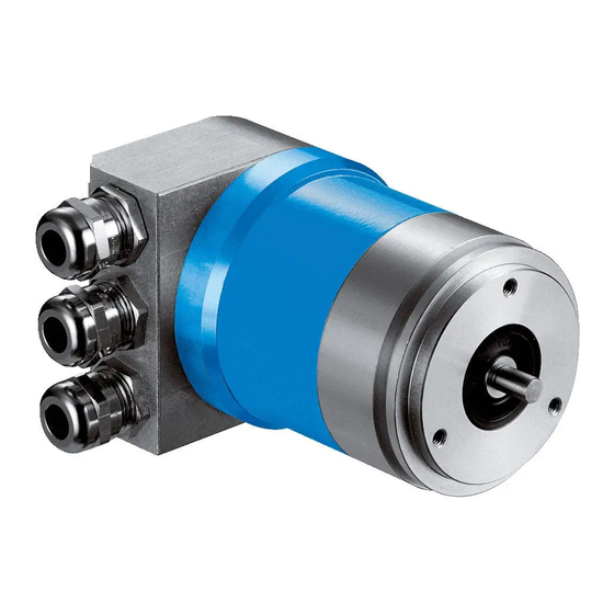
11.1 Rotary Encoder Description
Describes the ATM 60-P/ATM 90-P rotary encoders' features.
11.2 Linear Encoder Description
Describes the KHK53-P linear encoder's features.
11.3 Profibus Interface Features
Summarizes specific features of the Profibus interface.
11.4 Profibus Interface Specification
Provides detailed specifications for the Profibus interface.
Table of Contents
Print
Rename the bookmark
Delete bookmark?
Delete from my manuals?
Login
Sign In
OR
Sign in with Facebook
Sign in with Google
Upload manual
Upload from disk
Upload from URL
Need help?
Do you have a question about the ATM90 and is the answer not in the manual?
Questions and answers