Table of Contents
Advertisement
Quick Links
Advertisement
Chapters
Table of Contents

Subscribe to Our Youtube Channel
Related Manuals for SICK TPS


Summary of Contents for SICK TPS
- Page 1 O P E R A T I N G I N S T R U C T I O N S Driver assistance system...
- Page 2 Operating Instructions This work is protected by copyright. Any rights derived from the copyright shall be reserved for SICK AG. Reproduction of this document or parts of this document is only permissible within the limits of the legal determination of Copyright Law. Alteration or abridgment of the document is not permitted without the explicit written approval of SICK AG.
-
Page 3: Table Of Contents
Connecting the pause signal ................38 5.10 Connecting the RDW lights (optional) ..............39 Commissioning ........................40 Launching the system ..................40 The operator display in configuration mode ............42 Making vehicle setup settings ................43 8021799/2017-09-26 Operating Instructions | SICK Subject to change without notice... - Page 4 .................... 70 8.4.4 Up- and downloading of GPS black spots ........70 8.4.5 Updating TPS software ..............71 Fault diagnosis ........................ 72 Response to faults ....................72 Fault indicators of the LMS151 ................. 72 Typical fault situations during commissioning ..........73 9.3.1...
- Page 5 Tone buzzer dimensional drawing............80 10.3 Tone selection for tone buzzer ................81 11 Figures and tables ......................82 11.1 List of tables ......................82 11.2 List of figures .......................83 11.3 Keywords index ....................85 8021799/2017-09-26 Operating Instructions | SICK Subject to change without notice...
-
Page 6: About These Operating Instructions
Truck Protection System TPS. These operating instructions do not provide information on operating the vehicle into which the TPS is or will be integrated. For information about this instruction, refer to the vehicle's operating instructions. Target group These operating instructions are intended for people who install, connect, commission, operate, and maintain TPS. -
Page 7: Abbreviations Used
Chapter 1 Abbreviations used Truck Protection System = driver assistance system for haul trucks Ladar Digital (Laser Radar) Multi-Layer Range Scanner = 3D LiDAR sensor from SICK AG LD-MRS Laser measurement sensor = 2D LiDAR sensor from SICK AG Road Departure Warning = functionality against unintended road departure... -
Page 8: Safety
NOTE TPS is a driver assistance system. This means that at all times the driver bears the full responsibility for safe operation, in particular for people who are in the hazardous zones of the vehicle. -
Page 9: Intended Use
Chapter 2 Intended use TPS may only be used as described in section 2.2 Applications of the system. It may only be used by qualified personnel in the environment in which it was mounted and initially commissioned by qualified safety personnel in accordance with these operating instructions. -
Page 10: General Safety Notes
2.4.2 General safety notes TPS has been designed in a way that allows for safe operation. However, a certain level of risk will always remain. Awareness of potential sources of danger in the system will help you to work in a safer manner and thus prevent accidents. -
Page 11: Potential Sources Of Danger
EN/IEC 60825-1 (see laser warning label on the device for publication date), 21 CFR 1040.10 and 21 CFR 1040.11. The LMS151 2D LiDAR sensor used by TPS corresponds to laser class 1 (eye safe) as per EN/IEC 60825-1 (see laser warning label on the device for publication date). - Page 12 Cease operation if the cause of the malfunction has not been clearly identified. A defect in the system may result in fatal accidents or damage to the system. Take the TPS out of operation if you cannot clearly identify the fault and if you cannot safely remedy the problem.
-
Page 13: Protection Of The Environment
Dispose of all electronic assemblies as hazardous waste. The electronic assemblies are easy to dismantle. SICK AG does not take back devices that are unusable or irreparable. Note 8021799/2017-09-26 Operating Instructions | SICK... -
Page 14: Product Description
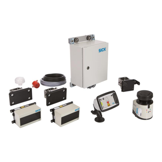
Note Scope of delivery TPS consists of an LMS151 2D LiDAR sensor and two LD-MRS 3D LiDAR sensors, an interactive operator display, a control cabinet, mounting kits with shock mounts and connecting cables, GPS receiver, as well as a tone buzzer. Light signals can be optionally used. -
Page 15: Fig. 2: Laser Output Aperture Of The Ld-Mrs Front And Rear
The operator display is attached to a mounting kit (2) with a swivel connector in the truck, within the operators's field of view. Fig. 4: Operator display with mounting kit 8021799/2017-09-26 Operating Instructions | SICK Subject to change without notice... -
Page 16: Fig. 5: Control Cabinet
A tone buzzer supports the visual warning about an obstacle on the display with an acoustic warning. Fig. 6: Tone buzzer GPS receiver A GPS receiver is used for ego localization in world coordinates, speed, heading and more information. Fig. 7: GPS receiver Operating Instructions | SICK 8021799/2017-09-26 Subject to change without notice... -
Page 17: System Functionality
(black spots) and departure of the road (RDW). During the operation of the truck, the TPS will constantly monitor the surrounding of the vehicle for obstacles. If such an obstacle is detected in one or more of the configured warning zones, the zone violation is reported to the operator visually and audibly. -
Page 18: Rear End Collision Warning
RDW Pause Signal The system provides a pause signal input. The signal is muting the alarm unit for the following 30 seconds. Operating Instructions | SICK 8021799/2017-09-26 Subject to change without notice... -
Page 19: Black Spot Warning
The sound output is automatically turned on again when leaving the black spot area. This function may be used to mute TPS while the truck is in maintenance in a workshop. Note that for the correct function of black spots, GPS must be available. -
Page 20: Status Indicators
OFF: no contamination (optics cover) ON: contamination warning Blinking: contamination error Not used Not used Tab. 2: Status indicators of the LMS151 Operating Instructions | SICK 8021799/2017-09-26 Subject to change without notice... -
Page 21: Fig. 14: The Operator Display In Configuration And Operating Mode
Recommended settings: OFF, ON, ON, OFF, ON (01101) Fig. 15: DIP switch on the tone buzzer Additional information on this can be found in the appendix in chapter 10.3 Tone selection for tone buzzer. 8021799/2017-09-26 Operating Instructions | SICK Subject to change without notice... -
Page 22: Mounting
Operating Instructions Mounting Function test before mounting Before mounting the TPS components on the truck, it is recommended that the functional readiness of the devices should be checked. 1. Place the components on a table. 2. Connect the components according to the wiring diagram (see chapter 5.1 Wiring plan). -
Page 23: Fig. 16: Mounting The Ld-Mrs Using Mounting Kit With Shock Absorber
The supply voltage of the LMS151 RDW must be switched off. Fig. 17: Mounting the LMS151 RDW using mounting kit with shock absorber 8021799/2017-09-26 Operating Instructions | SICK Subject to change without notice... -
Page 24: Fig. 18: Mounting Position Of The Ld-Mrs Hd Front
Fig. 19: Mounting position of the LD-MRS HD Rear The exact angle is defined by its mounting height and will be adjusted during system Note setup. Please avoid unnecessary obstructions. Operating Instructions | SICK 8021799/2017-09-26 Subject to change without notice... -
Page 25: Mounting The Bracket For The Operator Display
The mounting kit is made up of the bracket (1) and an adapter (2) to hold the operator display. Fig. 21: Mounting the operator display 8021799/2017-09-26 Operating Instructions | SICK Subject to change without notice... -
Page 26: Mount The Control Cabinet
It is not intended for outside mounting. Before mounting the control cabinet, check that all components can be reached by the Note supplied cables. Fig. 22: Mounting the control cabinet Operating Instructions | SICK 8021799/2017-09-26 Subject to change without notice... -
Page 27: Mount The Gps Receiver
The recommended place is along the front railing of the truck. Fig. 23: Mounting the GPS receiver Mounting the tone buzzer Mount the tone buzzer in the operator cab behind the driver. Fig. 24: Mounting the tone buzzer 8021799/2017-09-26 Operating Instructions | SICK Subject to change without notice... -
Page 28: Electrical Installation
Operating Instructions Electrical installation HAZARD Disconnect the power to the system Make sure that all TPS components are disconnected from the voltage supply during electrical installation. HAZARD Risk of injury due to electrical current Standard safety requirements must be met when working on electrical systems. -
Page 29: Fig. 26: Tps Wiring Connection Overview (Inside Control Cabinet)
Electrical installation Operating Instructions Chapter 5 Fig. 26: TPS wiring connection overview (inside control cabinet) 8021799/2017-09-26 Operating Instructions | SICK Subject to change without notice... -
Page 30: Connecting The Ld-Mrs Front And Rear Lidar Sensor
1. Connect the round plug-in connector the connecting cable on the LD-MRS to the Power female connector. 2. Run the connecting cable from the 3D LiDAR sensor to the control cabinet. 3. Connect the LD-MRS to the terminal block inside the control cabinet. Operating Instructions | SICK 8021799/2017-09-26 Subject to change without notice... -
Page 31: Connecting The Lms151 Rdw Lidar Sensor
The LMS151 RDW has the following connections: Fig. 30: LMS151 connections Connection Description Power Connection to the voltage supply Data Not assigned Not assigned Ethernet Connection to the network Tab. 5: LMS151 connections 8021799/2017-09-26 Operating Instructions | SICK Subject to change without notice... -
Page 32: Fig. 31: Connecting The Ld-Mrs To The Control Cabinet
1. Screw the M12 round connector into the female Ethernet connector of the 2D LiDAR sensor. 2. Run the Ethernet cable from the 2D LiDAR sensor to the control cabinet. 3. Connect the RJ45 connector into a free port on the Ethernet switch. Operating Instructions | SICK 8021799/2017-09-26 Subject to change without notice... -
Page 33: Connecting The Operator Display
The Ethernet cable for connecting the display and control cabinet has an angled M12 male connector (for connection on the display side) and a RJ45 connector (for connection on the control cabinet). Fig. 34: Connecting the operator display to the control cabinet 8021799/2017-09-26 Operating Instructions | SICK Subject to change without notice... -
Page 34: Fig. 35: Inserting Connecting Cables On The Operator Display
Fig. 36: Mounting the adapter on the operator display 1. Place the adapter on the reverse of the operator display. 2. Secure the adapter to the operator display using the four supplied screws. Operating Instructions | SICK 8021799/2017-09-26 Subject to change without notice... -
Page 35: Fig. 37: Mounting The Adapter With The Operator Display On The Bracket
It is recommended that cable shielding should be used for bundled and safe installation Note of the cables. 2. Connect the RJ45 connector into a free port on the Ethernet switch. 8021799/2017-09-26 Operating Instructions | SICK Subject to change without notice... -
Page 36: Connecting The Gps Receiver
The GND connection is carried out via the blue wire. This is connected to the blue cable wire from the control cabinet. The black wire is not connected. Operating Instructions | SICK 8021799/2017-09-26 Subject to change without notice... -
Page 37: Connecting The Control Cabinet
Place the wires to the voltage supply as follows. Wire color Connection Voltage supply Brown Voltage +24 V Blue Ground Tab. 9: Connecting the control cabinet to the voltage supply 8021799/2017-09-26 Operating Instructions | SICK Subject to change without notice... -
Page 38: Connecting The Reverse Signal (Optional)
Place the wires to the voltage supply as follows. Wire color Connection Voltage supply Brown Voltage +24 V Blue Ground Tab. 11: Connecting the control cabinet to the voltage supply Operating Instructions | SICK 8021799/2017-09-26 Subject to change without notice... -
Page 39: Connecting The Rdw Lights (Optional)
Connection Voltage supply Brown Voltage +24 V Blue Ground Tab. 12: Connecting the control cabinet to the RDW lights Fig. 42: Connecting the control cabinet to the RDW lights (optional) 8021799/2017-09-26 Operating Instructions | SICK Subject to change without notice... -
Page 40: Commissioning
Fig. 44: Information about incomplete configuration Warnings (optical and acoustical) may occur as the system setup is yet to be done. This is Note no malfunction and can be ignored. Operating Instructions | SICK 8021799/2017-09-26 Subject to change without notice... -
Page 41: Fig. 45: Configuration Mode After Launching For The First Time
Start configuration Press OK to confirm you have seen the notification. TPS is started in the configuration mode. An overview page with the individual setup steps is automatically displayed on the operator display. Fig. 45: Configuration mode after launching for the first time Display of the operational readiness of the devices The LMS151 2D LiDAR sensor visualizes operational readiness via the green OK LED (1). -
Page 42: The Operator Display In Configuration Mode
It is only possible for the person carrying out commissioning to switch to the operating mode if all setup steps have been successfully completed and marked with a green check mark. Tab. 13: Functions in the configuration mode Operating Instructions | SICK 8021799/2017-09-26 Subject to change without notice... -
Page 43: Making Vehicle Setup Settings
Enter the truck dimensions in the appropriate places. Please use image shown on the screen for reference. The TPS is scalable and adjustable to different truck sizes and types. Therefore the individual measures of the vehicle have to be configured. -
Page 44: Configuring The Lidar Sensors
As soon as the entries have been completed on one assistant page, use the next icon to navigate to the following page. When changing the assistant page, the settings and information that have been provided are temporarily saved. Operating Instructions | SICK 8021799/2017-09-26 Subject to change without notice... -
Page 45: Front Sensor Set Up
Although it is not verified here, angular adjustment of the frontal sensor is critical to Note achieve the desired range and accuracy of the warning zones. Please use care to manually verify the mounting of the sensor. 8021799/2017-09-26 Operating Instructions | SICK Subject to change without notice... -
Page 46: Rear Sensor Set Up
To begin the processing, press Start on the setup page. Rear Sensor Setup: The system setup requires the designation of the rear scanner mounting position. Operating Instructions | SICK 8021799/2017-09-26 Subject to change without notice... - Page 47 Indicates that the pitch angle is too large. Decrease the pitch angle of the rear 3D LiDAR sensor upwards until the level indicator is green. Failure to reach a green indicator will result in the overall setup to fail. Note 8021799/2017-09-26 Operating Instructions | SICK Subject to change without notice...
-
Page 48: Rdw Sensor Set Up
Click on the plus or minus icon to set the distances. The value displayed increases or decreases by 5 cm with each click. If you click and hold on the icon, the value automatically goes up or down in increments of 5 (auto repeat). Operating Instructions | SICK 8021799/2017-09-26 Subject to change without notice... - Page 49 You will then be taken back to the sensor setup page with the individual setup steps for the LiDAR sensors. The setup step RDW now has a green check mark. 8021799/2017-09-26 Operating Instructions | SICK Subject to change without notice...
-
Page 50: Saving Sensor Setup Settings
Click on the done icon. The settings are permanently saved in the system. You will then be taken back to the overview page with the individual setup steps. The setup step Sensor setup now has a green check mark. Operating Instructions | SICK 8021799/2017-09-26 Subject to change without notice... -
Page 51: Making Supervisor Setup Settings
Click on the Front zones icon. Setup: Low-speed warning zones The size of the warning zones is adapted to the vehicle speed, but limited by the Min/Max settings: 8021799/2017-09-26 Operating Instructions | SICK Subject to change without notice... - Page 52 You will then be taken back to the supervisor setup page with the individual setup steps for the warning zones. The setup step Front zone now has a green check mark. Operating Instructions | SICK 8021799/2017-09-26 Subject to change without notice...
-
Page 53: Rdw Setup
4. Confirm the adjusted warning zone using the done icon. The parameters are permanently saved in the system. You will then be taken back to the supervisor setup page with the individual setup steps for the warning zones. 8021799/2017-09-26 Operating Instructions | SICK Subject to change without notice... -
Page 54: Saving Sensor Setup Settings
The info page gives also an overview of the functional state of system components. Additionally the TPS output (control lights and siren) can be manually activated to check the functionality and proper wiring. This function is helpful to verify the cabling after installation. -
Page 55: Switch To The Operating Mode
You are now in the operating mode for the person carrying out commissioning. 6.7.2 Operating mode for person carrying out commissioning In the operating mode for the person carrying out commissioning, the user interface provides five functions accessible by symbols. 8021799/2017-09-26 Operating Instructions | SICK Subject to change without notice... - Page 56 Meaning Switching to configuration mode Allows you to switch back to the configuration mode. The icon is only visible if TPS has been enabled for commissioning via the web interface (see also chapter 8.4.2 Enable configuration mode on the display).
-
Page 57: Enable Operating Mode For Truck Operators
The corresponding icons are hidden. It is also not possible to display the measuring points via the SICK logo. The logo functions are disabled. After enabling the operating mode for truck operators, configuration mode can only be Note enabled on the operator display again via a web interface using a PC (see chapter 8.4.2... -
Page 58: Operation
WARNING You are responsible! Even when using TPS, the following rules apply for you as a driver: 1. Always drive the truck on the lines intended for this purpose. 2. Always keep an eye on the surroundings of the truck. -
Page 59: The Operator Display In The Operating Mode For Truck Drivers
In order to be in lane and active the road departure warning, the truck needs to detect the Note bund wall for a certain time and speed. 8021799/2017-09-26 Operating Instructions | SICK Subject to change without notice... -
Page 60: Black Spot Warning
Black spots are hazardous areas on mine site like intersections, construction areas, crushers and workshops. TPS warns the operator when the vehicle is entering a black spot by a short double-beep sequence to raise operator’s attention. Inside a black spot the operator is allowed to mute all alarms (e.g. when the truck is in workshop for maintenance) and no RDW warnings will be made. -
Page 61: Operate The System
Click the sun icon on the display. The display is inverted. This means that the colors on the screen are swapped. Black becomes white and white becomes black. In the following figure, the truck is shown in brown on a black background. 8021799/2017-09-26 Operating Instructions | SICK Subject to change without notice... -
Page 62: Collision Warning In The Event Of Obstacles In The Warning Zone
If the obstacle is in the front of the truck, the relevant warning zone is displayed in color. If the truck is in reverse, objects behind the truck are shown as colored grid areas. Operating Instructions | SICK 8021799/2017-09-26 Subject to change without notice... -
Page 63: Collision Warning In The Event Of Unintentional Road Departure
If it is reported that there is a danger in the warning zone, as the driver of the truck, you must react appropriately. TPS does not actively intervene in the operating or steering process even in hazardous Note situations. -
Page 64: Maintenance
Get rid of any contamination on the optics cover to avoid incorrect measurements. Wipe the optics cover with a soft, wet sponge. Then dry the optics cover with a clean cloth. Operating Instructions | SICK 8021799/2017-09-26 Subject to change without notice... -
Page 65: Visual Inspection Of The Cables
Only a qualified electrician or trained person working under the guidance and supervision of a qualified electrician is permitted to work on electrical systems or equipment and they must comply with the electrical regulations. 8021799/2017-09-26 Operating Instructions | SICK Subject to change without notice... -
Page 66: Replacing A Lidar Sensor
Claims under the warranty rendered void The housing screws on the LiDAR sensors are sealed. Any claims against SICK AG under the warranty will be rendered void if the seals are damaged or if the device is opened. The housing must only be opened by authorized SICK service personnel. -
Page 67: Replacing The Operator Display
6. Put the connecting cables into the new display. 7. Screw the adapter to the housing and mount the display in the bracket. 8. Turn the device until the driver has a good view of the screen. 8021799/2017-09-26 Operating Instructions | SICK Subject to change without notice... -
Page 68: Activities On The Web Interface
Operating Instructions Activities on the web interface TPS features a web interface. This interface can be called up in a web browser using a PC connected via Ethernet. You need the web interface in order, for example, to activate configuration mode on the display. -
Page 69: Enable Configuration Mode On The Display
4. Click the tool icon on the operator display. The overview page for configuration mode is displayed. Further information on configuration mode can be found in chapter 6.2 The operator Note display in configuration mode. 8021799/2017-09-26 Operating Instructions | SICK Subject to change without notice... -
Page 70: Activating Operating Mode For Truck Operators Via The Web Interface
Download GPS black spots 1. Switch to the GPS blackspots tab in the web interface. 2. Click on the Download button and save the blackspot.ini file on your computer Operating Instructions | SICK 8021799/2017-09-26 Subject to change without notice... -
Page 71: Updating Tps Software
3. Click on the Install new package button and select the package file with the current software update. The file can be obtained directly from SICK support or via the homepage of your local SICK sales office. 8021799/2017-09-26... -
Page 72: Fault Diagnosis
Cease operation if the cause of the malfunction has not been clearly identified. A defect in the system may result in fatal accidents or damage to the system. Take the TPS out of operation if you cannot clearly identify the fault and if you cannot safely remedy the problem. -
Page 73: Typical Fault Situations During Commissioning
1. Check the cabling and close all components according to the wiring plan. On this matter, refer to chapter 5 Electrical installation. 2. Check the voltage supply to the system. The voltage must be 24 V. Switch on the correct voltage supply. 8021799/2017-09-26 Operating Instructions | SICK Subject to change without notice... -
Page 74: Typical Fault Situations During Operation
Acknowledge the message with OK. By doing so, the driver acknowledges that he/she has Note accepted the restriction in function and is currently continuing to drive with reduced system performance. Operating Instructions | SICK 8021799/2017-09-26 Subject to change without notice... -
Page 75: Lidar Sensor Not Available
1. Check the cabling and close all components according to the wiring plan. On this matter, refer to chapter 5 Electrical installation. 2. Check the voltage supply to the system. The voltage must be 24 V. Switch on the correct voltage supply. 8021799/2017-09-26 Operating Instructions | SICK Subject to change without notice... -
Page 76: No Image On Display
Possible cause The operator display is not connected to the supply voltage of the control cabinet. TPS does not have any supply voltage, or the supply voltage is insufficient. The operator display is defective. Control cabinet fuse is blown. -
Page 77: Annex
Display 142 mm x 44 mm x 98 mm (with mounting 130 mm depth) Ambient data Ambient temperature, operation –20 °C ... +50 °C Ambient temperature, storage –30 °C ... +80 °C Tab. 21: TPS data sheet 8021799/2017-09-26 Operating Instructions | SICK Subject to change without notice... -
Page 78: 10.2 Dimensional Drawings
10.2.1 Dimensional drawing of the 3D LiDAR sensor LD-MRS Fig. 51: Dimensional drawings of the LD-MRS 3D LiDAR sensor 10.2.2 Dimensional drawing of the 2D LiDAR sensor LMS151 Fig. 52: Dimensional drawings of the LMS151 2D LiDAR sensor Operating Instructions | SICK 8021799/2017-09-26 Subject to change without notice... -
Page 79: 10.2.3 Display Dimensional Drawing
Annex Operating Instructions Chapter 10 10.2.3 Display dimensional drawing Fig. 53: Dimensional drawings of the operator display 8021799/2017-09-26 Operating Instructions | SICK Subject to change without notice... -
Page 80: 10.2.4 Control Cabinet Dimensional Drawing
Fig. 54: Dimensional drawings of the mounting kit for the operator display 10.2.4 Control cabinet dimensional drawing Fig. 55: Dimensional drawings of control cabinet 10.2.5 Tone buzzer dimensional drawing Fig. 56: Dimensional drawing of the tone buzzer Operating Instructions | SICK 8021799/2017-09-26 Subject to change without notice... -
Page 81: 10.3 Tone Selection For Tone Buzzer
Recommended settings when using the red and blue cable: OFF, ON, ON, OFF, ON (01101) Fig. 57: Tone selection for tone buzzer Tone selection table Tab. 22: Tone selection table 8021799/2017-09-26 Operating Instructions | SICK Subject to change without notice... -
Page 82: Figures And Tables
LED display in the case of an error for the LMS151 2D LiDAR sensor ..... 72 Tab. 20: 7-segment display for the LMS511/LMS111 2D LiDAR sensor ....... 72 Tab. 21: TPS data sheet ..................... 77 Tab. 22: Tone selection table ..................... 81 Operating Instructions | SICK... -
Page 83: List Of Figures
Fig. 24: Mounting the tone buzzer ..................27 Fig. 25: TPS wiring plan ......................28 Fig. 26: TPS wiring connection overview (inside control cabinet) ........29 Fig. 27: LD-MRS connections ....................30 Fig. 28: Connecting the LD-MRS to the control cabinet ...........30 Fig. 29: Connecting the LMS511 to the Ethernet switch ..........31... - Page 84 Dimensional drawings of the mounting kit for the operator display ....80 Fig. 55: Dimensional drawings of control cabinet ............80 Fig. 56: Dimensional drawing of the tone buzzer ............80 Fig. 57: Tone selection for tone buzzer ................81 Operating Instructions | SICK 8021799/2017-09-26 Subject to change without notice...
-
Page 85: Keywords Index
Mounting Rear ........24 RDW lights ......... 40 Replacing .......... 67 Reverse signal ........39 LiDAR sensor ......... 14–15 Tone buzzer ........37 List of figures ........84 Contamination control ......75 8021799/2017-09-26 Operating Instructions | SICK Subject to change without notice... - Page 86 Mounting ........... 27 Bracket mounting ......25 Connecting......... 34 Update ........... 72 Day/night mode switching ....62 Updating TPS software ......72 Replacing ........... 68 Status indicators ....... 21 Vehicle setup ......... 44 Visual inspection ........66 Power consumption ......13 Product description .......
- Page 87 Figures and tables Operating Instructions Chapter 11 8021799/2017-09-26 Operating Instructions | SICK Subject to change without notice...
- Page 88 Figures and tables Chapter 11 Operating Instructions Operating Instructions | SICK 8021799/2017-09-26 Subject to change without notice...
- Page 89 Figures and tables Operating Instructions Chapter 11 8021799/2017-09-26 Operating Instructions | SICK Subject to change without notice...
Need help?
Do you have a question about the TPS and is the answer not in the manual?
Questions and answers