
Related Manuals for SICK MCS100FT


Summary of Contents for SICK MCS100FT
- Page 1 O P E R A T I N G I N S T R U C T I O N S MCS100FT FTIR Multicomponent Analysis System for Continuous Flue Gas Monitoring Installation Operation Maintenance...
- Page 2 Parameter Setting and Data Calculation Software. ment of the manufacturer. SOPAS ET: SOPAS PC Engineering Tool. Configuration protocol. SICK AG assumes no liability for the correctness of an unauthor- TCP/IP: Network protocol. ized translation. Contact the publisher in case of doubt.
- Page 3 Immediate hazard which will result in severe personal injury or death. WARNING Risk or hazardous situation which could result in severe personal injury or death. CAUTION Hazard or unsafe practice which could result in personal injury or property damage. MCS100FT Operating Instructions 8011893/2012-07 (V 2-1) © SICK AG...
-
Page 4: Table Of Contents
Switching on the MCS100FT ........ - Page 5 MCS100FT menu tree ........
- Page 6 Technical data ............. 100 MCS100FT · Operating Instructions · 8011893 V2-1 · © SICK AG...
-
Page 7: Important Information
Important Information MCS100FT Important Information Main hazards Main instructions for operation Intended use Own responsibility MCS100FT · Operating Instructions · 8011893 V 2-1 · © SICK AG... -
Page 8: Main Hazards
1. 3 Designated users The MCS100FT may be operated by competent persons only who, based on their device- specific training and knowledge of the device as well as knowledge of the relevant regula- tions, can assess the tasks given and recognize the dangers involved. -
Page 9: Additional Documentation/Information
Heater Controller (HC8X) Operating Instructions ● Documentation on individual settings ● Installation Plan ● Additional instructions (optional) Gas Sampling Probe Operating Instructions ● Instrument Air Conditioning System Operating Instructions ● MCS100FT · Operating Instructions · 8011893 V 2-1 · © SICK AG... - Page 10 Important Information MCS100FT · Operating Instructions · 8011893 V 2-1 · © SICK AG...
-
Page 11: Product Description
Product Description MCS100FT Product Description Device features Functional principle Device description MCS100FT · Operating Instructions · 8011893 V 2-1 · © SICK AG... -
Page 12: Product Identification
The MCS100FT is a multicomponent analysis system for continuous flue gas monitoring of industrial combustion plants (emission measuring system). The MCS100FT operates in extractive mode, i.e. the gas is withdrawn from the gas duct using a gas sampling probe and fed to the analysis system via a (heated) sample gas line. -
Page 13: Method Of Operation
Should a malfunction occur, the MCS100FT switches automatically to “Stand-by” mode ● ( p. 95, §8.3.1). The sample gas line and the sample gas path in the MCS100FT are automatically purged with instrument air in this mode. The analog outputs remain at the last valid measured value. -
Page 14: Interfaces
QAL3 (option) 2.4.4 Optional QAL3 quality monitoring according to DIN EN 14181 with internal adjustment standard (filter wheel) or span gas. Monitoring can be triggered manually or cyclically. MCS100FT · Operating Instructions · 8011893 V 2-1 · © SICK AG... -
Page 15: Description Of Subassemblies
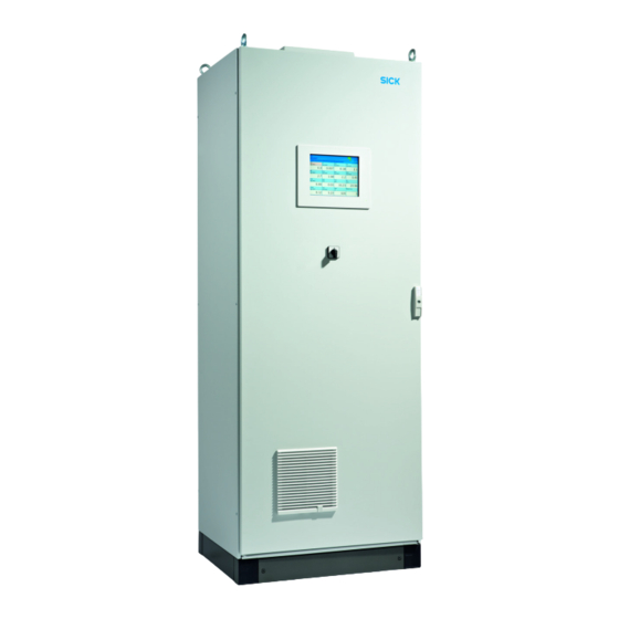
Exterior view 2.5.1 Fig. 2 Front view Operator panel: p. 32, §5.1 Equipment switch - Switching on: p. 29, §4.3 - Switching off: p. 84, §6.1 MCS100FT · Operating Instructions · 8011893 V 2-1 · © SICK AG... -
Page 16: Interior View
Oxygen measurement is performed with a zirconium dioxide (ZrO ) sensor (in short: O sensor). The O sensor is located within the cell enclosure. The signals of the O sensor are integrated in MCS100FT signal processing. MCS100FT · Operating Instructions · 8011893 V 2-1 · © SICK AG... -
Page 17: Toc With Fid-100Ft (Option)
Product Description TOC with FID-100FT (option) 2.5.5 As an option, the MCS100FT can be fitted with a FID (Flame Ionization Detector) to mea- sure the organically bound total carbon (TOC). The FID is located in the cell enclosure. The signals of the FID-100FTs are integrated in MCS100FT signal processing. -
Page 18: Gas Flow Plan
Backflush (5 - 7 bar) Sampling probe Span gas feed to probe (option) (option) Sample gas Sample gas (option) Cell Span gases (approx. 2 bar) FID fuel gas (option) (3±0.2 bar) MCS100FT · Operating Instructions · 8011893 V 2-1 · © SICK AG... -
Page 19: Preparations For Initial Start-Up
Preparations for Initial Start-up MCS100FT Preparations for Initial Start-up Installation Assembly MCS100FT · Operating Instructions · 8011893 V 2-1 · © SICK AG... -
Page 20: Scope Of Delivery
● Set up the MCS100FT in a low-vibration environment whenever possible. ● Set up the MCS100FT as close as possible to the sampling point. ● Short sample gas lines result in short lag times. Maximum length of sample gas line: 35 m. -
Page 21: Transport And Installation
The measured values could possibly be incorrect if the gas path is leaky. ● The gas lines to the MCS100FT may only be laid by skilled persons who, based on their training and knowledge as well as knowledge of the relevant regulations, can assess the tasks given and recognize the dangers involved. - Page 22 Sample gas outlet Screw fitting DN 8/10 Heated sample gas line inlet 1 Lay the sample gas line from the sampling probe to the MCS100FT. Observe the information concerning laying sample gas lines enclosed with the sample gas lines.
-
Page 23: Connecting The Gas Outlet
Lay the line so that it always runs downwards. Keep the line opening free from any blockages or liquids. Protect the line from frost. Connect the tube to the gas outlet. MCS100FT · Operating Instructions · 8011893 V 2-1 · © SICK AG... -
Page 24: Preparing The Electrical Installation
3. 5 WARNING: Health risk by voltage The preparation of the MCS100FT may only be performed by skilled electri- cians who, based on their technical training and knowledge as well as knowledge of the relevant regulations, can assess the tasks given and rec- ognize the hazards involved. -
Page 25: Ethernet Interface
– IP addresses and the addresses of the SCU and MCS100FT subnet masks: See SOPAS ET ( p. 14, §2.4.1). To change addresses: (Note: The unit (MCS100FT, FID-100FT or SCU) and the PC to be connected must be in the same network segment) a) Start SOPAS ET. -
Page 26: Connection To A Pc
Connect the Ethernet line. Modbus 3. 7 For information on Modbus parameter settings: “SCU” Operating Instruc- tions OPC (option) 3. 8 Let SICK Customer Service install the OPC software. MCS100FT · Operating Instructions · 8011893 V 2-1 · © SICK AG... -
Page 27: Start-Up
Start-up MCS100FT Start-up Switching on Assessment of error-free function MCS100FT · Operating Instructions · 8011893 V 2-1 · © SICK AG... -
Page 28: Persons Authorized To Carry Out The Start-Up
Persons authorized to carry out the start-up 4. 1 The MCS100FT may only be put into operation by skilled persons who, based on their device-specific training and knowledge of the device as well as knowl- edge of the relevant regulations, can assess the tasks given and recognize the dangers involved. -
Page 29: Switching On The Mcs100Ft
0.00 0.00 0.00 8 The MCS100FT is in Measuring mode when both status fields ( p. 33, §5.4.1) are green. Operation of the MCS100FT p. 31, §5 If the system does not switch to Measuring mode: Error message, see menu MCS100FT/Diagnosis/Logbook ( p. 62, §5.7.8.2). - Page 30 Start-up MCS100FT · Operating Instructions · 8011893 V 2-1 · © SICK AG...
-
Page 31: Operation
Operation MCS100FT Operation Operation Status messages MCS100FT · Operating Instructions · 8011893 V 2-1 · © SICK AG... -
Page 32: Operator Panel
Operation Operator panel 5. 1 The MCS100FT is operated via a touchscreen where you can perform inputs by touching the monitor. Operation via SOPAS ET (option) Operator menus and Measuring screens are also available on an exter- nal PC via Ethernet for user comfort (with the engineering tool SOPAS ET ... -
Page 33: Measuring Screen
The SCU has 2 status lines: First status line: SCU status line (higher level control unit). ● Second status line: Status line of the analyzer currently selected (MCS100FT or FID- ● 100FT) The status lines have status fields (depending on parameter settings) to display the respec- tive device status. - Page 34 The SCU status line parameter setting is normally “Group alarm”. This means that the error message of an analyzer not displayed is also shown as a status message in the SCU status line. MCS100FT · Operating Instructions · 8011893 V 2-1 · © SICK AG...
-
Page 35: Menu Trees - What Is Where
Some menus depend on the user level selected (password protected p. 51, §5.7.3). The menus for all user levels are shown completely in the following, however, to some extent, only those involved in operating the unprotected level are described. MCS100FT · Operating Instructions · 8011893 V 2-1 · © SICK AG... -
Page 36: Scu Menu Tree
p. 45, §5.6.9.1 Tests Manual Adjust p. 49, §5.6.9.3 Hardware Reset This menu is not used in the SCU. Please use the appropriate MCS100FT or FID-100FT menu. MCS100FT · Operating Instructions · 8011893 V 2-1 · © SICK AG... -
Page 37: Mcs100Ft Menu Tree
p. 66, §5.7.8.5 Energy values p. 67, §5.7.8.6 Sensor Values p. 69, §5.7.9 Maintenance p. 69, §5.7.9.1 Operation Mode Switch p. 69, §5.7.9.2 Status Reset MCS100FT · Operating Instructions · 8011893 V 2-1 · © SICK AG... -
Page 38: Fid-100Ft Menu Tree
p. 77, §5.8.7.3 Logbook p. 79, §5.8.8 Maintenance p. 79, §5.8.8.1 Ignition p. 79, §5.8.8.2 Operating mode p. 80, §5.8.8.3 Test gas switch MCS100FT · Operating Instructions · 8011893 V 2-1 · © SICK AG... -
Page 39: System Control Unit" (Scu) Menus
“SCU” Technical Information manual Parameter p. 45, §5.6.9 Maintenance Login (user levels) 5.6.3 Menu: System Control Unit/Login Equivalent to the menu for the MCS100FT: MCS100FT/Login p. 51, §5.7.3 Password Userlevel Designation Allowed actions Password None View measured values and parameters... -
Page 40: Start Screen
– Bargraph ( p. 42, §5.6.6.2) – LineWriter ( p. 42, §5.6.6.3) Setting Measuring Screen parameters ( “SCU Technical Information“ manual) ● Refresh interval for display: Approx. 1 second MCS100FT · Operating Instructions · 8011893 V 2-1 · © SICK AG... - Page 41 Activate 0 : 12345 Save 1 : 12340 (trailing zeros) Cancel 2 : 12300 Checkmark: Display line (Only effective for “LineWriter”) For bar graphs: Scale start and end. MCS100FT · Operating Instructions · 8011893 V 2-1 · © SICK AG...
- Page 42 1000.0 23.07.2010 p. 41 Date [dd.mm.yyyy] 500.0 500.0 Measured value graphic Time 14:23:40 14:53:40 14:38:40 [hh:mm:ss] Significance and settings: Measured value box ( p. 41, §5.6.6.1) MCS100FT · Operating Instructions · 8011893 V 2-1 · © SICK AG...
-
Page 43: Diagnosis
Logbook 5.6.7.1 Menu: System Control Unit/Diagnosis/Logbook This menu serves to make settings for the SCU logbook. The operation of the SCU logbook is equivalent to the operation of the MCS100FT logbook ( p. 62, §5.7.8.2). Logbook entries Logbook entry Description... - Page 44 Setting cyclic trigger parameters: “SCU Technical Information“ manual. Measure MCS100FT /System Control Unit/Diagnosis/Cyclic Trigger CT 1 NULL CT 2 NULL etc. NULL Designation Remark Cyclic trigger name MCS100FT · Operating Instructions · 8011893 V 2-1 · © SICK AG...
-
Page 45: Parameter Setting
p. 47 Digital Output p. 48 Analog Input p. 49 Analog Output Interface menu explanation: “SCU Technical Information“ manual The “Save” button has no significance. MCS100FT · Operating Instructions · 8011893 V 2-1 · © SICK AG... - Page 46 “SCU Technical Information“ manual). Shown automatically. DI(n)I [State] Computed value of [Source] (“Inverted” is taken into consideration) . DI(n) [Source] LED off: Physical contact open. LED on: Physical contact closed. MCS100FT · Operating Instructions · 8011893 V 2-1 · © SICK AG...
- Page 47 LED off: Relay open. LED on: Relay closed. DO(n) [Source] LED off: Program specification: Physical contact should be open. LED on: Program specification: Physical contact should be closed. MCS100FT · Operating Instructions · 8011893 V 2-1 · © SICK AG...
- Page 48 Number of the selected input. Shown automatically. Module Topographic addressing ( “SCU Technical Information“ manual). Shown automatically. AI(n)I [mA] Current measured on the analog input. AI(n) [phys. Unit] Converted physical measured value. MCS100FT · Operating Instructions · 8011893 V 2-1 · © SICK AG...
- Page 49 Please use the appropriate MCS100FT or FID-100FT menu. Hardware reset 5.6.9.3 Menu: System Control Unit/Maintenance/Hardware Reset Triggers an SCU restart and therefore the MCS100FT as well. Measure MCS100FT /System Control Unit/Maintenance/Hardware Reset Hardware Reset MCS100FT · Operating Instructions · 8011893 V 2-1 · © SICK AG...
-
Page 50: Mcs100Ft Menus
Upload all Parameters from Device p. 52, §5.7.5 Measured Values p. 52, §5.7.6 Parameters p. 55, §5.7.7 Adjustment p. 61, §5.7.8 Diagnosis p. 69, §5.7.9 Maintenance MCS100FT · Operating Instructions · 8011893 V 2-1 · © SICK AG... -
Page 51: Login (User Levels)
No further prompts are displayed, the parameters are loaded when the menu item is touched. If it is possible that parameters were changed on the MCS100FT resp. FID- 100FT via the Ethernet (e.g. via SOPAS ET): Perform “Upload all Parameters from Device” before changing parameters. -
Page 52: Measured Values
Pressure Control p. 54, §5.7.6.4 Logbook If it is possible that parameters were changed on the MCS100FT via the Ether- net (e.g. via SOPAS ET): Perform “Upload all Parameters from Device” ( p. 51, §5.7.4) before changing parameters. -
Page 53: Device Parameters
An input screen is shown after touching a field. Designation Remark IRC Operator Freely selectable IRC Sample Name Freely selectable IRC Sample Form Freely selectable IRC: IR Cube MCS100FT · Operating Instructions · 8011893 V 2-1 · © SICK AG... -
Page 54: Temperature Control
750 hPa Logbook 5.7.6.4 Menu: MCS100FT/Parameters/Logbook This menu serves to enter the settings for the logbook ( p. 62, §5.7.8.2) of the MCS100FT analyzer. (The SCU has an own setting for its own logbook p. 43, §5.6.7.1) Measure MCS100FT... -
Page 55: Adjustment
Designation Remark O2 Sensor Driftcheck Drift check of O sensor. Presetting p. 58, §5.7.7.3. O2 Sensor Adjustment Adjustment check of O sensor. Presetting p. 58, §5.7.7.3. MCS100FT · Operating Instructions · 8011893 V 2-1 · © SICK AG... - Page 56 Name of component. Active Checkmark: Component is active. “Operating state” Display of current operating state of the MCS100FT. “1234 s” State active since [s]. “1234 s” Remaining time [s]. Optional MCS100FT · Operating Instructions · 8011893 V 2-1 · © SICK AG...
-
Page 57: Adjustment Manual Ir Components
Set the factor of the reference point. Execute this command only when you are sure that you wish to change the factor. To terminate adjustment: Touch “Cancel” or go to “Measure”. MCS100FT · Operating Instructions · 8011893 V 2-1 · © SICK AG... -
Page 58: Parameters
Both span gases are used for adjustment. First Span Gas 2, then Span Gas 1. Adjust when Zeroadjust Checkmark: Automatically adjusts during zero point adjustment also with span gas 1. MCS100FT · Operating Instructions · 8011893 V 2-1 · © SICK AG... - Page 59 Criterion for stability of gas during gas feeding: Change Difference of H O absorbance. If, during leveling out, the value is below this “difference” between two measurements, the gas has “leveled out”. MCS100FT · Operating Instructions · 8011893 V 2-1 · © SICK AG...
- Page 60 Minimum purge time for sample gas before adjustment starts [seconds]. Span Factor internal Adjustment factor for adjustment with internal adjustment standard (filter wheel). Span Factor Adjustment factor for adjustment with span gas. MCS100FT · Operating Instructions · 8011893 V 2-1 · © SICK AG...
-
Page 61: Diagnosis
Remark Serial No. Serial number. Preset. Location Name The name entered here is shown in the menus to identify the MCS100FT (Example: “MCS100FT stack1”). IP configuration allowed Checkmark: The IP address can be changed via SOPAS ET. MCS100FT Firmware Ver- Firmware version of the MCS100FT. - Page 62 Operation Logbook of the MCS100FT and FID-100FT 5.7.8.2 Menus: MCS100FT/Diagnosis/Logbook and FID-100FT/Diagnosis/Logbook The internal status messages are recorded in the MCS100FT resp. FID-100FT logbook (separate logbooks) (format: Uncompressed data storage (SCU logbook p. 43, §5.6.7.1). Measure MCS100FT /MCS100FT/Diagnosis/Logbook Entries 65...
- Page 63 LEDs at the bottom of the interferometer must light. Check firm seating of the Ethernet con- nection between the electronics and inter- ferometer. The Ethernet LEDs at the elec- tronics unit must light/flash. MCS100FT · Operating Instructions · 8011893 V 2-1 · © SICK AG...
- Page 64 “M” classification in logbook, status field on operator panel ( p. 33, §5.4) lights yellow Logbook memory full Logbook is full Delete entries in the logbook ( p. 62, §5.7.8.2). MCS100FT · Operating Instructions · 8011893 V 2-1 · © SICK AG...
-
Page 65: Logbook
- Check sample gas feed for correct state (cleanness, pressure, temperature). - Feed zero gas and check display. - Feed span gas and check display. If fault persists: Contact SICK Customer Service. MCS100FT · Operating Instructions · 8011893 V 2-1 · © SICK AG... -
Page 66: Driftcheck (Qal3) With Span Gas
The menu is equivalent to menu Drift check (QAL3) with span gas (see above). Energy values 5.7.8.5 Menu: MCS100FT/Diagnosis/Energy values This menu serves to display 3 energies of the wavelength ranges. MCS100FT · Operating Instructions · 8011893 V 2-1 · © SICK AG... -
Page 67: Sensor Values
This menu serves exclusively for service purposes. Measure MCS100FT /MCS100FT/Diagnosis/Sensor Values Flow, Temperatures, Pressures O2 Sensor Power Supply Spectral Evaluation Spectrum Acquisition p. 68 (only in SOPAS ET) Spectra MCS100FT · Operating Instructions · 8011893 V 2-1 · © SICK AG... - Page 68 Time Time interval of continuous display. Save Save spectrum. Refresh Refresh spectrum. Connect measured points Connect measured points (line display) Show individual measured points Show individual measured points. MCS100FT · Operating Instructions · 8011893 V 2-1 · © SICK AG...
-
Page 69: Maintenance
p. 69, §5.7.9.1 Operation Mode Switch p. 69, §5.7.9.2 Status Reset Operation Mode Switch 5.7.9.1 Menu: MCS100FT/Maintenance/Operation Mode Switch This menu serves to switch the MCS100FT to the desired operating state. Measure MCS100FT /MCS100FT/Maintenance/Operation Mode Switch Measuring Maintenance Purge... -
Page 70: Fid-100Ft Menus (Option)
Failure ... when LED on: Measuring MCS100FT is in operating state “Measuring” Maintenance request MCS100FT is in operating state “Maintenance request“ Failure MCS100FT is in operating state ”Failure“ MCS100FT · Operating Instructions · 8011893 V 2-1 · © SICK AG... -
Page 71: Language
Measured value display 5.8.5.1 Menu: FID-100FT/Parameter/Measured value display This menu serves to set parameters for the measured value display (number of decimal places). Measure FID-100FT /FID-100FT/Parameter/Measured value display Decimal places MCS100FT · Operating Instructions · 8011893 V 2-1 · © SICK AG... -
Page 72: Span Gas Setting
Sample gas name 5.8.5.4 Menu: FID-100FT/Parameter/Sample gas name This menu serves to enter the sample gas name (freely selectable). Measure FID-100FT /FID-100FT/Parameter/Sample gas name Sample gas name CnHm MCS100FT · Operating Instructions · 8011893 V 2-1 · © SICK AG... -
Page 73: Device Parameters
Averaging time [s] for span gas during span gas adjustment. Purge time Purge time [s] with zero gas after adjustment completion until the measured value is released again. MCS100FT · Operating Instructions · 8011893 V 2-1 · © SICK AG... -
Page 74: Adjustment
LED on: Adjustment blocked by MCS100FT internal sequences. Wait until the LED goes off. Zero and Responsivity Start: Select “Start” Zero Terminate: Select “Stop” Responsivity Process Current device state Execute Execute selection MCS100FT · Operating Instructions · 8011893 V 2-1 · © SICK AG... -
Page 75: Diagnosis
Serial number xxxx Operation hours counter xxxh Location Location 1 Firmware: Name xxxx Firmware: ID xxxx Firmware: Version xxxx Firmware: Date xxxx Significance of LEDs p. 70, §5.8.3 MCS100FT · Operating Instructions · 8011893 V 2-1 · © SICK AG... -
Page 76: Adjustment Results
Span gas concentration set. (only shown for sensitivity drift) Span gas name Span gas name. (only shown for sensitivity drift) Measurement range Full scale value Measuring unit Sample gas unit. MCS100FT · Operating Instructions · 8011893 V 2-1 · © SICK AG... - Page 77 “M” classification in logbook, status field on operator panel ( p. 33, §5.4) lights yellow Operation Mode Switch p. 79, service-mode-is-ON Maintenance mode activated manually. §5.8.8.2 realtime-clock-not-set Date and time not set. Set date and time p. 73, §5.8.5.5 MCS100FT · Operating Instructions · 8011893 V 2-1 · © SICK AG...
- Page 78 Error in Logbook manage- errorer ment. The device can still be used but must be checked Contact SICK Customer Ser- Warning-logging-file-write-err vice. Warning-logbook-error If fault persists: Contact SICK Customer Service. MCS100FT · Operating Instructions · 8011893 V 2-1 · © SICK AG...
-
Page 79: Maintenance
Service mode leaving Delay time until the FID-100FT switched automatically to Measuring mode. lock-in Maintenance mode cannot be exited. Please contact SICK Customer Service. Maintenance mode Select Maintenance mode MCS100FT · Operating Instructions · 8011893 V 2-1 · © SICK AG... - Page 80 Button serves to switch span gas on. LED “Span gas” then goes on. Turn test gas off Button serves to switch zero resp. span gas off again. LED “Test gas off” then goes on. MCS100FT · Operating Instructions · 8011893 V 2-1 · © SICK AG...
-
Page 81: Starting Important Operating Sequences
Menu: FID-100FT/Adjustment/Zero point ( p. 74, §5.8.6) Menu: FID-100FT/Maintenance/Test gas switch ( p. 80, §5.8.8.3) Checking without test gas (option) 5.9.3 MCS100FT: ● Menu: MCS100FT/Adjustment ( p. 55, §5.7.7) MCS100FT · Operating Instructions · 8011893 V 2-1 · © SICK AG... - Page 82 Operation MCS100FT · Operating Instructions · 8011893 V 2-1 · © SICK AG...
-
Page 83: Shutdown
Shutdown MCS100FT Shutdown Switching off the MCS100FT Shutting down the MCS100FT Transport Disposal MCS100FT · Operating Instructions · 8011893 V 2-1 · © SICK AG... -
Page 84: Switching Off (For A Period Up To Approx. 2 Weeks)
Shutting down 6. 2 Switch the MCS100FT off ( p. 84, §6.1). The shutdown of the MCS100FT may be performed by trained personnel only. ● Moisture in the interferometer causes damage. Check the drying agent cartridge monthly even after shutting down ( p. 90, §7.2.3). -
Page 85: Disposal
The following subassemblies could contain substances that have to be disposed of sepa- rately: Electronics: Capacitors, rechargeable batteries, batteries. ● Display: Liquid of LC display. ● Sample gas filters: Sample gas filters could be contaminated by pollutants. ● MCS100FT · Operating Instructions · 8011893 V 2-1 · © SICK AG... - Page 86 Shutdown MCS100FT · Operating Instructions · 8011893 V 2-1 · © SICK AG...
-
Page 87: Scheduled Maintenance
Scheduled Maintenance MCS100FT Scheduled Maintenance Maintenance plan Spare parts MCS100FT · Operating Instructions · 8011893 V 2-1 · © SICK AG... -
Page 88: Maintenance Intervals
Filter pad for air outlet On request Drying agent cartridge, interferometer 5320799 As required Only for the “IP54” version as required Recommendation: In case moisture has penetrated the interferometer. MCS100FT · Operating Instructions · 8011893 V 2-1 · © SICK AG... -
Page 89: Description Of Maintenance Work
Filter pad air outlet (for version “IP54”) 5309684 The MCS100FT does not have to be switched off. 1 Remove the fan grill. 2 Insert a new fan pad immediately. 3 Refit the fan grill. MCS100FT · Operating Instructions · 8011893 V 2-1 · © SICK AG... -
Page 90: Checking/Replacing The Drying Agent Cartridge In The Interferometer
Moisture in the interferometer causes damage. When one indicator field is light red: Check cause (e.g. condition of the instrument air supply). Replace drying agent cartridge ( p. 91, §7.2.3.1). MCS100FT · Operating Instructions · 8011893 V 2-1 · © SICK AG... - Page 91 3 Immediately insert new drying agent cartridge. 4 Reinstall the cover (curves “at the rear”) and screw tight. Recommendation: Keep a new drying agent cartridge in storage. MCS100FT · Operating Instructions · 8011893 V 2-1 · © SICK AG...
- Page 92 Scheduled Maintenance MCS100FT · Operating Instructions · 8011893 V 2-1 · © SICK AG...
-
Page 93: Clearing Malfunctions
Clearing Malfunctions MCS100FT Clearing Malfunctions Fuses Status messages Implausible measured values FID-100FT does not ignite MCS100FT · Operating Instructions · 8011893 V 2-1 · © SICK AG... -
Page 94: Fuses
Interferometer/ Cooling unit Cabinet light cabinet fan (option) It is possible that the fuses of your MCS100FT have a different assignment. Refer to the delivered System Documentation for fuse assignment. Faults on the monitor 8. 2 Error Possible cause Remarks Monitor is blank. -
Page 95: Indicators On The Operator Panel
( p. 62, §5.7.8.2). Correct the malfunction or have it corrected by trained personnel. If it was possible to correct the malfunction without switching the MCS100FT off (e.g. clearing a jam when the “sample gas flow” malfunction occurred), the MCS100FT auto- matically switches back to Measuring mode. -
Page 96: Malfunctions Of The I/O Modules
● If not: Is the fuse in the MCS100FT switched on? ( p. 94, §8.1) Is the mains switch on the bottom of the interferometer switched on? Check firm seating of the power plug on the bottom of the interferometer. -
Page 97: Technical Documentation
Technical Documentation MCS100FT Technical Documentation Dimensions Technical data MCS100FT · Operating Instructions · 8011893 V 2-1 · © SICK AG... -
Page 98: Approvals
Contamination: The device operates safely in an environment up to degree of contami- ● nation 2 according to EN 61010-1 (usual, nonconductive contamination and temporary conductivity by occasional moisture condensation). MCS100FT · Operating Instructions · 8011893 V 2-1 · © SICK AG... -
Page 99: Dimensions
Technical Documentation Dimensions 9 . 2 806 (31.7) 610 (24) 535 (21) 735 (29) 29 (1.14) Air outlet with the “IP54” option 300 (11.8) Dimensions in mm (inch) MCS100FT · Operating Instructions · 8011893 V 2-1 · © SICK AG... -
Page 100: Technical Data
- Flow Approx. 300 l/h - Temperature, cell Max. 200°C (390°F) - Temperature, sampling point Max. 1300°C (2370°F) - Input pressure 90 ... 110 kPa (0.9 ... 1.1 bar) MCS100FT · Operating Instructions · 8011893 V 2-1 · © SICK AG... - Page 101 - Sample gas inlet DN 4/6 - Ejector induction air DN 6/8 - Test gas inlet DN 4/6 - FID-100FT fuel gas inlet DN 4/6 - Gas outlet DN 8/10 MCS100FT · Operating Instructions · 8011893 V2-1 · © SICK AG...
- Page 102 System-dependent configuration delivered system documentation. Description “Modular I/O System” Operating Instructions Emissions Generated condensate: Approx. 1 l/day (at approx. 25% by vol. H O in sample gas) MCS100FT · Operating Instructions · 8011893 V 2-1 · © SICK AG...
- Page 103 - Automatically ......55 - MCS100FT ....... 61 - FID-100FT .
- Page 104 Parameter - MCS100FT ....... 63 - FID-100FT ....... . 71 - SCU .
- Page 105 - FID-100FT ....... 51 - MCS100FT ....... 51 - SCU .
- Page 106 MCS100FT SICK worldwide You will find our local subsidiary or agency at: www.sick.com Your local sales and service partner SICK AG | Waldkirch | Germany | www.sick.com...
Need help?
Do you have a question about the MCS100FT and is the answer not in the manual?
Questions and answers