Sign In
Upload
Download
Table of Contents
Contents
Add to my manuals
Delete from my manuals
Share
URL of this page:
HTML Link:
Bookmark this page
Add
Manual will be automatically added to "My Manuals"
Print this page
×
Bookmark added
×
Added to my manuals
Manuals
Brands
WAGO Manuals
I/O Systems
753-461
Manual
WAGO 753-461 Manual
2ai pt 100/rtd 2-channel analog input for rtds
Hide thumbs
1
2
Table Of Contents
3
4
5
6
7
8
9
10
11
12
13
14
15
16
17
18
19
20
21
22
23
24
25
26
27
28
29
30
31
32
33
34
35
36
37
38
39
40
41
42
43
44
45
46
47
48
49
50
51
52
53
54
55
56
page
of
56
Go
/
56
Contents
Table of Contents
Bookmarks
Table of Contents
Table of Contents
Notes about this Documentation
Validity of this Documentation
Copyright
Table 1: Variants
Symbols
Number Notation
Font Conventions
Table 2: Number Notation
Table 3: Font Conventions
Important Notes
Legal Bases
Subject to Changes
Personnel Qualifications
Use of the 750 Series in Compliance with Underlying Provisions
Technical Condition of Specified Devices
Disposal
2.1.4.1.1 Electrical and Electronic Equipment
2.1.4.1.2 Packaging
Safety Advice (Precautions)
Device Description
View
Figure 1: View
Table 4: Legend for Figure "View
Connectors
Data Contacts/Local Bus
Figure 2: Data Contacts
Power Jumper Contacts/Field Supply
Cage Clamp
Figure 3: CAGE CLAMP ® Connectors
Table 5: Legend for Figure "CAGE CLAMP ® Connectors
Display Elements
Figure 4: Display Elements
Table 6: Legend for Figure "Display Elements
Operating Elements
Schematic Diagram
Figure 5: Schematic Diagram
Technical Data
Device Data
Power Supply
Communication
Inputs
Table 7: Technical Data - Device
Table 8: Technical Data - Power Supply
Table 9: Technical Data - Communication
Table 10: Technical Data - Inputs (RTD Model 753-461)
Climatic Environmental Conditions
Connection
Table 11: Technical Data - Climatic Environmental Conditions
Table 12: Technical Data - Field Wiring
Table 13: Technical Data - Data Contacts
Approvals
Standards and Guidelines
Process Image
I/O Module with Pt Resistance Sensors
Pt100
Table 14: I/O Modules with Pt Resistance Sensors
Table 15: Process Image, Pt100, with Wire Break Diagnostics
753-461/003-000 Configurable I/O Module
Table 16: Configurable I/O Module
Table 17: Setting Options for the 753-461/003-000 I/O Module
Table 18: 753-461/003-000 I/O Module, Offset and Gain Values
Table 19: 753-461/003-000 I/O Module, Hardware Matching Input Fields
Mounting
Mounting Sequence
Inserting and Removing Devices
Inserting the I/O Module
Figure 6: Insert I/O Module (Example)
Figure 7: Snap the I/O Module into Place (Example)
Removing the I/O Module
Figure 8: Removing the I/O Module (Example)
I/O Modules with Pluggable Wiring Level (Series 753)
Figure 9: Plug and I/O Module
Figure 10: Assignment of I/O Module to Plug Using Mini-WSB Tags
Coding
Figure 11: Attachment of Cable Binders
Figure 12: Assembling the Coding Fingers
Figure 13: Inserting the Coding Fingers
Figure 14: Plugging the Plug into Place
Figure 15: "Sure Match" Coding Fingers
Plug Removal
Figure 16: Pulling the Pull Tab
Figure 17: Removing the Plug Without Tools
Figure 18: Removing the Plug Using a Screwdriver
Connect Devices
Connecting a Conductor to the CAGE CLAMP
Figure 19: Connecting a Conductor to a CAGE CLAMP
Connection Examples
RTD, 2-Wire Connection
Figure 20: Connection Example: 2 × RTD, 2-Wire Connection
RTD, 3-Wire Connection
Figure 21: Connection Example: 2 × RTD, 3-Wire Connection
Use in Hazardous Environments
Marking Configuration Examples
Marking for Europe According to ATEX and Iecex
Figure 22: Marking Example According to ATEX and Iecex
Figure 23: Text Detail - Marking Example According to ATEX and Iecex
Table 20: Description of Marking Example According to ATEX and Iecex
Figure 24: Marking Example for Approved Ex I I/O Module According to
Figure 25: Text Detail - Marking Example for Approved Ex I I/O Module According to ATEX and Iecex
Table 21: Description of Marking Example for Approved Ex I I/O Module According to ATEX and Iecex
Table 23: Description of Marking Example for Approved Ex I I/O Module
Marking for the United States of America (NEC) and Canada (CEC)
Figure 26: Marking Example According to NEC
Figure 27: Text Detail - Marking Example According to NEC 500
Table 22: Description of Marking Example According to NEC 500
Figure 28: Text Detail - Marking Example for Approved Ex I I/O Module
Figure 29: Text Detail - Marking Example for Approved Ex I I/O Module
Table 24: Description of Marking Example for Approved Ex I I/O Modules
Figure 30: Text Detail - Marking Example for Approved Ex I I/O Modules
Table 25: Description of Marking Example for Approved Ex I I/O Modules
Installation Regulations
Special Notes Regarding Explosion Protection
Special Notes Regarding ANSI/ISA Ex
List of Figures
List of Tables
Advertisement
Quick Links
Download this manual
Manual
WAGO-I/O-SYSTEM 750
753-461(/xxx-xxx)
2AI Pt 100/RTD
2-Channel Analog Input for RTDs
Version 1.3.1
Table of
Contents
Previous
Page
Next
Page
1
2
3
4
5
Advertisement
Table of Contents
Need help?
Do you have a question about the 753-461 and is the answer not in the manual?
Ask a question
Questions and answers
Related Manuals for WAGO 753-461
I/O Systems WAGO 750 Series Manual
(76 pages)
I/O Systems WAGO 753-454 Manual
2ai 4-20ma diff. 2-channel analog input module 4-20 ma differential inputs (50 pages)
I/O Systems WAGO I/O-SYSTEM 753-456 Manual
2 ai ±10 v dc, differential inputs 2-channel analog input module ±10 v (50 pages)
I/O Systems WAGO WAGO-I/O-SYSTEM 750 Series Manual
4fdi 24v profisafe v2 ipar safety 4-channel digital input module profisafe v2 (138 pages)
I/O Systems WAGO I/O SYSTEM 750 Series Manual
2 ai ±10 v dc, differential inputs 2-channel analog input module ±10 v (50 pages)
I/O Systems WAGO 750 Series Manual
Knx/eib/tp1 module router mode (44 pages)
I/O Systems WAGO Automation WAGO-I/O-SYSTEM 750 Manual
Knx/eib/tp1 module (20 pages)
I/O Systems WAGO 750 Series System Manual
(56 pages)
I/O Systems WAGO 750 Series Manual
(66 pages)
I/O Systems WAGO 750 Product Manual
Smi-master lovo; dc 24 v (44 pages)
I/O Systems WAGO 750 Product Manual
(92 pages)
WAGO 750, 753 Manual
(article)
I/O Systems WAGO WAGO-I/O-SYSTEM 750 Manual
2ai pt 100/rtd 2-channel analog input for rtds (56 pages)
I/O Systems WAGO I/O System 750 Manual
2do 24v dc 0.5a/ diagnostics 2-channel digital output; 24 v dc; short-circuit protected; high-side switching; with diagnostics (52 pages)
I/O Systems WAGO 753-482 Manual
2ai 4-20ma 12 bit s.e. hart 2-channel analog input; 4-20 ma; hart; single-ended (s.e.) for wago i/o system 750 (102 pages)
I/O Systems WAGO 750 Manual
4fdi 24v profisafe (132 pages)
Summarization of Contents
Notes about this Documentation
Validity and Copyright
Details documentation applicability and copyright restrictions.
Important Notes
Legal, Personnel, and Usage Guidelines
Covers legal aspects, personnel qualifications, and device usage compliance.
Device Condition, Disposal, and Safety
Explains device state, disposal, and safety aspects like electrical disposal.
Safety Advice and Precautions
Critical Safety Warnings and Procedures
Details critical safety warnings, installation requirements, and contact guidelines for safe operation.
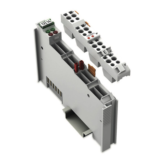
Device Description
Module Overview and Components
Describes the physical layout, connectors, and status indicators of the module.
Technical Specifications
Details electrical, environmental, and communication parameters of the module.
Regulatory Compliance
Covers module approvals, standards, and guidelines.
Process Image and Configuration
Pt100 Sensor Data Processing
Details Pt100 sensor input, temperature conversion, and data representation.
Configurable I/O Module Settings
Describes the configurable version and its settings via WAGO-I/O-CHECK.
Mounting and Wiring
Mounting Sequence and Procedures
Outlines steps for mounting, inserting, and removing modules on a carrier rail.
Pluggable Wiring and Coding
Explains pluggable wiring, coding for correct pairing, and plug removal.
Connecting Conductors
Explains how to terminate conductors using CAGE CLAMP® and provides connection examples.
Hazardous Environment Operation
Marking and Certification Examples
Details specific markings for ATEX, IECEx, NEC, and CEC certifications.
Installation Regulations and Safety
Lists critical installation rules, warnings, and precautions for explosive atmospheres.
Table of Contents
Print
Rename the bookmark
Delete bookmark?
Delete from my manuals?
Login
Sign In
OR
Sign in with Facebook
Sign in with Google
Upload manual
Upload from disk
Upload from URL
Need help?
Do you have a question about the 753-461 and is the answer not in the manual?
Questions and answers