Sign In
Upload
Download
Table of Contents
Contents
Add to my manuals
Delete from my manuals
Share
URL of this page:
HTML Link:
Bookmark this page
Add
Manual will be automatically added to "My Manuals"
Print this page
×
Bookmark added
×
Added to my manuals
Manuals
Brands
Aplisens Manuals
Transmitter
LI-24G Exi
User manual
Aplisens LI-24G Exi User Manual
Temperature transmitters
Hide thumbs
1
2
3
Table Of Contents
4
5
6
7
8
9
10
11
12
13
14
15
16
17
18
19
20
21
22
23
24
25
26
27
28
page
of
28
Go
/
28
Contents
Table of Contents
Bookmarks
Table of Contents
Table of Contents
1 Introduction
Purpose of the Document
Registered Trademarks
Definitions and Abbreviations
Table 1. Definitions and Abbreviations
Transmitter Set Range
Figure 1. Set Range and Measurement Limits
Figure 2. Warning Plate - Protective Seal
2 Safety
3 Transport and Storage
Delivery Check
Transport
Storage
4 Guarantee
Figure 3. Examples of LI-24G Transmitter Nameplates in Standard and Exi Version
Figure 4. Examples of LI-24L Transmitter Nameplates in Standard and Exi Version
5 Identification
CE Mark, Declaration of Conformity
Manufacturer's Address
Transmitter Identification
Figure 5. LI-24L Transmitter Installation on a DIN Rail
Installation of Head-Mounted Transmitter LI-24G in the Housing
6 Installation
General Recommendations
Installation of Rail-Mounted Transmitter LI-24L on a DIN Rail
Figure 6. Installation of the LI-24G Transmitter in an Example Enclosure Manufactured by Aplisens
Figure 7. Fastening Screw Lock Protection in the LI-24G Transmitter
Figure 8. Markings of LI-24L Transmitter Terminals
Figure 9. Markings of LI-24G Transmitter Terminals
7 Electrical Connection
Cable Connection to Transmitter Terminals
Cable Connection
Figure 10. Methods of Connecting Sensors, Potentiometers and Voltage Sources
Options for Connecting Sensors, Potentiometers and Voltage Sources to the Transmitter
Connection of Transmitters with the Option of Using Local HART Communication
Figure 12. Electrical Connection 4
Table 2. Permissible Transmitter Supply Voltages
Final Inspection of Cabling
Shielding, Equipotential Bonding
Figure 11. Electrical Connection 4
Transmitter Power Supply
Transmitter Supply Voltage
Specifications of Electrical Switching Terminals
Resistance Load in Power Supply Line
8 Operation
Operating Temperature
Remote Configuration of Setpoints (HART 5)
Compatible Devices
Compatible Configuration Software
Method of Connecting Communication Devices
Figure 13. Set Range Current, Saturation Currents, Alarm Currents in Standard Mode
9 Start-Up
Alarm Configuration
Figure 14. Set Range Current, Saturation Currents, Alarm Currents in NAMUR Mode
Configuration of the Operating Mode
Figure 15. LED Indicator on the LI-24L Transmitter
Table 3. Types of Measurements, Linearization and Mathematical Operations
10 Maintenance
Periodic Inspections
Non-Periodic Inspections
Spare Parts
Repair
Returns
11 Scrapping, Disposal
12 History of Revisions
Advertisement
Quick Links
1
Cable Connection to Transmitter Terminals
Download this manual
Revision 01.A.002
EN.IO.LI.24.L.G
NOVEMBER 2020
USER'S MANUAL
TEMPERATURE TRANSMITTERS
LI-24L
LI-24G
APLISENS S.A., 03-192 Warsaw, Morelowa 7 St,
tel. +48 22 814 07 77; fax +48 22 814 07 78
www.aplisens.com, e-mail:
export@aplisens.com
Table of
Contents
Previous
Page
Next
Page
1
2
3
4
5
Advertisement
Table of Contents
Need help?
Do you have a question about the LI-24G Exi and is the answer not in the manual?
Ask a question
Questions and answers
Related Manuals for Aplisens LI-24G Exi
Transmitter Aplisens LI-24 User Manual
Rail-mounted smart temperature transmitter (17 pages)
Transmitter Aplisens LI-24G User Manual
Temperature transmitters (27 pages)
Transmitter Aplisens LI-24L User Manual
Temperature transmitters (28 pages)
Transmitter Aplisens LI-24L Manual
Rail / head-mounted smart temperature transmitters (16 pages)
Transmitter Aplisens LI-24L Safety User Manual
Temperature transmitters (28 pages)
Transmitter Aplisens LI-24ALW Safety User Manual
Smart temperature transmitter (25 pages)
Transmitter Aplisens LI-24ALW User Manual
Temperature transmitter (24 pages)
Transmitter Aplisens LI-24ALW User Manual
Smart temperature transmitter (25 pages)
Transmitter Aplisens APC-2000ALW User Manual
Pressure transmitters (29 pages)
Transmitter Aplisens APC-2000ALW User Manual
Explosion-proof device smart pressure transmitters smart pressure differential transmitters smart level probes (21 pages)
Transmitter Aplisens APC-2000ALW User Manual
Smart pressure transmitter; smart differential pressure transmitter; smart level transmitter (64 pages)
Transmitter Aplisens APC-2000ALW User Manual
Pressure and differential pressure transmitters with diaphragm seals (35 pages)
Transmitter Aplisens APR-2000ALW User Manual
Pressure transmitters and control instruments (76 pages)
Transmitter Aplisens APC-2000ALW/L Manual
Smart pressure transmitters; smart level probes (21 pages)
Transmitter Aplisens APT-2000ALW User Manual
Temperature transmitter (26 pages)
Transmitter Aplisens PCE-28.SMART User Manual
Smart pressure and differerential pressure transmitters (23 pages)
Summarization of Contents
1. Introduction to Temperature Transmitters
1.1. Purpose of the Document
Explains the scope and content of the user manual for temperature transmitters.
1.2. Registered Trademarks
Lists registered trademarks related to the product and its software.
1.3. Definitions and Abbreviations
1.4. Transmitter Set Range
2. Safety Precautions
3. Transport and Storage Guidelines
3.1. Delivery Check Procedure
Procedures for verifying the condition and completeness of the delivered equipment.
3.2. Transport Recommendations
Guidelines for the safe transport of transmitters to prevent damage.
3.3. Storage Conditions
Specifies the correct conditions for storing the transmitters.
4. Product Guarantee Information
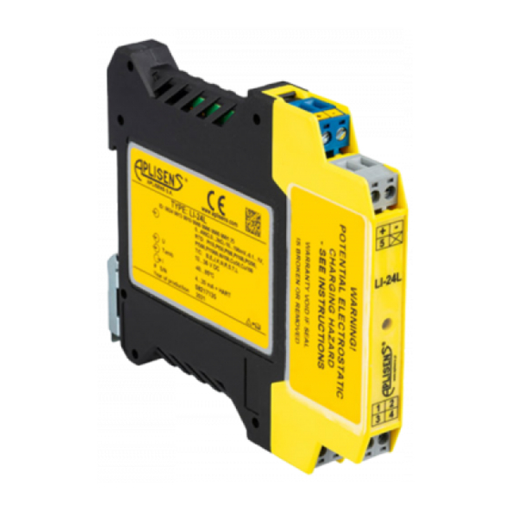
5. Transmitter Identification
5.1. Manufacturer's Address
Provides the official address of the manufacturer, Aplisens S.A.
5.2. Transmitter Nameplate Details
Details on nameplates, including type, serial number, and QR codes.
5.3. CE Mark and Conformity
Information regarding the device's compliance with safety standards and CE marking.
6. Installation Procedures
6.1. General Installation Recommendations
General advice for installing transmitters in suitable enclosures for protection.
6.1.1. Rail-Mounted LI-24L DIN Rail Installation
Step-by-step guide for mounting the LI-24L transmitter on a DIN rail.
6.1.2. Head-Mounted LI-24G Housing Installation
7. Electrical Connection
7.1. Cable Connection to Terminals
Details on connecting cables to the transmitter terminals for proper functionality.
7.1.2. Sensor, Potentiometer, Voltage Source Connections
7.2. Local HART Communication Setup
7.3. Transmitter Power Supply
7.3.1. Transmitter Supply Voltage Specifications
Specifies the permissible minimum and maximum supply voltages for the transmitter.
7.3.2. Electrical Switching Terminals Specs
Details on conductor cross-section area for electrical switching terminals.
7.3.3. Resistance Load in Power Supply Line
Discusses the impact of resistance load on the power supply line and provides a formula.
7.3.4. Shielding and Equipotential Bonding
7.4. Final Cabling Inspection
8. Operation and Configuration
8.1. Operating Temperature Limits
Lists the permissible operating temperature ranges for standard and Exi versions.
Remote HART Configuration
How to read and configure parameters using HART communication.
Compatible HART Communication Devices
Lists compatible hardware devices for HART communication.
Compatible HART Configuration Software
Lists compatible software for configuring the transmitter.
Connecting HART Communication Devices
Instructions for connecting devices for local HART communication.
9. Start-Up Procedures
9.1. Alarm Configuration
Configuring alarm thresholds and parameters for diagnostic alerts.
Transmitter Diagnostics Monitoring
LED Indicator Status Interpretation
9.2. Operating Mode Configuration
10. Maintenance Schedule
10.1. Periodic Inspections
Procedures for regular checks of terminal connections and mounting stability.
10.2. Non-Periodic Inspections
Inspection guidelines for devices exposed to damage or incorrect operation.
10.3. Spare Parts Availability
Information about replaceable parts, particularly for ATEX types.
10.4. Repair Process
Process for returning faulty or non-operational transmitters for repair.
10.5. Return Procedures
Cases where the transmitter should be returned to the manufacturer.
11. Scrapping and Disposal
12. History of Revisions
Table of Contents
Print
Rename the bookmark
Delete bookmark?
Delete from my manuals?
Login
Sign In
OR
Sign in with Facebook
Sign in with Google
Upload manual
Upload from disk
Upload from URL
Need help?
Do you have a question about the LI-24G Exi and is the answer not in the manual?
Questions and answers