Aplisens LI-24L Manual
Rail / head-mounted smart temperature transmitters
Hide thumbs
Also See for LI-24L:
- User manual (28 pages) ,
- User manual (28 pages) ,
- User manual (27 pages)
Table of Contents
Advertisement
Quick Links
EN.IX.LI.24.L.G
Revision 01.A.001
May 2020
EXPLOSION-PROOF DEVICE MANUAL
RAIL-MOUNTED SMART TEMPERATURE TRANSMITTERS
LI-24L, LI-24L SAFETY
HEAD-MOUNTED SMART TEMPERATURE TRANSMITTER
LI-24G, LI-24G SAFETY
APLISENS S.A., 03-192 Warsaw, Morelowa 7 St
tel. +48 22 814 07 77; fax +48 22 814 07 78
www.aplisens.com, e-mail:
export@aplisens.com
Advertisement
Table of Contents

Related Manuals for Aplisens LI-24L


Summary of Contents for Aplisens LI-24L
- Page 1 May 2020 EXPLOSION-PROOF DEVICE MANUAL RAIL-MOUNTED SMART TEMPERATURE TRANSMITTERS LI-24L, LI-24L SAFETY HEAD-MOUNTED SMART TEMPERATURE TRANSMITTER LI-24G, LI-24G SAFETY APLISENS S.A., 03-192 Warsaw, Morelowa 7 St tel. +48 22 814 07 77; fax +48 22 814 07 78 www.aplisens.com, e-mail: export@aplisens.com...
- Page 2 Explosion-proof installations should be made with special care and in accordance with standards and regulations applicable to this type of installations. Changes can be made in the manufacturing before the paper version of user documentation is updated. Up-to-date user manuals are available on the manufacturer's website: www.aplisens.com.
-
Page 3: Table Of Contents
8. INTRINSICALLY-SAFE Exi TRANSMITTERS LI24L AND LI-24L SAFETY 9 8.1. Standards used for assessment .................. 9 8.2. Transmitter intrinsic safety designations ..............9 8.3. Permissible input and output parameters of the intrinsic safety transmitters LI-24L and LI-24L Safety ...................... 10 9.1. Minimum and maximum supply voltage ..............10 9.2. - Page 4 EN.IX.LI.24.L.G Table 4. Permissible output parameters in the temperature sensor circuit (terminals "1", "2", "3", "4", "5") for the LI-24L and LI-24L Safety transmitters in Exi version ....... 10 Table 5. Transmitter supply voltages in Exi version ............... 10 Revision 01.A.001/2020.05...
-
Page 5: Introduction
EN.IX.LI.24.L.G INTRODUCTION This manual is only applicable to the LI-24L, LI-24L Safety, LI-24G i LI-24G Safety series transmitters in Exi (intrinsically safe). The transmitters are identified with model ID on nameplates and also as specified in section 3. Ex information are included in the “Product Certificate”. -
Page 6: Identification Marks
14. Identification of the explosion-proof version type, certificate identification see point 7.2 for LI-24G, LI-24G Safety and point 8.2 for LI-24L, LI-24L Safety; 15. Intrinsic safety parameters, i.e.: Ui, Ii, Pi, Li, Ci, Uo, Io, Po, Co, Lo. Figure 1. Sample transmitter nameplates LI-24G... -
Page 7: Construction Of The Transmitter
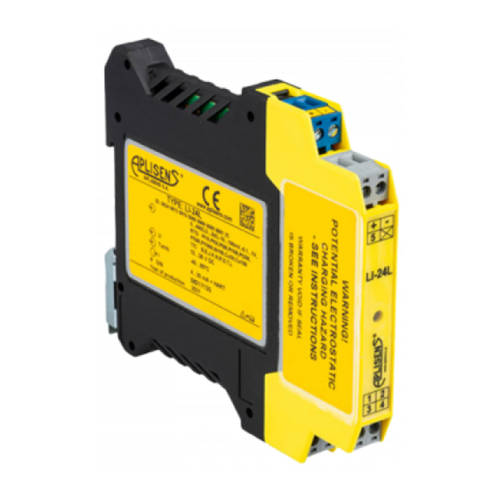
Figure 2. Sample transmitter nameplate LI-24L Safety CONSTRUCTION OF THE TRANSMITTER The LI-24L, LI-24L Safety, LI-24G, LI-24G Safety, temperature transmitter consist of a plastic housing and an electronic unit located inside that converts the signal from the measurement sensor to a unified output signal. LI-24L, LI-24L Safety, temperature transmitters are designed for direct mounting on DIN 35 rail. -
Page 8: Special Conditions Of Use
EN.IX.LI.24.L.G SPECIAL CONDITIONS OF USE The maximum temperature of the external heating source cannot heat the transmitter above the maximum ambient temperature declared by manufacturer. Temperature transmitters in potentially explosive areas should be installed in enclosures designed for operation in these areas and provide a minimum degree of protection: IP54 for Group I devices, IP20 for Group II devices and IP5X for Group III devices. -
Page 9: Permissible Input And Output Parameters Of The Intrinsic Safety Transmitters Li-24G And Li-24G Safety
The following ATEX and IECEx markings apply only to intrinsically safe transmitters marked with the type and model ID: LI-24L ID 0024 0009 ..., LI-24L Safety ID 0003 0005 0003 ..., ATEX: I M1 Ex ia I Ma II 1G Ex ia IIC T4/T5 Ga... -
Page 10: Permissible Input And Output Parameters Of The Intrinsic Safety Transmitters Li-24L And Li-24L Safety
-40⁰C≤Ta≤+85⁰C (T4) -40⁰C≤Ta≤+85⁰C (T4) -40⁰C≤Ta≤+85⁰C (T4) Table 4. Permissible output parameters in the temperature sensor circuit (terminals "1", "2", "3", "4", "5") for the LI-24L and LI-24L Safety transmitters in Exi version 3.3 mA 19.8 mW 2.5 µF 2 mH TRANSMITTER POWER SUPPLY PARAMETERS 9.1. -
Page 11: Linear Power Supply Example
EN.IX.LI.24.L.G EXAMPLE OF POWER SUPPLY FOR TRANSMITTERS IN EXPLOSION HAZARD AREAS. 10.1. Linear power supply example For example, linear power supply is provided by a typical barrier with the following parameters Uo = 28V; Io = 0.1A; Po = 0.7W; Rw = 280. Figure 3. -
Page 12: Connecting Exi Transmitters
EN.IX.LI.24.L.G Rectangular power supply means that the voltage of an intrinsically safe power adapter does not change until the current limiter is activated. The level of protection of rectangular power supply adapters is usually “ib”. A transmitter supplied from such power adapter is usually an “ib” intrinsically safe device. An example of power supply in practice: A stabilized power adapter with Uo = 24 V, “ib”... -
Page 13: Additional Information
EN.IX.LI.24.L.G The electrical system for connecting transmitters should meet installation requirements of applicable standards. No repairs or alterations to the transmitter electrical system are permitted. Only the manufacturer or a facility authorized by the manufacturer may assess damages and repair the device (if possible). To minimize the risk of electrostatic discharge in potentially explosive areas, make connections to the transmitter terminals outside these areas.
Need help?
Do you have a question about the LI-24L and is the answer not in the manual?
Questions and answers