Table of Contents
Advertisement
Quick Links
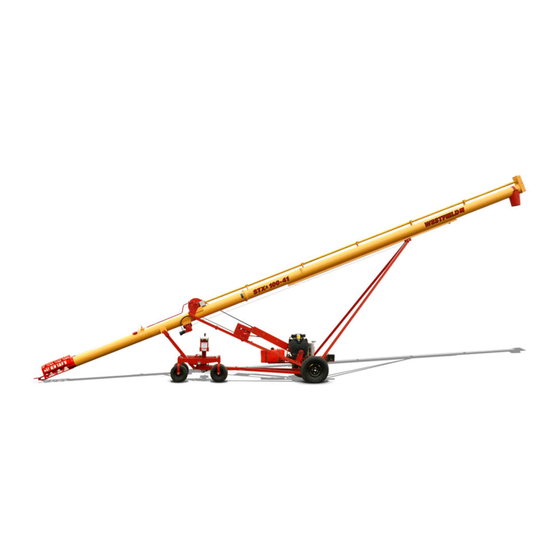
HD Self-Propelled Auger Kit
Assembly Manual
This manual applies to:
Westfield STX2, Hutchinson STX2, Mayrath STX2, and AGI XTA:
36', 41', 46', 51'
Read this manual before using product. Failure to
follow instructions and safety precautions can
result in serious injury, death, or property
damage. Keep manual for future reference.
LOOKING FOR PARTS?
Check out our online
Parts Catalog!
Part Number: 31121 R0
Revised: August 2020
Original Instructions
Advertisement
Table of Contents

Summarization of Contents
1. Introduction
1.1. Serial Number Location
Location of the serial number for the self-propelled auger kit.
2. Safety
2.1. Safety Alert Symbol and Signal Words
Explains safety alert symbols and signal words (Danger, Warning, Caution, Notice) used in the manual.
2.2. General Safety
Provides general safety instructions for assembly and operation, emphasizing qualified personnel and manufacturer guidelines.
2.3. Rotating Parts Safety
Safety precautions related to rotating parts like pulleys, belts, chains, and sprockets.
2.4. Hydraulic Winch Safety
Safety guidelines for operating and maintaining the hydraulic winch.
2.5. Drives and Lockout Safety
Safety procedures for power sources, including lockout and shutdown during maintenance.
2.5.1 Gas Engine Safety
Safety precautions for the gas engine, including fueling, ventilation, and lockout procedures.
2.5.2 Hydraulic Power Safety
Safety measures for hydraulic systems, including fluid pressure, line handling, and leak detection.
2.6. Tire Safety
Safety procedures for mounting, maintaining, and inflating tires.
2.7. Personal Protective Equipment
Lists essential Personal Protective Equipment (PPE) such as safety glasses, work gloves, and steel-toe boots.
2.8. Safety Equipment
Recommends keeping essential safety equipment like fire extinguishers and first-aid kits on site.
2.9. Safety Decals
Guidelines for maintaining, replacing, and understanding safety decals.
2.9.1 Decal Installation/Replacement
Step-by-step instructions for properly installing or replacing safety decals.
2.9.2 Safety Decal Locations and Details
Refers to figures showing the locations and messages of safety decals on the equipment.
3. Assembly
3.1. Assembly Safety
Safety precautions specific to the assembly process, emphasizing teamwork and proper tools.
3.2. Check Shipment
Instructions for verifying received parts against the packing slip and reporting any damage or missing items.
3.3. Before You Begin
Steps to take before starting assembly, including familiarizing with parts and organizing hardware.
3.4. Hydraulic Fittings and Bolt Tightening
Guidelines for tightening hydraulic fittings and bolts, emphasizing manufacturer specifications and avoiding over-tightening.
3.5. Install the Hydraulic Pump
Instructions for installing the hydraulic pump assembly using specified hardware.
3.6. Install the Hydraulic Oil Tank
Steps for mounting the hydraulic oil tank, including placement of mounts relative to the tube end.
3.7. Install the Hydraulic Filter
Instructions for installing the hydraulic filter head and filter, ensuring correct hose orientation for oil flow.
3.8. Install the Hydraulic Manifold
Steps for installing the hydraulic manifold using bolts and lock washers.
3.9. Install the Over-Center Drive
Procedure for installing the over-center drive assembly onto the axle tube.
3.10. Adjust the Pinion Gear
Guidance on adjusting the pinion gear for proper meshing with the ring gear to prevent damage.
3.11. Install the Hydraulic Winch
Instructions for mounting the hydraulic winch assembly using washers and locknuts.
3.12. Connect the Lift Cable
Steps for connecting the lift cable to the winch drum, ensuring at least three wraps.
3.13. Install the Undercarriage
Instructions for installing the main undercarriage components.
Connecting the SP Reach Arms to the Mover Assembly
Connects the SP Reach Arms to the mover assembly.
Connecting the SP Reach Arms to the Axle
Connects the SP Reach Arms to the unit's axle.
Installing the SP Reach Arm Tie Braces
Instructions for installing SP reach arm tie braces, noting it's not for the 36' model.
Installing the Slider Assembly onto the Tube and Mover Assembly
Attaches the slider assembly to the tube and mover assembly.
Installing the Controls Tower
Instructions for installing the controls tower, specifying its position from the arm tube.
Installing the Mover Controls Assembly
Steps for attaching the mover controls assembly to the controls tower.
Installing the Line Blocks (36' Model)
Instructions for installing line blocks on the 36' model, with a note to hand-tighten.
Installing the Bent Steel Hydraulic Lines (41'/46'/51' Models)
Steps for installing bent steel hydraulic lines on specific models.
Installing the Straight Hydraulic Steel Lines onto the Axle
Instructions for installing straight hydraulic steel lines onto the axle.
3.14. Install the Hydraulic Adapters
Instructions for installing hydraulic adapters at various connection points.
Installing Adapters at the Valve
Steps for installing hydraulic adapters at the hydraulic valve.
Installing Adapters at the Hydraulic Motors
Steps for installing hydraulic adapters onto the hydraulic motors.
Installing Adapters at the Hydraulic Winch
Instructions for installing hydraulic adapters at the hydraulic winch.
Installing Adapters at the Steering Cylinder
Steps for installing hydraulic adapters at the steering cylinder.
3.15. Attach the Transport Chain
Instructions for attaching the transport chain, with notes on shortening it if necessary.
3.16. Attach the Hydraulic Hoses
Overview of hydraulic hose routing and a list of hydraulic components.
4. Appendix
4.1. Bolt Torque
Provides recommended torque values for various bolt sizes and grades.
4.2. Fittings Torque Values
Lists torque specifications for different types of pipe and O-ring boss fittings.


Need help?
Do you have a question about the XTA and is the answer not in the manual?
Questions and answers