Table of Contents
Advertisement
Quick Links
MKX16, X16, HX16, GMX16 Series
Swing-Away Grain Auger
Assembly Manual
This manual applies to:
Westfield MKX16-85, MKX16-105, MKX16-125
AGI X16-85, X16-105, X16-125
Hutchinson HX16-85, HX16-105, HX16-125
Mayrath HX16-85, HX16-105, HX16-125
GrainMaxx GMX16-105, GMX16-125
Read this manual before using product. Failure to
follow instructions and safety precautions can
result in serious injury, death, or property
damage. Keep manual for future reference.
LOOKING FOR PARTS?
Check out our online
Parts Catalog!
Part Number: 30869 R11
Revised: June 2023
Original Instructions
Advertisement
Table of Contents

Subscribe to Our Youtube Channel
Related Manuals for AGI MKX16 Series


Summary of Contents for AGI MKX16 Series
- Page 1 MKX16, X16, HX16, GMX16 Series Swing-Away Grain Auger Assembly Manual This manual applies to: Westfield MKX16-85, MKX16-105, MKX16-125 AGI X16-85, X16-105, X16-125 Hutchinson HX16-85, HX16-105, HX16-125 Mayrath HX16-85, HX16-105, HX16-125 GrainMaxx GMX16-105, GMX16-125 LOOKING FOR PARTS? Check out our online Parts Catalog! Read this manual before using product.
- Page 2 New in this Manual The following changes have been made in this revision of the manual: Description Section Updated ram guide Section 4.5.2 – Install the 105'/125' Hydraulic Lift Cylinders on page 35 Replaced the work light flood lamps Section 4.27 – Install Work Lights on page 89...
-
Page 3: Table Of Contents
MKX16, X16, HX16, GMX16 SERIES – SWING-AWAY GRAIN AUGER CONTENTS 1. Introduction ............................5 2. Safety............................... 6 2.1 Safety Alert Symbol and Signal Words..................6 2.2 General Safety Information....................... 6 2.3 Rotating Flighting Safety ......................7 2.4 Rotating Parts Safety......................... 7 2.5 Hydraulic Winch Safety ...................... - Page 4 4.26 Install the Manual Container ....................89 4.27 Install Work Lights......................... 89 4.28 Install Transport Lights......................90 4.29 Install the Retroreflective Strips ................... 92 5. Specifications ............................93 6. Appendix ............................... 95 6.1 Bolt Torque..........................95 7. AGI Limited Warranty........................... 96 30869 R11...
-
Page 5: Introduction
Before assembling, please read this manual. Familiarize yourself with the process and the necessary precautions for efficient and safe assembly of this AGI Swing-Away Grain Auger. Everyone present at the assembly site is required to be familiar with all safety precautions. -
Page 6: Safety
• Follow a health and safety program for your worksite. Contact your local occupational health and safety organization for information. • Contact your local representative or AGI if you need assistance or additional information. • Always follow applicable local codes and regulations. -
Page 7: Rotating Flighting Safety
MKX16, X16, HX16, GMX16 SERIES – SWING-AWAY GRAIN AUGER 2. SAFETY 2.3. Rotating Flighting Safety • KEEP AWAY from rotating flighting. • DO NOT remove or modify flighting guards, doors, or covers. Keep in good working order. Have replaced if damaged. •... -
Page 8: Drives And Lockout Safety
2. SAFETY MKX16, X16, HX16, GMX16 SERIES – SWING-AWAY GRAIN AUGER 2.6. Drives and Lockout Safety Inspect the power source(s) before using and know how to shut down in an emergency. Whenever you service or adjust your equipment, make sure you shut down the power source and unplug or remove the key (as applicable) to prevent inadvertent start-up and hazardous energy release. -
Page 9: Hydraulic Power Safety
MKX16, X16, HX16, GMX16 SERIES – SWING-AWAY GRAIN AUGER 2. SAFETY 2.6.2 Hydraulic Power Safety Power Source • Refer to the rules and regulations applicable to the power source operating the hydraulic system. • Do not connect or disconnect hydraulic lines while system is under pressure. -
Page 10: Tire Safety
2. SAFETY MKX16, X16, HX16, GMX16 SERIES – SWING-AWAY GRAIN AUGER 2.7. Tire Safety Failure to follow proper procedures when mounting a tire on a wheel or rim can produce an explosion that may result in serious injury or death. •... -
Page 11: Safety Equipment
MKX16, X16, HX16, GMX16 SERIES – SWING-AWAY GRAIN AUGER 2. SAFETY Steel-Toe Boots • Wear steel-toe boots to protect feet from falling debris. Work Gloves • Wear work gloves to protect your hands from sharp and rough edges. Hearing Protection •... -
Page 12: Decal Installation/Replacement
2. SAFETY MKX16, X16, HX16, GMX16 SERIES – SWING-AWAY GRAIN AUGER 2.10.1 Decal Installation/Replacement 1. Decal area must be clean and dry, with a temperature above 50°F (10°C). 2. Decide on the exact position before you remove the backing paper. 3. - Page 13 MKX16, X16, HX16, GMX16 SERIES – SWING-AWAY GRAIN AUGER 2. SAFETY Table 1. Safety Decals Part Number Description 20813 DANGER ROTATING FLIGHTING HAZARD To prevent death or serious injury: • KEEP AWAY from rotating auger flighting. • DO NOT remove or modify auger flighting guards, doors, or covers.
- Page 14 2. SAFETY MKX16, X16, HX16, GMX16 SERIES – SWING-AWAY GRAIN AUGER Table 1 Safety Decals (continued) Part Number Description 20816 DANGER ELECTROCUTION HAZARD To prevent death or serious injury: • When operating or moving, keep equipment away from overhead power lines and devices. •...
- Page 15 MKX16, X16, HX16, GMX16 SERIES – SWING-AWAY GRAIN AUGER 2. SAFETY Table 1 Safety Decals (continued) Part Number Description 20804 WARNING ENTANGLEMENT HAZARD To prevent serious injury or death: • Keep body, hair, and clothing away from rotating pulleys, belts, chains, and sprockets. •...
- Page 16 2. SAFETY MKX16, X16, HX16, GMX16 SERIES – SWING-AWAY GRAIN AUGER Table 1 Safety Decals (continued) Part Number Description 20811 WARNING UPENDING HAZARD To prevent death or serious injury: • Anchor intake end and/or support discharge end to prevent upending. •...
- Page 17 MKX16, X16, HX16, GMX16 SERIES – SWING-AWAY GRAIN AUGER 2. SAFETY Table 1 Safety Decals (continued) Part Number Description 20807 WARNING To prevent serious injury or death: • Read and understand the manual before assembling, operating, or maintaining the equipment. •...
- Page 18 2. SAFETY MKX16, X16, HX16, GMX16 SERIES – SWING-AWAY GRAIN AUGER Table 1 Safety Decals (continued) Part Number Description 20803 WARNING MISSING GUARD HAZARD To prevent serious injury or death, shut off power and reattach guard before operating machine. 20809 WARNING To prevent serious injury or death: •...
- Page 19 MKX16, X16, HX16, GMX16 SERIES – SWING-AWAY GRAIN AUGER 2. SAFETY Table 1 Safety Decals (continued) Part Number Description 20805 WARNING HIGH PRESSURE FLUID HAZARD Hydraulic fluid can cause serious injury if it Hydraulic fluid can cause serious injury if it penetrates the skin.
- Page 20 2. SAFETY MKX16, X16, HX16, GMX16 SERIES – SWING-AWAY GRAIN AUGER Table 1 Safety Decals (continued) Part Number Description 22950 WARNING Moving Parts will cause severe injury. KEEP AWAY ROTATING SHAFT Keep hair and loose clothing away 17107 CAUTION To prevent personal injury or damage to equipment, close valve in lift cylinder hydraulic line after raising equipment into position.
- Page 21 MKX16, X16, HX16, GMX16 SERIES – SWING-AWAY GRAIN AUGER 2. SAFETY Table 1 Safety Decals (continued) Part Number Description 22957 CAUTION 1. SHUT OFF PTO when retracting or extending swing to or from its fully retracted position. 2. Engaging spline shaft with PTO running will damage the machine.
- Page 22 2. SAFETY MKX16, X16, HX16, GMX16 SERIES – SWING-AWAY GRAIN AUGER Table 1 Safety Decals (continued) Part Number Description 18859 NOTICE Disconnect PTO driveline from tractor before moving equipment. If attached, driveline will bottom out, severely damaging the CV u-joint and lower flight shaft.
- Page 23 MKX16, X16, HX16, GMX16 SERIES – SWING-AWAY GRAIN AUGER 2. SAFETY Table 1 Safety Decals (continued) Part Number Description 21074 NOTICE To prevent damage during auger-to- tractor hookup: • Follow dimensions above for correct auger-to-tractor hookup. • Auger must be on level ground and in full down position when measuring.
-
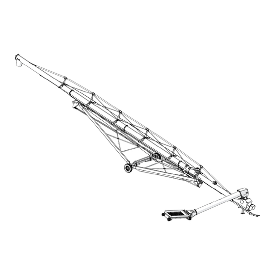
Page 24: Features
3. FEATURES MKX16, X16, HX16, GMX16 SERIES – SWING-AWAY GRAIN AUGER 3. Features Read this section to familiarize yourself with the basic component names and functions of the auger. Discharge Spout Hydraulic Cylinders Truss Tower Track Lift Arm Cable Adjustment Boot Hydraulic Winch Swing... - Page 25 MKX16, X16, HX16, GMX16 SERIES – SWING-AWAY GRAIN AUGER 3. FEATURES Grain Transfer Boot Features Spout Head Service Cover Hitch Angle Adjuster Spout Head Overflow Panel Clean-Out Hatch Spout Head Jack 10 Grain Transfer Boot Auger Tube Lift Valve 11 Speed Reducer Gearbox PTO Driveline Hitch 12 Manual Holder...
- Page 26 3. FEATURES MKX16, X16, HX16, GMX16 SERIES – SWING-AWAY GRAIN AUGER Grain Hopper Features Spout Head Boot Main Auger Swing Auger Power Swing Remote Transmitter Power Swing Drive Wheels Cleanout Hatch Flights and Flight Guarding Intake Hopper Grain Hopper Lifted into Transport Position Winch Cable and Hook Safety Chain and Hook 30869 R11...
-
Page 27: Assembly
Take pictures of shipments prior to, or just after, unloading if there are any damages. Report missing or damaged parts immediately to ensure that proper credit is received from AGI or your representative, and to ensure that any missing parts can be shipped quickly to avoid holding up the assembly process. -
Page 28: Before You Begin
Otherwise, use some form of shim to keep the tubes level across all of the support stands. Important Strap tubes to the support stands to prevent the tubes from rolling off the stands. Figure 1. Upper Auger Tube Sections (All Models) AGI DECAL UPPER TUBE 40” (102 cm) MODEL/SIZE DECAL UPPER MIDDLE TUBE 78”... - Page 29 MKX16, X16, HX16, GMX16 SERIES – SWING-AWAY GRAIN AUGER 4. ASSEMBLY Figure 2. 85’ Auger Tube Sections BRAND DECAL MIDDLE TUBE 170” (432 cm) LOWER TUBE Figure 3. 105’ Auger Tube Sections MIDDLE TUBE BRAND DECAL LOWER MIDDLE TUBE 15” (38 cm) LOWER TUBE Figure 4.
- Page 30 4. ASSEMBLY MKX16, X16, HX16, GMX16 SERIES – SWING-AWAY GRAIN AUGER Apply the Logo and Model Decals on the Auger Tubes Important Do not cover any existing safety or instruction decals with the model decals. 1. Prepare surface by cleaning thoroughly with soap and water. Surface must be clean and free of dirt, grime, rust and oil.
-
Page 31: Connect Auger Tubes
MKX16, X16, HX16, GMX16 SERIES – SWING-AWAY GRAIN AUGER 4. ASSEMBLY 4.4.2 Connect Auger Tubes Important Always strap tubes to the support stands to prevent the tubes from rolling off the stands. Note Assemble the auger tube starting with the discharge section and working toward the intake section. 1. - Page 32 4. ASSEMBLY MKX16, X16, HX16, GMX16 SERIES – SWING-AWAY GRAIN AUGER Figure 6. Track-to-Flange Tube Section Connection 30869 R11...
-
Page 33: Hydraulic Lift Cylinders
MKX16, X16, HX16, GMX16 SERIES – SWING-AWAY GRAIN AUGER 4. ASSEMBLY 4.5. Hydraulic Lift Cylinders 4.5.1 Install the 85' Hydraulic Lift Cylinders 1. Identify the tube section where the hydraulic lift cylinders install, and note the location of the cylinder mounts. - Page 34 4. ASSEMBLY MKX16, X16, HX16, GMX16 SERIES – SWING-AWAY GRAIN AUGER Figure 7. Installing the Lift Cylinders (85') 30869 R11...
-
Page 35: Install The 105'/125' Hydraulic Lift Cylinders
MKX16, X16, HX16, GMX16 SERIES – SWING-AWAY GRAIN AUGER 4. ASSEMBLY 4.5.2 Install the 105'/125' Hydraulic Lift Cylinders 1. Identify the tube section where the hydraulic lift cylinders install, and note the location of the tube cylinder mounts. 2. Ensure that the tube cylinder mounts are facing down. 3. -
Page 36: Install The Track Shoe And Track Stop
4. ASSEMBLY MKX16, X16, HX16, GMX16 SERIES – SWING-AWAY GRAIN AUGER Table 4 Install the 105'/125' Hydraulic Lift Cylinders (continued) Description Quantity Item 1/2 x 1-3/4” bolt 1/2” lock nut Half clamp Figure 8. Installing the Lift Cylinders (105'/125') 4.6. Install the Track Shoe and Track Stop 1. - Page 37 MKX16, X16, HX16, GMX16 SERIES – SWING-AWAY GRAIN AUGER 4. ASSEMBLY Figure 9. Track Stop Positions 125' MODEL 105' MODEL 85' MODEL INTAKE END SPOUT END Table 5. Track Shoe and Track Stop Description Quantity Item Track shoe Track stop 3/4”...
-
Page 38: Install The Boot On The Auger Tube
4. ASSEMBLY MKX16, X16, HX16, GMX16 SERIES – SWING-AWAY GRAIN AUGER 4.7. Install the Boot on the Auger Tube Note • The boot lower gearbox is sent from the factory filled half way with gear oil (1.7 L [1.8 qt]). Before further assembly, check oil level to make certain the gearbox is half full. -
Page 39: Assemble The Pto Shield Assembly
MKX16, X16, HX16, GMX16 SERIES – SWING-AWAY GRAIN AUGER 4. ASSEMBLY Figure 11. Install Boot on Auger Tube 4.8. Assemble the PTO Shield Assembly 1. As shown in Figure 12, align the PTO shield front on the PTO shield rear and secure it with three 5/16” x 3/ 4”... -
Page 40: Install The Speed Reducer On The Boot
4. ASSEMBLY MKX16, X16, HX16, GMX16 SERIES – SWING-AWAY GRAIN AUGER Figure 12. Assemble the PTO Shield Assembly 4.9. Install the Speed Reducer on the Boot 1. Lift the speed reducer and carefully slide it over the gearbox and lower flighting shafts and against the face of the boot. - Page 41 MKX16, X16, HX16, GMX16 SERIES – SWING-AWAY GRAIN AUGER 4. ASSEMBLY Table 8. Install the Speed Reducer on the Boot Description Quantity Item Speed reducer Lower gearbox shaft Lower flight shaft PTO driveline strap PTO shield 1/2” x 11-1/2” GR8 bolts 1/2”...
- Page 42 4. ASSEMBLY MKX16, X16, HX16, GMX16 SERIES – SWING-AWAY GRAIN AUGER Figure 13. Installing the Speed Reducer Figure 14. Install the Shaft Square Keys and Lower Flight Stop 30869 R11...
-
Page 43: Install The Boot Tow Bar
MKX16, X16, HX16, GMX16 SERIES – SWING-AWAY GRAIN AUGER 4. ASSEMBLY 4.10. Install the Boot Tow Bar 1. Insert the tow bar into the boot channel (see Figure 15), and secure the back end loosely with a 3/4” x 6-1/2” bolt and 3/4” lock nut through the hole in the boot channel. 2. -
Page 44: Install The Discharge Spout
4. ASSEMBLY MKX16, X16, HX16, GMX16 SERIES – SWING-AWAY GRAIN AUGER 4.11. Install the Discharge Spout 1. Align the discharge spout over the opening in the upper tube. 2. Attach the discharge spout with two 5/8” x 3” GR8 bolts and 5/8” lock nuts on each side. Table 10. -
Page 45: Install Truss Support Towers And Truss Tubes
MKX16, X16, HX16, GMX16 SERIES – SWING-AWAY GRAIN AUGER 4. ASSEMBLY Figure 17. Setting the Thrust Adjuster 4.13. Install Truss Support Towers and Truss Tubes Due to rigidity of the tubular trussing, do not put an upward bow in the auger. Assemble trussing with main auger tube straight/level and well supported over its length. - Page 46 4. ASSEMBLY MKX16, X16, HX16, GMX16 SERIES – SWING-AWAY GRAIN AUGER 6. Tighten all truss, tube, and cross-brace bolts and nuts, but do not tighten the 1” hex nuts on the truss adjust tubes. 7. Install pairs of cross-brace clamps where the cross-brace tubes cross in an ”X” pattern using two 7/16” x 1-1/ 4”...
- Page 47 MKX16, X16, HX16, GMX16 SERIES – SWING-AWAY GRAIN AUGER 4. ASSEMBLY Figure 18. 85' Truss Tower Brackets HIGH HIGH HIGH HIGH 30869 R11...
- Page 48 4. ASSEMBLY MKX16, X16, HX16, GMX16 SERIES – SWING-AWAY GRAIN AUGER Figure 19. 105' Truss Tower Brackets HIGH HIGH HIGH HIGH HIGH HIGH 30869 R11...
- Page 49 MKX16, X16, HX16, GMX16 SERIES – SWING-AWAY GRAIN AUGER 4. ASSEMBLY Figure 20. 125' Truss Tower Brackets HIGH HIGH HIGH HIGH HIGH HIGH HIGH HIGH 30869 R11...
- Page 50 4. ASSEMBLY MKX16, X16, HX16, GMX16 SERIES – SWING-AWAY GRAIN AUGER Figure 21. 85' Truss Tubes 30869 R11...
- Page 51 MKX16, X16, HX16, GMX16 SERIES – SWING-AWAY GRAIN AUGER 4. ASSEMBLY Figure 22. 105' Truss Tubes 30869 R11...
- Page 52 4. ASSEMBLY MKX16, X16, HX16, GMX16 SERIES – SWING-AWAY GRAIN AUGER Figure 23. 125' Truss Tubes 30869 R11...
-
Page 53: Install Truss Cables
MKX16, X16, HX16, GMX16 SERIES – SWING-AWAY GRAIN AUGER 4. ASSEMBLY 4.14. Install Truss Cables Figure 24 on page 55 for details (85' model shown, other models are similar). 1. Thread truss cable through eyebolts and double-back a minimum of 15-1/4" (39 cm) of cable. Secure the cable in place by installing and tightening three 1/2"... - Page 54 4. ASSEMBLY MKX16, X16, HX16, GMX16 SERIES – SWING-AWAY GRAIN AUGER Table 12. Truss Cables Parts Reference Description Item 3/4'' x 11-1/2'' Eyebolt 3/4” Lock nut 1/2” cable Clamp 1/2” x 68’ x 2 Cable 1/2” x 90’ x 2 Cable 1/2”...
- Page 55 MKX16, X16, HX16, GMX16 SERIES – SWING-AWAY GRAIN AUGER 4. ASSEMBLY Figure 24. Truss Cables 30869 R11...
-
Page 56: Assemble The Lower Frame
4. ASSEMBLY MKX16, X16, HX16, GMX16 SERIES – SWING-AWAY GRAIN AUGER 4.15. Assemble the Lower Frame 1. Fasten the lower reach arms to the axle with four 3/4" x 2" bolts and lock nuts on each side. Tighten securely. Note Insert a punch tool (P) in the middle hole to help align the four bolt holes. - Page 57 MKX16, X16, HX16, GMX16 SERIES – SWING-AWAY GRAIN AUGER 4. ASSEMBLY 3. Install the stabilizer braces on either side of the short cross member with a single 5/8” x 2” bolt and lock nut per side. Leave loose until the other ends of the stabilizer braces are connected in Section 4.16 –...
-
Page 58: Connect The Auger Tube To The Frame
4. ASSEMBLY MKX16, X16, HX16, GMX16 SERIES – SWING-AWAY GRAIN AUGER 4.16. Connect the Auger Tube to the Frame 1. Raise the discharge end of auger (e.g. with a front end loader and a strong sling, or with a chain or block and tackle). - Page 59 MKX16, X16, HX16, GMX16 SERIES – SWING-AWAY GRAIN AUGER 4. ASSEMBLY Table 14. Parts Required to Connect the Auger Tube to the Frame Item Description Quantity Stabilizer Bracket Tube Frame Pin 7/16” x 3-1/2” GR5 Bolt 7/16” Lock nut Axle Frame Pin 1/2”...
- Page 60 4. ASSEMBLY MKX16, X16, HX16, GMX16 SERIES – SWING-AWAY GRAIN AUGER Figure 26. Connecting the Auger Tube to the Frame 30869 R11...
-
Page 61: Install Lift Cylinder Cables To The Lift Assist
MKX16, X16, HX16, GMX16 SERIES – SWING-AWAY GRAIN AUGER 4. ASSEMBLY 4.17. Install Lift Cylinder Cables to the Lift Assist Track shoe must rest against track stop when adjusting cable. If this isn’t done, the auger can raise higher than designed to lift, resulting in damage to auger and possible injury to personnel. - Page 62 4. ASSEMBLY MKX16, X16, HX16, GMX16 SERIES – SWING-AWAY GRAIN AUGER Figure 27. Connecting the Lift Cylinder Cables 85’ MODEL 105/125’ MODELS 30869 R11...
-
Page 63: Connect Hydraulic Hoses And Ball Valve
MKX16, X16, HX16, GMX16 SERIES – SWING-AWAY GRAIN AUGER 4. ASSEMBLY 4.18. Connect Hydraulic Hoses and Ball Valve Table 15. Hydraulic Hoses Hose Description Usage Hydraulic Pressure 85 HOSE, 1/2” x 228” 85 HOSE, 1/2” x 396” Hydraulic Return Hydraulic Pressure 105 HOSE, 1/2”... - Page 64 4. ASSEMBLY MKX16, X16, HX16, GMX16 SERIES – SWING-AWAY GRAIN AUGER 7. Tighten hydraulic hose catch snugly enough to hold hoses in place. (See Figure 32). 8. Run both hoses straight down the side of the auger to the ball valve location on the boot, fastening the hoses at each available hose catch.
- Page 65 MKX16, X16, HX16, GMX16 SERIES – SWING-AWAY GRAIN AUGER 4. ASSEMBLY Table 16. Lift Cylinder Hydraulic Hoses and Fittings (85') Description Number Cap End of Cylinders Lower End (intake) Fluid Return Hose Pressure Hose Cylinder 1 Cylinder 3 Cylinder 2 Rod End of Cylinders Upper End (discharge) Figure 29.
- Page 66 4. ASSEMBLY MKX16, X16, HX16, GMX16 SERIES – SWING-AWAY GRAIN AUGER Table 17. Lift Cylinder Hydraulic Hoses and Fittings (105'/125') Description Number Cap End of Cylinders Lower End (intake) Pressure Hose Fluid Return Hose Cylinder 1 Cylinder 2 Upper End (discharge) Rod End of Cylinders 30869 R11...
- Page 67 MKX16, X16, HX16, GMX16 SERIES – SWING-AWAY GRAIN AUGER 4. ASSEMBLY Figure 30. Hydraulic Diagram (85') 30869 R11...
- Page 68 4. ASSEMBLY MKX16, X16, HX16, GMX16 SERIES – SWING-AWAY GRAIN AUGER Table 18. Hydraulic Diagram (85') Description Number Discharge Intake Cylinder 1 Cylinder 2 Cylinder 3 3/8” Elbow Fitting 3/8” Tee Fitting Short Hydraulic Hose, 32” Short Hydraulic Hose, 16” Long Hydraulic Lift Hose, Pressure (with ball valve and 3/8”...
- Page 69 MKX16, X16, HX16, GMX16 SERIES – SWING-AWAY GRAIN AUGER 4. ASSEMBLY Figure 31. Hydraulic Diagram (105'/125') 30869 R11...
- Page 70 4. ASSEMBLY MKX16, X16, HX16, GMX16 SERIES – SWING-AWAY GRAIN AUGER Table 19. Hydraulic Diagram (105'/125') Description Number Cylinder 1 Cylinder 2 1/2” Elbow Fitting 1/2” Tee Fitting Short Hydraulic Hose, 48” Short Hydraulic Hose, 36” Long Hydraulic Lift Hose, Pressure (with ball valve and 3/8”...
-
Page 71: Connect The Pto Driveline
MKX16, X16, HX16, GMX16 SERIES – SWING-AWAY GRAIN AUGER 4. ASSEMBLY Figure 33. Installing the Ball Valve on the Boot 1/4” X 3/4” BOLTS [9900800] AND 1/4” LOCKNUTS [28449] Table 21. Installing the Ball Valve on the Boot Description Number 1/4”... - Page 72 4. ASSEMBLY MKX16, X16, HX16, GMX16 SERIES – SWING-AWAY GRAIN AUGER Figure 34. Connecting the Stub Shaft to the PTO Driveline 3. Insert the splined end of the PTO stub shaft into the “forward” speed reducer gear box position. 4. Slide the PTO transport saddle through the support strap on the boot and rest the PTO driveline in it. Figure 35.
-
Page 73: Connect The Intake Hopper To The Swing Tube
MKX16, X16, HX16, GMX16 SERIES – SWING-AWAY GRAIN AUGER 4. ASSEMBLY Table 22. PTO Parts and Installation Description Item Forward Reverse 4.20. Connect the Intake Hopper to the Swing Tube Lockout the lifting apparatus before working around or under the raised components. Failure to do so may cause serious personal injury. - Page 74 4. ASSEMBLY MKX16, X16, HX16, GMX16 SERIES – SWING-AWAY GRAIN AUGER 4. Secure the U-joint to the swing flight with a 3/8" set screw, a 5/16" x 2-3/4" bolt, and a lock nut. 5. Slide the transition flight shaft into the U-joint. Figure 36.
- Page 75 MKX16, X16, HX16, GMX16 SERIES – SWING-AWAY GRAIN AUGER 4. ASSEMBLY Figure 37. Connecting the Transition to the Intake Hopper 15,16 15,16 9. Attach the six solid wheels to the four hopper corners with the axle pins and hairpins. There are three height settings (Figure 38)that can be used according to preference.
-
Page 76: Connect The Spout Head To The Grain Transfer Boot
4. ASSEMBLY MKX16, X16, HX16, GMX16 SERIES – SWING-AWAY GRAIN AUGER 4.21. Connect the Spout Head to the Grain Transfer Boot Table 24. Parts Required to Connect the Spout Head to the Boot Description Quantity Item Service Cover Spring Clasps Gearbox Coupler (2A Top, 2B Bottom) 3/8”... -
Page 77: Install The Hopper Lift Arm
MKX16, X16, HX16, GMX16 SERIES – SWING-AWAY GRAIN AUGER 4. ASSEMBLY Figure 39. Connecting the Spout Head to the Boot WELD BETWEEN SHAFT SPLINES GAP BETWEEN SPLINES 4.22. Install the Hopper Lift Arm 1. Determine which side of the auger the hopper will be operating on. Note Feed side of hopper must face the main auger when in transport. -
Page 78: Install The Hydraulic Winch
4. ASSEMBLY MKX16, X16, HX16, GMX16 SERIES – SWING-AWAY GRAIN AUGER Figure 40. Installing the Lift Arm 4.23. Install the Hydraulic Winch 1. Position the hydraulic winch on the winch mounting plate, and secure it using three 3/8" washers and three 3/8"... - Page 79 MKX16, X16, HX16, GMX16 SERIES – SWING-AWAY GRAIN AUGER 4. ASSEMBLY Figure 41. Installing the Hydraulic Winch 5/16” X 1” BOLTS [17125] AND LOCKNUTS [19980] 3/8” LOCK NUTS [17402] HYDRAULIC WINCH LIFT ARM PULLEY GUIDE 3/8” FLAT WASHERS [17392] WINCH MOUNTING POSITION FOR MANUAL WINCH PLATE...
- Page 80 4. ASSEMBLY MKX16, X16, HX16, GMX16 SERIES – SWING-AWAY GRAIN AUGER Figure 43. Installing the Hydraulic Winch Hose Table 25. Installing the Hydraulic Winch Hose Description Item Steel Elbow 90.1 / 2FNPSMX3 / 8MNPT 1/2" x 226" Hydraulic Hose Pioneer Coupler 30869 R11...
-
Page 81: Electric Power Swing Assembly
MKX16, X16, HX16, GMX16 SERIES – SWING-AWAY GRAIN AUGER 4. ASSEMBLY 4.24. Electric Power Swing Assembly 4.24.1 Power Swing Components Figure 44. Electric Power Swing Components Table 26. Electric Power Swing Components Part Description Item Manual Jack Attach Bracket Right-Side Attach Bracket Landing Gear Assembly (Electric) Landing Gear Wheels Receiver Top-Clamp Assembly... - Page 82 4. ASSEMBLY MKX16, X16, HX16, GMX16 SERIES – SWING-AWAY GRAIN AUGER 2. Fasten the jack attach bracket to the swing tube using four 7/16" x 1-1/4" bolts and lock nuts. 3. Slide the upper manual jack attachment onto the manual jack attach pin, and secure using a lynch pin. 4.
- Page 83 MKX16, X16, HX16, GMX16 SERIES – SWING-AWAY GRAIN AUGER 4. ASSEMBLY Figure 45. Attach the Landing Gear to the Tube 30869 R11...
-
Page 84: Install And Connect The Receiver Box
4. ASSEMBLY MKX16, X16, HX16, GMX16 SERIES – SWING-AWAY GRAIN AUGER 4.24.3 Install and Connect the Receiver Box 1. Position the receiver top clamp assembly approximately 24" (61 cm) from the transition attach plate and secure using eight 7/16” x 1-1/4” bolts and lock nuts. Tighten both sides securely. 2. - Page 85 MKX16, X16, HX16, GMX16 SERIES – SWING-AWAY GRAIN AUGER 4. ASSEMBLY b. Place the wire on, and then replace the nut. c. Tighten securely. d. Repeat the same steps for the negative wire and terminal. 7. Route the long electrical cable up the swing tube and secure it using an insulated clamp, a 1/4” x 3/4” bolt, and a 1/4”...
- Page 86 4. ASSEMBLY MKX16, X16, HX16, GMX16 SERIES – SWING-AWAY GRAIN AUGER Figure 47. Connecting the Receiver Box QUICK CONNECT POSITIVE WIRE WITH RED BOOT CONNECTS TO POSITIVE MOTOR TERMINAL. NEGATIVE WIRE CONNECTS TO NEGATIVE MOTOR TERMINAL. 30869 R11...
- Page 87 MKX16, X16, HX16, GMX16 SERIES – SWING-AWAY GRAIN AUGER 4. ASSEMBLY Table 29. Connecting the Receiver Box to the Motors and Battery Part Description Item 5/8” x 1/2” Insulated Clamp 1/4” x 3/4” Bolt 1/4” Lock nut Quick Connect Positive wire Negative wire Long Electrical Cable 9, 13...
-
Page 88: Install The Hitch Jack
4. ASSEMBLY MKX16, X16, HX16, GMX16 SERIES – SWING-AWAY GRAIN AUGER Figure 48. Power Swing Wiring Diagram 4.25. Install the Hitch Jack The jack is attached to the auger with a pin at the pivot point. To install: 1. Elevate the auger boot (intake end) approximately 2’ (5.08 cm) with a front- end loader and sling, and install the jack in a vertical position. -
Page 89: Install The Manual Container
MKX16, X16, HX16, GMX16 SERIES – SWING-AWAY GRAIN AUGER 4. ASSEMBLY 4.26. Install the Manual Container Mount the plastic manual holder directly to the boot (as shown below) using three self-tapping screws. Figure 49. Installing the Plastic Manual Container 4.27. Install Work Lights 1. -
Page 90: Install Transport Lights
4. ASSEMBLY MKX16, X16, HX16, GMX16 SERIES – SWING-AWAY GRAIN AUGER 4.28. Install Transport Lights 1. Attach the light mount assemblies to the axle with 7/16" x 1-1/4" bolts and lock nuts, then plug the transport light connector to the wiring harness connector. Ensure that the connectors are fully engaged. 2. - Page 91 MKX16, X16, HX16, GMX16 SERIES – SWING-AWAY GRAIN AUGER 4. ASSEMBLY 4. Run the wiring harness down the lower tube along the hydraulic hoses to the boot assembly and secure using zip ties. 5. Plug the wiring harness connector into the work light kit connector. Ensure that the connectors are fully engaged.
-
Page 92: Install The Retroreflective Strips
4. ASSEMBLY MKX16, X16, HX16, GMX16 SERIES – SWING-AWAY GRAIN AUGER 4.29. Install the Retroreflective Strips Spout 2" (5.1 cm) Lower and Upper Arms 85' Models: 12" (30.5 cm) 85' Models: 25" (63.5 cm) 105' Models: 63" (160 cm) 105' Models: 34" (86.4 cm) 125' Models: 135"... -
Page 93: Specifications
MKX16, X16, HX16, GMX16 SERIES – SWING-AWAY GRAIN AUGER 5. SPECIFICATIONS 5. Specifications Specification 16–85 16–105 16–125 16" (40.6 cm) Tube Size CAPACITIES Unloading Rate 23000 Bu/Hr TRANSPORT DIMENSIONS Length 105' 125' 13'4"/16'9" Width Height (4.27 m) (4.27 m) (4.88 m) DISCHARGE CLEARANCE DIMENSIONS 12'3"... - Page 94 5. SPECIFICATIONS MKX16, X16, HX16, GMX16 SERIES – SWING-AWAY GRAIN AUGER Specification X-Tend 16 Tractor Hydraulic Flow Adjust to 8 GPM 1000 rpm Tractor PTO Speed Hopper Height 14" Hopper Length 68" Hopper Width 46" Total Swing Weight 2100 lbs Weight on Lift Arm 1300 lbs Power Swing Tire Pressure...
-
Page 95: Appendix
Tighten all bolts to the torque specified, unless otherwise noted. Check tightness periodically, using Table 30 as a guide. Replace the hardware with the same strength bolt, contact AGI if you are unsure. Table 30. Recommended Bolt Torque Recommended Torque (ft-lb) Threads... -
Page 96: Agi Limited Warranty
7. AGI Limited Warranty This warranty relates to AGI Augers (the “Product”) sold by AGI, (referred to herein as the “Seller”) and applies only to the first user of the Product (meaning a purchaser directly from the Seller or from an authorized dealer or distributor of the Product, referred to herein as the “Buyer”). - Page 97 MKX16, X16, HX16, GMX16 SERIES – SWING-AWAY GRAIN AUGER 7. AGI LIMITED WARRANTY 30869 R11...
- Page 98 AGI is a leading provider of equipment solutions for agriculture bulk commodities including seed, fertilizer, grain, and feed systems with a growing platform in providing equipment and solutions for food processing facilities. AGI has manufacturing facilities in Canada, the United States, the United Kingdom, Brazil, South Africa, India and Italy and distributes its products globally.
Need help?
Do you have a question about the MKX16 Series and is the answer not in the manual?
Questions and answers