Table of Contents
Advertisement
Quick Links
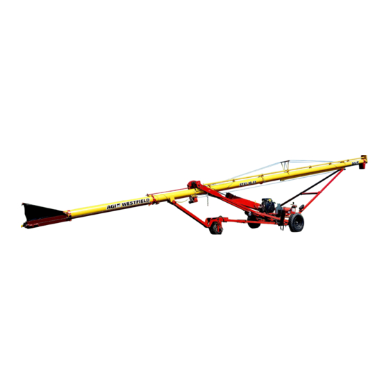
Self-Propelled Auger Kit
Portable Grain Auger
Assembly Manual
This manual applies to:
AGI Westfield STX2 8/10 (31/36/41/46/51)
AGI XTA 8/10 (31/36/41/46/51)
AGI Hutchinson STX2 8/10 (31/36/41/46/51)
AGI Mayrath STX2 8/10 (31/36/41/46/51)
Read this manual before using product. Failure to
follow instructions and safety precautions can
result in serious injury, death, or property
damage. Keep manual for future reference.
LOOKING FOR PARTS?
Check out our online
Parts Catalog!
Part Number: 31037 R4
Revised: October 2024
Original Instructions
Advertisement
Table of Contents

Related Manuals for AGI Westfield STX2 8/10


Summary of Contents for AGI Westfield STX2 8/10
- Page 1 Self-Propelled Auger Kit Portable Grain Auger Assembly Manual This manual applies to: AGI Westfield STX2 8/10 (31/36/41/46/51) AGI XTA 8/10 (31/36/41/46/51) AGI Hutchinson STX2 8/10 (31/36/41/46/51) AGI Mayrath STX2 8/10 (31/36/41/46/51) LOOKING FOR PARTS? Check out our online Parts Catalog! Read this manual before using product.
- Page 2 New in this Manual The following changes have been made in this revision of the manual: Description Section Added new section for installing the axle ring gear. Section 3.9 – Install the Ring Gear on page 20 Updated the steel fitting for the hydraulic cylinder. Section 3.14 –...
-
Page 3: Table Of Contents
SELF-PROPELLED AUGER KIT – PORTABLE GRAIN AUGER CONTENTS 1. Introduction ............................4 2. Safety............................... 5 2.1 Safety Alert Symbol and Signal Words..................5 2.2 General Safety Information....................... 5 2.3 Rotating Parts Safety......................... 5 2.4 Hydraulic Winch Safety ......................6 2.5 Drives and Lockout Safety......................6 2.5.1 Gas Engine Safety....................... -
Page 4: Introduction
Before assembling, please read this manual. Familiarize yourself with the process and the necessary precautions for efficient and safe assembly of this AGI Self-Propelled Auger Kit. Everyone present at the assembly site is required to be familiar with all safety precautions. -
Page 5: Safety
• Follow a health and safety program for your worksite. Contact your local occupational health and safety organization for information. • Contact your local representative or AGI if you need assistance or additional information. • Always follow applicable local codes and regulations. -
Page 6: Hydraulic Winch Safety
2. SAFETY SELF-PROPELLED AUGER KIT – PORTABLE GRAIN AUGER 2.4. Hydraulic Winch Safety When Equipped: • Keep away from rotating cable drum and winch cable. Do not touch or grab cable while winch is being operated or use hands to guide the cable. •... -
Page 7: Hydraulic Power Safety
SELF-PROPELLED AUGER KIT – PORTABLE GRAIN AUGER 2. SAFETY 2.5.2 Hydraulic Power Safety Power Source • Refer to the rules and regulations applicable to the power source operating the hydraulic system. • Do not connect or disconnect hydraulic lines while system is under pressure. -
Page 8: Tire Safety
2. SAFETY SELF-PROPELLED AUGER KIT – PORTABLE GRAIN AUGER 2.6. Tire Safety Failure to follow proper procedures when mounting a tire on a wheel or rim can produce an explosion that may result in serious injury or death. • DO NOT attempt to mount a tire unless you have the proper equipment and experience to do the job. -
Page 9: Safety Equipment
SELF-PROPELLED AUGER KIT – PORTABLE GRAIN AUGER 2. SAFETY Coveralls • Wear coveralls to protect skin. Hard Hat • Wear a hard hat to help protect your head. 2.8. Safety Equipment The following safety equipment should be kept on site. Fire Extinguisher •... -
Page 10: Safety Decal Locations And Details
2. SAFETY SELF-PROPELLED AUGER KIT – PORTABLE GRAIN AUGER 2.9.2 Safety Decal Locations and Details Replicas of the safety decals that are attached to the self-propelled auger kit and their messages are shown in the figure(s) that follow. Safe operation and use of the self-propelled auger kit requires that you familiarize yourself with the various safety decals and the areas or particular functions that the decals apply to, as well as the safety precautions that must be taken to avoid serious injury, death, or damage. - Page 11 SELF-PROPELLED AUGER KIT – PORTABLE GRAIN AUGER 2. SAFETY Table 1. Safety Decals Part Number Description 20806 WARNING HIGH PRESSURE FLUID HAZARD Hydraulic fluid can cause serious injury if it penetrates the skin. If it does, see a doctor immediately. •...
-
Page 12: Assembly
Report missing or damaged parts immediately to ensure that proper credit is received from AGI or your representative, and to ensure that any missing parts can be shipped quickly to avoid holding up the assembly process. -
Page 13: Hydraulic Fittings And Bolt Tightening
SELF-PROPELLED AUGER KIT – PORTABLE GRAIN AUGER 3. ASSEMBLY 3.4. Hydraulic Fittings and Bolt Tightening Remember the following basic considerations when tightening hydraulic fittings and bolts: • Tighten all fasteners to the torque specified in Section 4.1 – Bolt Torque on page 48. - Page 14 3. ASSEMBLY SELF-PROPELLED AUGER KIT – PORTABLE GRAIN AUGER steel fitting, 3/4" HB x 10 MORB steel fitting, 8 MORB x 1/2" FNPSM pump pulley, 4-1/2" x 1-1/8" single square key, 1/4" x 3" 31037 R4...
- Page 15 SELF-PROPELLED AUGER KIT – PORTABLE GRAIN AUGER 3. ASSEMBLY Assembly Note: • Rotate the pump handle clockwise to apply tension to the pump belt and pull down the handle to lock the belt in place. pump belt, BX35 pump handle 31037 R4...
-
Page 16: Install The Hydraulic Oil Tank
3. ASSEMBLY SELF-PROPELLED AUGER KIT – PORTABLE GRAIN AUGER 3.6. Install the Hydraulic Oil Tank 7 " 28 " Assembly Notes: • Place the first hydraulic tank mount 7" from the end of the tube. • Place the second hydraulic tank mount 28" from the end of the tube. lower support frame, right square U-bolt, 3/8"... - Page 17 SELF-PROPELLED AUGER KIT – PORTABLE GRAIN AUGER 3. ASSEMBLY Assembly Note: • Ensure the cap is located on the raised side. hydraulic tank lock nut, 1/4" square U-bolt, 1/4" x 7-1/4" x 7-5/8" 31037 R4...
-
Page 18: Install The Hydraulic Filter
3. ASSEMBLY SELF-PROPELLED AUGER KIT – PORTABLE GRAIN AUGER 3.7. Install the Hydraulic Filter Assembly Note: • The hydraulic hoses MUST be installed to ensure that the oil flows to the tank, in the same direction as the arrow on the filter head. hydraulic filter head lock washer, 1/4"... -
Page 19: Install The Cushion Block
SELF-PROPELLED AUGER KIT – PORTABLE GRAIN AUGER 3. ASSEMBLY 3.8. Install the Cushion Block cushion block steel elbow, 90, 6 MNPT x 6 FNPSM bolt, 5/16" x 3/4" steel fitting, 3/8" MNPT x 3/8" FNPSM lock washer, 5/16" 31037 R4... -
Page 20: Install The Ring Gear
3. ASSEMBLY SELF-PROPELLED AUGER KIT – PORTABLE GRAIN AUGER 3.9. Install the Ring Gear Assembly Notes: • Check that air pressure in the tires match pressure indicated on the tire sidewall. • Torque the wheel nuts to 80 ft·lb ± 10 ft·lb (108.5 N·m ± 13.5 N·m) using the pattern shown. wheel ring gear wheel nut, 1/2"... -
Page 21: Install The Over-Center Drive
SELF-PROPELLED AUGER KIT – PORTABLE GRAIN AUGER 3. ASSEMBLY 3.10. Install the Over-Center Drive 1. Position the axle cap of the over-center drive assembly squarely on the axle tube. 2. With the pinion gear flush with the ring gear, bolt the axle cap to the axle tube using four carriage bolts and lock nuts. -
Page 22: Adjust The Pinion Gear
3. ASSEMBLY SELF-PROPELLED AUGER KIT – PORTABLE GRAIN AUGER 3.11. Adjust the Pinion Gear Failure to ensure proper gear meshing will result in gear damage. The pinion gear should mesh with the ring gear to provide maximum tooth contact. Insufficient meshing •... -
Page 23: Install The Hydraulic Winch
SELF-PROPELLED AUGER KIT – PORTABLE GRAIN AUGER 3. ASSEMBLY 3.12. Install the Hydraulic Winch hydraulic winch assembly lock nut, 3/8" steel fitting, 90, 6 MNPT x 6 FNPSM flat washer, 3/8" 31037 R4... -
Page 24: Connect The Lift Cable
3. ASSEMBLY SELF-PROPELLED AUGER KIT – PORTABLE GRAIN AUGER 3.13. Connect the Lift Cable Important Make sure there is a minimum of three wraps of cable on the winch drum when the auger is in transport position. 1. Pull cable to the winch. 2. -
Page 25: Install The Undercarriage
SELF-PROPELLED AUGER KIT – PORTABLE GRAIN AUGER 3. ASSEMBLY 3.14. Install the Undercarriage Important When assembling the frame pipes, ram extension, and cylinder under the auger, the components should form a straight line from the axle to the ram mount when the auger is fully lowered. Assembly Note: •... - Page 26 3. ASSEMBLY SELF-PROPELLED AUGER KIT – PORTABLE GRAIN AUGER SP reach arm flat washer, 3/8" V-frame lock nut, 3/8" bolt, 3/8" x 1-1/4" 31037 R4...
- Page 27 SELF-PROPELLED AUGER KIT – PORTABLE GRAIN AUGER 3. ASSEMBLY axle lock nut, 1/2" SP reach arm bolt, 1/2" x 1-3/4" 31037 R4...
- Page 28 3. ASSEMBLY SELF-PROPELLED AUGER KIT – PORTABLE GRAIN AUGER SP RAM mount hydraulic cylinder bolt, 1/2" x 2-1/4" bolt, 1/2" x 1-3/4" lock nut, 1/2" lock nut, 1/2" RAM extension RAM mount A-frame clamp bolt, 3/8" x 2-1/2" bolt, 3/8" x 1-1/4" steel fitting, 90, 3/8 FSNPSM x 3/8 MORB lock nut, 3/8"...
- Page 29 SELF-PROPELLED AUGER KIT – PORTABLE GRAIN AUGER 3. ASSEMBLY Reference Dimensions 23 " Auger 3" 6" 2-1/2" 7" 21-1/2" 31037 R4...
-
Page 30: Install The Cross Brace Pipes
3. ASSEMBLY SELF-PROPELLED AUGER KIT – PORTABLE GRAIN AUGER 3.15. Install the Cross Brace Pipes 31'/36' Augers cross brace pipe lock nut, 3/8" cross brace clamp band V-frame bolt, 3/8" x 2" bolt, 3/8" x 1-1/4" 31037 R4... - Page 31 SELF-PROPELLED AUGER KIT – PORTABLE GRAIN AUGER 3. ASSEMBLY 41'/46'/51' Augers Assembly Note: • Be sure to mount one cross brace pipe to the top side of the v-frame tab and the second cross brace pipe to the bottom side. cross brace pipe lock nut, 3/8"...
-
Page 32: Install The Control Ring
3. ASSEMBLY SELF-PROPELLED AUGER KIT – PORTABLE GRAIN AUGER 3.16. Install the Control Ring 90 " control ring Table 2. Reference Dimensions Auger 50" 69" 90" 90" 90" 31037 R4... - Page 33 SELF-PROPELLED AUGER KIT – PORTABLE GRAIN AUGER 3. ASSEMBLY half clamp valve mount with 3-spool valve bolt, 7/16" x 1-1/4" half clamp lock nut, 7/16" 3-spool valve bolt, M8 x 1.25 x 25 control handle lock washer, 5/16" 31037 R4...
- Page 34 3. ASSEMBLY SELF-PROPELLED AUGER KIT – PORTABLE GRAIN AUGER steel elbow, 45, 6 MORB x 6 MJIC steel elbow, 90, 10 MORB x 1/2 NSPM steel elbow, 90, 8 MORB x 8 NFPT 31037 R4...
-
Page 35: Attach The Transport Chain
SELF-PROPELLED AUGER KIT – PORTABLE GRAIN AUGER 3. ASSEMBLY 3.17. Attach the Transport Chain Assembly Note: • If necessary, the transport chain assembly can be shortened. – Remove mid link from chain. – Attach mid link to the appropriate chain link. transport chain mid link 31037 R4... -
Page 36: Install The Line Blocks
3. ASSEMBLY SELF-PROPELLED AUGER KIT – PORTABLE GRAIN AUGER 3.18. Install the Line Blocks line block flat washer, 3/8" bolt, 3/8" x 1-3/4" lock nut, 3/8" 31037 R4... -
Page 37: Attach The Hydraulic Hoses
SELF-PROPELLED AUGER KIT – PORTABLE GRAIN AUGER 3. ASSEMBLY 3.19. Attach the Hydraulic Hoses 31037 R4... - Page 38 3. ASSEMBLY SELF-PROPELLED AUGER KIT – PORTABLE GRAIN AUGER Hydraulic Hoses Length Item Hose Ends 3/4" x 78" 1/2 MNPT x 1/2 MNPT 1/2" x 173" 1/2" x 192" 1/2" x 220" 1/2" x 252" 1/2" x 300" 1/2 MNPT x 1/2 MNPT 1/2"...
- Page 39 SELF-PROPELLED AUGER KIT – PORTABLE GRAIN AUGER 3. ASSEMBLY Hose Routing Serious operator injury could occur if the transport unit and hydraulic hoses are not assembled correctly. If necessary, disconnect the hoses and re-assemble. The SP Transport unit MUST operate as indicated on the control panel decal. The auger MUST move in the direction that the handle is moved.
- Page 40 3. ASSEMBLY SELF-PROPELLED AUGER KIT – PORTABLE GRAIN AUGER Hydraulic Hoses E1 and E2 Note Route hoses E1 and E2 to the valve through the closest lower frame. 31037 R4...
- Page 41 SELF-PROPELLED AUGER KIT – PORTABLE GRAIN AUGER 3. ASSEMBLY Hydraulic Hose A Note Route hose A under the engine slider assembly along the lower frame. 31037 R4...
- Page 42 3. ASSEMBLY SELF-PROPELLED AUGER KIT – PORTABLE GRAIN AUGER Hydraulic Hose I 31037 R4...
- Page 43 SELF-PROPELLED AUGER KIT – PORTABLE GRAIN AUGER 3. ASSEMBLY Hydraulic Hose C Note Route hose C to the valve through the lower frame. 31037 R4...
- Page 44 3. ASSEMBLY SELF-PROPELLED AUGER KIT – PORTABLE GRAIN AUGER Hydraulic Hose B Note Route hose B to the valve through the lower frame. 31037 R4...
- Page 45 SELF-PROPELLED AUGER KIT – PORTABLE GRAIN AUGER 3. ASSEMBLY Hydraulic Hoses F1 and F2 31037 R4...
- Page 46 3. ASSEMBLY SELF-PROPELLED AUGER KIT – PORTABLE GRAIN AUGER Hydraulic Hoses D1 and D2 31037 R4...
- Page 47 SELF-PROPELLED AUGER KIT – PORTABLE GRAIN AUGER 3. ASSEMBLY Hydraulic Valve 31037 R4...
-
Page 48: Appendix
Tighten all bolts to the torque specified, unless otherwise noted. Check tightness periodically, using Table 3 as a guide. Replace the hardware with the same strength bolt, contact AGI if you are unsure. Table 3. Recommended Bolt Torque Recommended Torque (ft-lb) Threads... -
Page 49: Fittings Torque Values
SELF-PROPELLED AUGER KIT – PORTABLE GRAIN AUGER 4. APPENDIX 4.2. Fittings Torque Values These specifications are for carbon steel. With Zinc plating always lubricate threads and seals. For stainless steel, use the high value of the torque range of steel. For brass, use 70% of the torque value of steel. For mixed metals, use the torque of the lower of the two metals. - Page 50 4. APPENDIX SELF-PROPELLED AUGER KIT – PORTABLE GRAIN AUGER Table 6 Stud End O-Ring Boss (ORB) SAE (U/UF) – Carbon Steel (continued) Max N-m Tube Size Thread UNF-2A Max ft-lbs 22-24 29-33 9/16" - 18 40-43 49-53 3/4" - 16 43-48 59-64 7/8"...
- Page 51 SELF-PROPELLED AUGER KIT – PORTABLE GRAIN AUGER 4. APPENDIX 31037 R4...
- Page 52 AGI is a leading provider of equipment solutions for agriculture bulk commodities including seed, fertilizer, grain, and feed systems with a growing platform in providing equipment and solutions for food processing facilities. AGI has manufacturing facilities in Canada, the United States, the United Kingdom, Brazil, South Africa, India and Italy and distributes its products globally.
Need help?
Do you have a question about the Westfield STX2 8/10 and is the answer not in the manual?
Questions and answers