Table of Contents
Advertisement
Quick Links
FSA052 and FSA102 Series
Sweep Auger
Assembly, Operation, and Maintenance Instructions
This manual applies to the following models:
FSA05210 – FSA05236
FSA10215 – FSA10236
Read this manual before using product. Failure to
follow instructions and safety precautions can
result in serious injury, death, or property
damage. Keep manual for future reference.
Part Number: 54X4119 R0
Revised: May 2024
Original Instructions
Advertisement
Table of Contents

Related Manuals for AGI EMEA FSA052 Series


Summary of Contents for AGI EMEA FSA052 Series
- Page 1 FSA052 and FSA102 Series Sweep Auger Assembly, Operation, and Maintenance Instructions This manual applies to the following models: FSA05210 – FSA05236 FSA10215 – FSA10236 Read this manual before using product. Failure to Part Number: 54X4119 R0 follow instructions and safety precautions can Revised: May 2024 result in serious injury, death, or property Original Instructions...
- Page 2 This product has been designed and manufactured to meet general engineering standards. Other local regulations may apply and must be followed by the operator. All personnel must be trained in the correct operational and safety procedures for this product. Use the sign-off sheet below to record initial and periodic reviews of this manual with all personnel.
-
Page 3: Table Of Contents
FSA052 AND FSA102 SERIES – SWEEP AUGER CONTENTS 1. Introduction ............................5 1.1 Intended Use ..........................5 1.2 Limitations ..........................6 1.3 Supply Limits..........................6 1.4 Machine Identification ......................7 1.5 Manufacturer Identification...................... 9 2. Safety..............................10 2.1 About Safety Information in this Manual ................10 2.2 Preventing Safety Hazards ...................... - Page 4 FSA052 AND FSA102 SERIES – SWEEP AUGER 7.2.1 Prevention and Protection Against Hazards of Mechanical Origin ......48 7.2.2 Prevention and Protection Against Hazards of Electrical Origin ......48 7.2.3 Prevention and Protection in Respect of Hygiene........... 48 7.2.4 Prevention and Protection Against Risks Caused by Noise ........48 7.2.5 Prevention and Protection Against Explosion Hazards..........
-
Page 5: Introduction
1.1. Intended Use The sweep auger is intended for use as listed below and described throughout this manual. Use in any other way shall void the warranty and invalidate all liability of AGI EMEA for any personal injury or property damage incurred. -
Page 6: Limitations
1. INTRODUCTION FSA052 AND FSA102 SERIES – SWEEP AUGER – Other cereals The Customer assumes full and sole liability if the machine is used to store products other than those listed above, unless such use has been expressly authorised by the Manufacturer. •... -
Page 7: Machine Identification
FSA052 AND FSA102 SERIES – SWEEP AUGER 1. INTRODUCTION 1.4. Machine Identification The identification plate contains the following information: • CE Mark • Manufacturer’s trademark, name and address • Year of manufacturing • Serial number • Model • Description Other data relating to the installed power and supply voltage (voltage and frequency) are shown on the identification plate applied to the electric motor by the motor manufacturer. - Page 8 1. INTRODUCTION FSA052 AND FSA102 SERIES – SWEEP AUGER If the sweep auger is sold according to ATEX requirement, ATEX marking is displayed on the identification plate. Understanding the ATEX code Special condi�ons Category Type of protection Temperature for safe use II2D Ex h III T140°C Db Dust group Group...
-
Page 9: Manufacturer Identification
FSA052 AND FSA102 SERIES – SWEEP AUGER 1. INTRODUCTION 1.5. Manufacturer Identification Name AGI EMEA S.R.L. Head Office Address : Via Bertella 2, 40064 Ozzano dell’Emilia, Bologna, Italy Telephone +39 051 798 107 +39 051 796 300 Email emea@aggrowth.com Website www.aggrowth.com/en-us/regions/agi_emea... -
Page 10: Safety
2. SAFETY FSA052 AND FSA102 SERIES – SWEEP AUGER 2. Safety Good safety practices prevent accidents. Always take time to use the sweep auger safely and don’t shortcut or ignore safety information. Inform others of safety hazards and how to prevent them. 2.1. - Page 11 FSA052 AND FSA102 SERIES – SWEEP AUGER 2. SAFETY Keep the Sweep Auger in Good Condition For safe operation and to prevent unnecessary downtime: • Do not modify the sweep auger. • Maintain the sweep auger and inspect it before using. •...
- Page 12 2. SAFETY FSA052 AND FSA102 SERIES – SWEEP AUGER Keep Away from Rotating Parts To prevent serious injury or death: • Keep body, hair, and clothing away from rotating parts. Enter the Bin Safely To prevent serious injury or death: •...
- Page 13 FSA052 AND FSA102 SERIES – SWEEP AUGER 2. SAFETY Keep Away from Flowing Grain This information may also apply to fertilizer where the silo is intended for fertilizer storage. • Grain flows in a funnel-shaped path when unloading. This vortex of grain behaves very much like a water drain.
- Page 14 2. SAFETY FSA052 AND FSA102 SERIES – SWEEP AUGER Watch for and Keep Away from Bridged Grain This information may also apply to fertilizer where the silo is intended for fertilizer storage. • Never enter a silo from the roof if you don’t know its unloading history. Grain can “bridge”...
- Page 15 FSA052 AND FSA102 SERIES – SWEEP AUGER 2. SAFETY Keep Away from a Vertical Wall of Grain This information may also apply to fertilizer where the silo is intended for fertilizer storage. • Vertical walls of grain are created when the silo is partially empty. Poking at the wall can make the grain avalanche and submerge a person.
- Page 16 2. SAFETY FSA052 AND FSA102 SERIES – SWEEP AUGER Use Electric Motors Safely To prevent electrocution: • Have electric motors and controls installed and serviced by a qualified electrician to meet local codes and standards. • Replace electrical wiring and cords that are worn or are not in good condition. •...
-
Page 17: Safety Decal Locations And Replacements
2. Decide on the position before removing the backing paper. Click the link, scan the QR code, or contact your local AGI representative for free replacements. 3. Align the decal and press the small portion with the exposed sticky backing in place. - Page 18 2. SAFETY FSA052 AND FSA102 SERIES – SWEEP AUGER 350100033 Safety Decals and Part Numbers 350100046 SAFETY INSTRUCTIONS • Read and understand the manual before assembling, operating, or maintaining the equipment. • Only trained personnel may assemble, operate, or maintain the equipment. •...
- Page 19 FSA052 AND FSA102 SERIES – SWEEP AUGER 2. SAFETY 350100033 STAY AWAY FROM ALL AUGERS • Turn off and completely lock out the power. • Place another person outside the steel silo. • Avoid the center of the steel silo. •...
-
Page 20: General Machine Description
3. GENERAL MACHINE DESCRIPTION FSA052 AND FSA102 SERIES – SWEEP AUGER 3. General Machine Description The sweep auger is installed inside a silo to facilitate complete product discharge without the need for personnel entering the silo. The machine comes into operation after unloading the silo by gravity. It conveys the granular product deposited from the peripheral areas towards the center of the silo. -
Page 21: Features
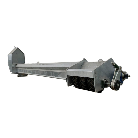
FSA052 AND FSA102 SERIES – SWEEP AUGER 4. FEATURES 4. Features Figure 2. Typical Sweep Auger Description Description Item Item Intermediate Joint Assembly Motor Drive Support Plate Case Feed Foot Second Feed Foot (used for larger models), not shown Spiral Screw 54X4119 R0... -
Page 22: Pre-Assembly
5. PRE-ASSEMBLY FSA052 AND FSA102 SERIES – SWEEP AUGER 5. Pre-Assembly 5.1. Transport and Handling The machine is generally shipped in crates. Read the shipping note to identify the package number and weights. The machine is shipped in wooden crates containing all components except the head and foot, which are placed on special pallets. -
Page 23: Product Storage
FSA052 AND FSA102 SERIES – SWEEP AUGER 5. PRE-ASSEMBLY 5.4. Product Storage If storing components before installation, follow the instructions below to prevent dirt and moisture accumulation, damage, or injury. Damage to components resulting from improper storage is not covered by warranty. -
Page 24: Civil Works
5. PRE-ASSEMBLY FSA052 AND FSA102 SERIES – SWEEP AUGER 5.6. Civil Works For the machine to work correctly and safely inside the silo, it is essential to: • Ensure that the floor flatness complies with the design requirements and is free of irregularities, damage, and fragility. -
Page 25: Provisions To Be Made By The Customer
FSA052 AND FSA102 SERIES – SWEEP AUGER 5. PRE-ASSEMBLY 5.7. Provisions to be Made by the Customer Unless otherwise agreed in the contract, the customer shall be responsible for providing the following: • suitable means of transport • suitable lifting and handling equipment and qualified operators to unload containers •... -
Page 26: Environmental Conditions For Installation
5. PRE-ASSEMBLY FSA052 AND FSA102 SERIES – SWEEP AUGER The Customer is solely responsible for the adequacy and efficiency of the general electrical system and any additional equipment that may be required to interrupt the supply of electricity in the event of break downs. For example: •... -
Page 27: Fire Hazards
FSA052 AND FSA102 SERIES – SWEEP AUGER 5. PRE-ASSEMBLY 5.8.4 Fire Hazards Keep the area surrounding the machine free of inflammable objects such as pallets and wood in general, solvents, lubricants, combustibles or any other inflammable substance to prevent them from fueling a fire. 5.8.5 Explosion Hazard In certain conditions, grain dust can be highly explosive. - Page 28 5. PRE-ASSEMBLY FSA052 AND FSA102 SERIES – SWEEP AUGER Thermistors – Special requirements for safe use X The thermistors of the electric motor must be connected by the user according to the requirements of the instruction manual (PLC). Row coupling gas– Special conditions for safe use X The elastomeric element or part of the components sold, must not be replaced with others elastomeric elements of different morphology: different technical characteristics or elastomers elements that have been purchased separately do not guarantee correct functional operation of the device.
-
Page 29: Assembly
FSA052 AND FSA102 SERIES – SWEEP AUGER 6. ASSEMBLY 6. Assembly 6.1. Assembly Safety • Qualified personnel with in-depth knowledge of the sweep auger technical specifications, operation parameters, risks associated with working with the equipment, and the guidelines contained in this document must assemble the machine. •... -
Page 30: Installing The Head Into The Central Discharge
6. ASSEMBLY FSA052 AND FSA102 SERIES – SWEEP AUGER Section 6.9 – Grounding on page 45 Section 6.10 – Completing the Machine Installation on page 45 Section 6.11 – Start-Up and Testing on page 46 6.3. Installing the Head into the Central Discharge 1. - Page 31 FSA052 AND FSA102 SERIES – SWEEP AUGER 6. ASSEMBLY Figure 6. Head Dimensions — FSA052 Series Dimensions are in mm Figure 7. Head Dimensions — FSA102 Series Top View Bo�om View Dimensions are in mm 54X4119 R0...
-
Page 32: Assembling The Spiral Screw And Case Sections
6. ASSEMBLY FSA052 AND FSA102 SERIES – SWEEP AUGER 2. Align the base of the head with the silo axis. 3. Secure the head to the central discharge using the provided bolts. 6.4. Assembling the Spiral Screw and Case Sections 1. - Page 33 FSA052 AND FSA102 SERIES – SWEEP AUGER 6. ASSEMBLY 4. Install the first case section to the head with M12x40/M12x50 bolts. Use a wooden alignment support (provided, see Section 13. – Appendix on page 67) to hold up the other end of the case. Figure 10.
- Page 34 6. ASSEMBLY FSA052 AND FSA102 SERIES – SWEEP AUGER 5. Use the intermediate joint to connect two spiral screws. a. Adjust the position of the intermediate joint locking nuts. Refer to the following illustrations for the correct placement of the locking nuts based on the series of the sweep auger. Figure 11.
- Page 35 FSA052 AND FSA102 SERIES – SWEEP AUGER 6. ASSEMBLY Figure 12. Installing the Intermediate Joint Description Item Spiral Screw Intermediate Joint Wooden Alignment Support 7. Slide the next spiral screw onto the intermediate joint. Ensure to orient the spiral screw as shown in Figure 8.
- Page 36 6. ASSEMBLY FSA052 AND FSA102 SERIES – SWEEP AUGER Figure 13. Installing the Next Screw Description Item Case Intermediate Joint Wooden Alignment Support Spiral Screw 8. Install the next case section, guiding it over the threaded bar. Use the wooden alignment support to align adjacent cases.
- Page 37 FSA052 AND FSA102 SERIES – SWEEP AUGER 6. ASSEMBLY Figure 14. Installing the Next Case Sections Description Description Item Item Spiral Screw Wooden Alignment Support Case Nut M24 Intermediate Joint Washer M24 54X4119 R0...
-
Page 38: Installing The Support Plates
6. ASSEMBLY FSA052 AND FSA102 SERIES – SWEEP AUGER Figure 15. Completed Intermediate Joint Assembly – Dimensions and Clearances FSA052 – 250 mm Diameter Screw FSA102 – 300 mm Diameter Screw Dimensions are in mm 11. Install all screws and case sections using the same installation process. Check alignment throughout the installation process. -
Page 39: Installing The Feed Foot
FSA052 AND FSA102 SERIES – SWEEP AUGER 6. ASSEMBLY Figure 17. Support Plate Description Item Support Plate 6.6. Installing the Feed Foot 1. Insert the feed foot shaft into the spiral screw and secure using M10x110 bolts. 2. Secure the feed foot to the case using M12x50 bolts. Figure 18. - Page 40 6. ASSEMBLY FSA052 AND FSA102 SERIES – SWEEP AUGER Description Item Spiral Screw Case Feed Foot 3. For FSA05226 – FSA05236 and FSA10226 – FSA10236 models, a second feed foot must be fitted. a. Attach the second feed foot to the plates on the second-to-last case with M12x40 bolts. Figure 19.
- Page 41 FSA052 AND FSA102 SERIES – SWEEP AUGER 6. ASSEMBLY Figure 20. Installing the Universal Joint Description Item Drive Shaft with Universal Joints 54X4119 R0...
-
Page 42: Accessories
6. ASSEMBLY FSA052 AND FSA102 SERIES – SWEEP AUGER 6.7. Accessories This section covers the accessories you can purchase for both FSA052 and FSA102 series. 6.7.1 Installing the Floor Cleaning Brush The cleaning brush keeps the floor clean, without the need for personnel to be inside the silo. Before installing the brush, make sure that the floor is flat and free of irregularities to optimize cleaning. - Page 43 FSA052 AND FSA102 SERIES – SWEEP AUGER 6. ASSEMBLY BRUSH FOR CASE TYPE 4 BRUSH FOR CASE TYPE 5 BRUSH KIT S02.5377326 FSA052/102 S02.5377335 Item Part No. Item Part No. Quantity Description Quantity Description S01.5474722 S01.5474722 External Brush External Brush Support Support Bracket...
- Page 44 6. ASSEMBLY FSA052 AND FSA102 SERIES – SWEEP AUGER BRUSH FOR CASE TYPE 6 - SHORT BRUSH FOR CASE TYPE 7 BRUSH KIT S02.53773448 FSA052/102 S02.5377344 Item Part No. Item Part No. Quantity Description Quantity Description S01.5474722 S01.5474722 External Brush External Brush Support Support...
-
Page 45: Electrical Connections
DANGER FSA052 AND FSA102 SERIES – SWEEP AUGER 6. ASSEMBLY onnections must be carried out by expert personnel in strict the law of the country of installation. 6.8. Electrical Connections out any intervention on the machine, the electrical power supply d off. -
Page 46: Start-Up And Testing
6. ASSEMBLY FSA052 AND FSA102 SERIES – SWEEP AUGER 4. Verify that the distance from the silo floor to the lowest point of the case is approximately 32 mm. Note The 32 mm clearance ensures the support plates do not obstruct the movement of the sweep auger. 6.11. -
Page 47: Risk Analysis And Safety Devices
FSA052 AND FSA102 SERIES – SWEEP AUGER 7. RISK ANALYSIS AND SAFETY DEVICES 7. Risk Analysis and Safety Devices 7.1. Normative References The machine falls within the scope of application of the following directives: • 2006/42/CEE Machine Directive • 2014/30/UE Electromagnetic Compatibility Directive •... -
Page 48: Prevention And Protection Against Hazards Of Mechanical Origin
7. RISK ANALYSIS AND SAFETY DEVICES FSA052 AND FSA102 SERIES – SWEEP AUGER Detailed instructions and information regarding these safety guards and devices are provided below in order to enable machine users to work in the safest possible conditions. 7.2.1 Prevention and Protection Against Hazards of Mechanical Origin Stability The machine is fixed to the ground and is therefore not prone to problems of stability. -
Page 49: Prevention And Protection Against Explosion Hazards
Upon customer request and based on a precise specification of the danger zones and product types, AGI EMEA can also supply machinery that meets the requirements of the applicable standards (ref. UNI CEI EN ISO 80079- 36:2016 and ATEX Directive 2014/34/UE). -
Page 50: Operation
8. OPERATION FSA052 AND FSA102 SERIES – SWEEP AUGER 8. Operation For optimal operation, follow these safety precautions, checklists, and instructions. 8.1. Operation Safety Only use ATEX-approved devices, accessories and tools. Make sure that they are compatible with the classification of the area in which they are used. •... -
Page 51: Bin Unload Overview
FSA052 AND FSA102 SERIES – SWEEP AUGER 8. OPERATION 8.2. Bin Unload Overview The silo unload system operates by first opening the central discharge to remove 70–80% of grain by gravity (see “A” in Figure 22). Next, the intermediate discharge outlets are opened when the central discharge runs empty to free the sweep (see “B”... -
Page 52: Operation Of The Sweep Auger
8. OPERATION FSA052 AND FSA102 SERIES – SWEEP AUGER Figure 23. Starting or Parking Position Silo Axis Failure to park the sweep in the “start/park position” could result in damage to the sweep, under-floor conveyance system, and/or aeration floor. 8.4. Operation of the Sweep Auger Perform the following steps in order to fully unload the grain silo. -
Page 53: Machine Shutdown For Servicing
FSA052 AND FSA102 SERIES – SWEEP AUGER 8. OPERATION 8.5. Machine Shutdown for Servicing Lock out power before servicing. 1. Turn off both the machine shutdown switch and the emergency switch. 2. The engineer appointed to service the machine must make sure to lock the main electric panel of the plant and keep the key safely with him for the duration of the work. -
Page 54: Maintenance
• Shut down and lock out power before maintaining equipment. • After maintenance is complete, replace all guards, service doors, and/or covers. • Use only genuine AGI EMEA replacement parts or equivalent. Use of unauthorized parts will void warranty. If in doubt, contact AGI EMEA or your local dealer. -
Page 55: Visually Inspect The Equipment
FSA052 AND FSA102 SERIES – SWEEP AUGER 9. MAINTENANCE Important If classified as "zone 20" following risk analysis, any human intervention is strictly forbidden. It will be possible to operate inside the silo only after: • all loading/unloading equipment has been turned off (the operator must remove and keep the key to the main switch of the electrical panel) •... -
Page 56: Lubrication
9. MAINTENANCE FSA052 AND FSA102 SERIES – SWEEP AUGER 9.3. Lubrication Gear Reducer The gear reducer mounted on this machine does not require lubrication since the manufacturer uses a long-life type oil during assembly. Bearings It is recommended to lubricate all bearings with TUTELA G9 type grease every 6 – 12 months in order to prevent excessive wear. -
Page 57: Brush Maintenance
FSA052 AND FSA102 SERIES – SWEEP AUGER 9. MAINTENANCE First 10 Every 100 Every 200 Component hours hours hours SUPPORT PLATE • Visual and dimensional inspection. Replace if thickness is 8 mm or less. CASE BRUSH • Visual inspection, dimensional inspection. Replace the rubber plates or adjust the brush mounting position if the clearance between the brush and the floor is 10 mm or more. -
Page 58: Spare Parts
Identification plate) Intermediate joint S02.5374561 50PA63H30A5P3 Reduction unit on standard foot 50PA63H30A5P3X1 ATEX21 Reduction unit on foot Note Specify the item for which the replacement is requested in the email and send it to AGI EMEA - PM agiemea.pm@aggrowth.com. 54X4119 R0... -
Page 59: Dismantling And Disposal
FSA052 AND FSA102 SERIES – SWEEP AUGER 10. DISMANTLING AND DISPOSAL 10. Dismantling and Disposal 10.1. Dismantling DANGER! Risk of injury Have all operations relating to machine disassembly performed exclusively by qualified, adequately equipped personnel. WARNING! Risk of igniting an explosive atmosphere Never use grinding wheel or similar tool inside the silo to cut rusted components or bolts. -
Page 60: Disposal
10. DISMANTLING AND DISPOSAL FSA052 AND FSA102 SERIES – SWEEP AUGER 10.2. Disposal The sweep augers are built using the following materials: STEEL • structure • transportation conduct • auger • mechanical parts COPPER • winding of the electric motor •... -
Page 61: Troubleshooting
Shut down and lock out all power sources before diagnosing any of the causes or attempting any of the solutions below. If there is a problem that is difficult to solve, even after having read through this section, please contact your representative or AGI. Have this manual and the serial number available. Cause Problem... -
Page 62: Specifications
12. SPECIFICATIONS FSA052 AND FSA102 SERIES – SWEEP AUGER 12. Specifications 12.1. Capacities Series Capacity* FSA052 64 m FSA102 128 m *Based on a specific weight of 0.78 t/m 12.2. Dimensions and Power Requirements Table 2. FSA052 Series Sweep Silo Sweep Auger POWER... - Page 63 FSA052 AND FSA102 SERIES – SWEEP AUGER 12. SPECIFICATIONS Table 2 FSA052 Series (continued) Sweep Silo Sweep Auger POWER Diameter Auger Silo mod. Radius (kW) (mm) MODEL (mm) FP 32 29.12 FSA05232 14347.7 FP 33 30.03 FSA05233 14802.7 FP 34 30.94 FSA05234 15257.7...
-
Page 64: Auger Models And Applications
12. SPECIFICATIONS FSA052 AND FSA102 SERIES – SWEEP AUGER 12.3. Auger Models and Applications Table 4. Auger Models for Wheat and Cereals WHEAT (0.78 t/m Capacity (t/h) Capacity (m Number of Rings UP TO 20 UP TO 39 UP TO 20 UP TO 39 UP TO 20 UP TO 39 UP TO 20 UP TO 39 Narrow Number of Rings UP TO 15 UP TO 30 UP TO 15 UP TO 30 UP TO 15 UP TO 30 UP TO 15 UP TO 30... - Page 65 FSA052 AND FSA102 SERIES – SWEEP AUGER 12. SPECIFICATIONS Table 4 Auger Models for Wheat and Cereals (continued) WHEAT (0.78 t/m Capacity (t/h) Capacity (m Number of Rings UP TO 20 UP TO 39 UP TO 20 UP TO 39 UP TO 20 UP TO 39 UP TO 20 UP TO 39 Narrow Number of Rings UP TO 15 UP TO 30 UP TO 15 UP TO 30 UP TO 15 UP TO 30 UP TO 15 UP TO 30...
- Page 66 12. SPECIFICATIONS FSA052 AND FSA102 SERIES – SWEEP AUGER Table 5 Auger Models for Rice and Abrasive Materials (continued) PADDY RICE (0.60 t/m Capacity (t/h) Capacity (m Number of Rings UP TO 20 UP TO 39 UP TO 20 UP TO 39 UP TO 20 UP TO 39 UP TO 20 UP TO 39 Narrow Number of Rings UP TO 15 UP TO 30 UP TO 15 UP TO 30 UP TO 15 UP TO 30 UP TO 15 UP TO 30...
-
Page 67: Appendix
Tighten all bolts to the torque specified, unless otherwise noted. Check tightness periodically, using Table 6 as a guide. Replace the hardware with the same strength bolt, contact AGI EMEA if you are unsure. Table 6. Recommended Bolt Torque Recommended Torque (N·m) Bolt Grade 8.8... -
Page 68: Parts Lists
13. APPENDIX FSA052 AND FSA102 SERIES – SWEEP AUGER 13.2. Parts Lists Note • The illustration above is a representative example and may not include all the components listed in the following tables. • Refer to Section 13.3 – Layout Diagrams – FSA052 Series on page 70 Section 13.4 –... - Page 69 FSA052 AND FSA102 SERIES – SWEEP AUGER 13. APPENDIX Table 7 FSA052 Series (continued) ITEM PART NUMBER DESCRIPTION S02.5374567 / S02.5374666 EXTENSION-SIDE SCREW TYPE 6/ WITH OVERLAY FSA2CASE105 AUGER CASE TYPE 5 FSA2CASE106 AUGER CASE TYPE 6 FSA2CASE107 AUGER CASE TYPE 7 FSA2CASE108 AUGER CASE TYPE 8 S02.5374588...
-
Page 70: Layout Diagrams - Fsa052 Series
13. APPENDIX FSA052 AND FSA102 SERIES – SWEEP AUGER 13.3. Layout Diagrams – FSA052 Series FSA05210 THE POSITION OF THE ITEMS IS MANDATORY POSIZIONE DEGLI ARTICOLI É OBBLIGATORIA Items / Articoli MOTOR DRIVE FEED FOOT Description SPIRAL SCREW CASE MOD. 10 / TESTA / PIEDE DI / Descrizione... - Page 71 FSA052 AND FSA102 SERIES – SWEEP AUGER 13. APPENDIX 54X4119 R0...
- Page 72 13. APPENDIX FSA052 AND FSA102 SERIES – SWEEP AUGER 54X4119 R0...
- Page 73 FSA052 AND FSA102 SERIES – SWEEP AUGER 13. APPENDIX 54X4119 R0...
- Page 74 13. APPENDIX FSA052 AND FSA102 SERIES – SWEEP AUGER 54X4119 R0...
- Page 75 FSA052 AND FSA102 SERIES – SWEEP AUGER 13. APPENDIX 54X4119 R0...
- Page 76 13. APPENDIX FSA052 AND FSA102 SERIES – SWEEP AUGER 54X4119 R0...
- Page 77 FSA052 AND FSA102 SERIES – SWEEP AUGER 13. APPENDIX 54X4119 R0...
- Page 78 13. APPENDIX FSA052 AND FSA102 SERIES – SWEEP AUGER 54X4119 R0...
- Page 79 FSA052 AND FSA102 SERIES – SWEEP AUGER 13. APPENDIX 54X4119 R0...
- Page 80 13. APPENDIX FSA052 AND FSA102 SERIES – SWEEP AUGER 54X4119 R0...
- Page 81 FSA052 AND FSA102 SERIES – SWEEP AUGER 13. APPENDIX 54X4119 R0...
- Page 82 13. APPENDIX FSA052 AND FSA102 SERIES – SWEEP AUGER 54X4119 R0...
- Page 83 FSA052 AND FSA102 SERIES – SWEEP AUGER 13. APPENDIX 54X4119 R0...
- Page 84 13. APPENDIX FSA052 AND FSA102 SERIES – SWEEP AUGER 54X4119 R0...
- Page 85 FSA052 AND FSA102 SERIES – SWEEP AUGER 13. APPENDIX 54X4119 R0...
- Page 86 13. APPENDIX FSA052 AND FSA102 SERIES – SWEEP AUGER 54X4119 R0...
- Page 87 FSA052 AND FSA102 SERIES – SWEEP AUGER 13. APPENDIX 54X4119 R0...
- Page 88 13. APPENDIX FSA052 AND FSA102 SERIES – SWEEP AUGER 54X4119 R0...
- Page 89 FSA052 AND FSA102 SERIES – SWEEP AUGER 13. APPENDIX 54X4119 R0...
- Page 90 13. APPENDIX FSA052 AND FSA102 SERIES – SWEEP AUGER 54X4119 R0...
- Page 91 FSA052 AND FSA102 SERIES – SWEEP AUGER 13. APPENDIX 54X4119 R0...
- Page 92 13. APPENDIX FSA052 AND FSA102 SERIES – SWEEP AUGER 54X4119 R0...
- Page 93 FSA052 AND FSA102 SERIES – SWEEP AUGER 13. APPENDIX 54X4119 R0...
- Page 94 13. APPENDIX FSA052 AND FSA102 SERIES – SWEEP AUGER 54X4119 R0...
- Page 95 FSA052 AND FSA102 SERIES – SWEEP AUGER 13. APPENDIX 54X4119 R0...
- Page 96 13. APPENDIX FSA052 AND FSA102 SERIES – SWEEP AUGER 54X4119 R0...
-
Page 97: Layout Diagrams - Fsa102 Series
FSA052 AND FSA102 SERIES – SWEEP AUGER 13. APPENDIX 13.4. Layout Diagrams – FSA102 Series 54X4119 R0... - Page 98 13. APPENDIX FSA052 AND FSA102 SERIES – SWEEP AUGER 54X4119 R0...
- Page 99 FSA052 AND FSA102 SERIES – SWEEP AUGER 13. APPENDIX 54X4119 R0...
- Page 100 13. APPENDIX FSA052 AND FSA102 SERIES – SWEEP AUGER 54X4119 R0...
- Page 101 FSA052 AND FSA102 SERIES – SWEEP AUGER 13. APPENDIX 54X4119 R0...
- Page 102 13. APPENDIX FSA052 AND FSA102 SERIES – SWEEP AUGER 54X4119 R0...
- Page 103 FSA052 AND FSA102 SERIES – SWEEP AUGER 13. APPENDIX 54X4119 R0...
- Page 104 13. APPENDIX FSA052 AND FSA102 SERIES – SWEEP AUGER 54X4119 R0...
- Page 105 FSA052 AND FSA102 SERIES – SWEEP AUGER 13. APPENDIX 54X4119 R0...
- Page 106 13. APPENDIX FSA052 AND FSA102 SERIES – SWEEP AUGER 54X4119 R0...
- Page 107 FSA052 AND FSA102 SERIES – SWEEP AUGER 13. APPENDIX 54X4119 R0...
- Page 108 13. APPENDIX FSA052 AND FSA102 SERIES – SWEEP AUGER 54X4119 R0...
- Page 109 FSA052 AND FSA102 SERIES – SWEEP AUGER 13. APPENDIX 54X4119 R0...
- Page 110 13. APPENDIX FSA052 AND FSA102 SERIES – SWEEP AUGER 54X4119 R0...
- Page 111 FSA052 AND FSA102 SERIES – SWEEP AUGER 13. APPENDIX 54X4119 R0...
- Page 112 13. APPENDIX FSA052 AND FSA102 SERIES – SWEEP AUGER 54X4119 R0...
- Page 113 FSA052 AND FSA102 SERIES – SWEEP AUGER 13. APPENDIX 54X4119 R0...
- Page 114 13. APPENDIX FSA052 AND FSA102 SERIES – SWEEP AUGER 54X4119 R0...
- Page 115 FSA052 AND FSA102 SERIES – SWEEP AUGER 13. APPENDIX 54X4119 R0...
- Page 116 13. APPENDIX FSA052 AND FSA102 SERIES – SWEEP AUGER 54X4119 R0...
- Page 117 FSA052 AND FSA102 SERIES – SWEEP AUGER 13. APPENDIX 54X4119 R0...
- Page 118 13. APPENDIX FSA052 AND FSA102 SERIES – SWEEP AUGER 54X4119 R0...
-
Page 119: Standard Warranty Statement
The foregoing is the sole warranty made by the Company. No one is authorized to make other warranties on behalf of the Company. Further details on AGI EMEA warranty terms are listed in the following table:... - Page 120 AGI is a leading provider of equipment solutions for agriculture bulk commodities including seed, fertilizer, grain, and feed systems with a growing platform in providing equipment and solutions for food processing facilities. AGI has manufacturing facilities in Canada, the United States, the United Kingdom, Brazil, South Africa, India and Italy and distributes its products globally.
Need help?
Do you have a question about the EMEA FSA052 Series and is the answer not in the manual?
Questions and answers