Table of Contents
Advertisement
Quick Links
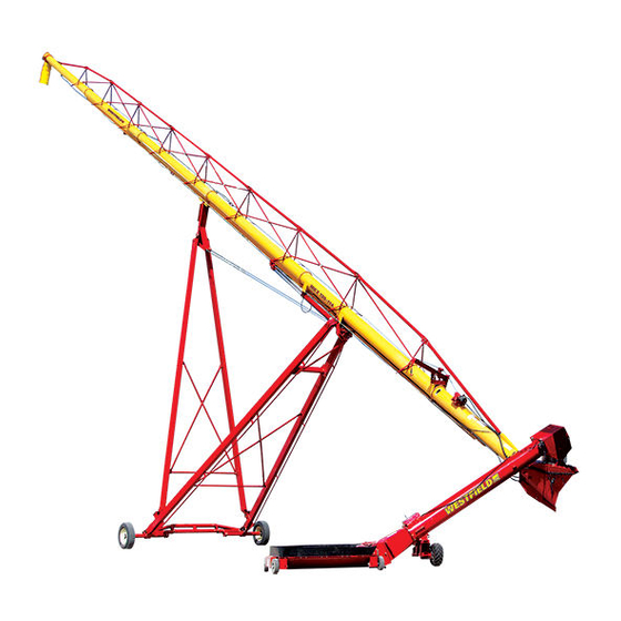
Swing-Away Grain Auger
Portable Grain Auger
Assembly Manual
This manual applies to:
Westfield MKX16, AGI X16, Hutchinson HX16,
Mayrath HX16, Grainmaxx GMX16:
85', 105', 125'
Original Instructions
Read this manual before using product. Failure to
follow instructions and safety precautions can
result in serious injury, death, or property
damage. Keep manual for future reference.
LOOKING FOR PARTS?
Check out our online
Parts Catalog!
Part Number: 30869 R8
Revised: June 2020
Advertisement
Table of Contents

Related Manuals for AGI Westfield MKX16


Summary of Contents for AGI Westfield MKX16
- Page 1 Swing-Away Grain Auger Portable Grain Auger Assembly Manual This manual applies to: Westfield MKX16, AGI X16, Hutchinson HX16, Mayrath HX16, Grainmaxx GMX16: 85', 105', 125' Original Instructions LOOKING FOR PARTS? Check out our online Parts Catalog! Read this manual before using product. Failure to...
- Page 2 New in this Manual The following changes have been made in this revision of the manual: Description Section Added boot flight collar. Section 4.9 – Install the Boot on the Auger Tube on page 38 Added image for truss tube installation. Section 4.15 –...
-
Page 3: Table Of Contents
SWING-AWAY GRAIN AUGER – PORTABLE GRAIN AUGER CONTENTS 1. Introduction ............................5 2. Safety............................... 6 2.1 Safety Alert Symbol and Signal Words..................6 2.2 General Safety ........................... 6 2.3 Rotating Flighting Safety ......................7 2.4 Rotating Parts Safety......................... 7 2.5 Hydraulic Winch Safety ......................7 2.6 Drives and Lockout Safety...................... - Page 4 SWING-AWAY GRAIN AUGER – PORTABLE GRAIN AUGER 4.26.1 Power Swing Components ..................81 4.26.2 Install the Landing Gear ..................81 4.26.3 Install and Connect the Receiver Box ..............84 4.27 Install the Hitch Jack......................88 4.28 Install the Manual Container ....................89 5.
-
Page 5: Introduction
1 1 . . I I n n t t r r o o d d u u c c t t i i o o n n This manual describes how to assemble a AGI Portable Grain Auger. Before assembling, please read this manual. Familiarize yourself with the process and the necessary precautions for efficient and safe assembly. -
Page 6: Safety
• Follow a health and safety program for your worksite. Contact your local occupational health and safety organization for information. • Contact your local representative or AGI if you need assistance or additional information. • Always follow applicable local codes and regulations. -
Page 7: Rotating Flighting Safety
SWING-AWAY GRAIN AUGER – PORTABLE GRAIN AUGER 2. SAFETY 2.3. Rotating Flighting Safety • KEEP AWAY from rotating flighting. • DO NOT remove or modify flighting guards, doors, or covers. Keep in good working order. Have replaced if damaged. • DO NOT operate the auger without all guards, doors, and covers in place. -
Page 8: Pto Driveline Safety
2. SAFETY SWING-AWAY GRAIN AUGER – PORTABLE GRAIN AUGER 2.6.1 PTO Driveline Safety Drive • Keep body, hair, and clothing away from rotating PTO driveline. • Make certain the driveline shields telescope and rotate freely on driveline before attaching. • Make certain the driveline is securely attached at both ends. •... -
Page 9: Hydraulic Power Safety
SWING-AWAY GRAIN AUGER – PORTABLE GRAIN AUGER 2. SAFETY 2.6.2 Hydraulic Power Safety Power Source • Refer to the rules and regulations applicable to the power source operating your hydraulic drive. • Do not connect or disconnect hydraulic lines while system is under pressure. -
Page 10: Tire Safety
2. SAFETY SWING-AWAY GRAIN AUGER – PORTABLE GRAIN AUGER 2.7. Tire Safety Failure to follow proper procedures when mounting a tire on a wheel or rim can produce an explosion that may result in serious injury or death. • DO NOT attempt to mount a tire unless you have the proper equipment and experience to do the job. -
Page 11: Safety Equipment
SWING-AWAY GRAIN AUGER – PORTABLE GRAIN AUGER 2. SAFETY Steel-Toe Boots • Wear steel-toe boots to protect feet from falling debris. Work Gloves • Wear work gloves to protect your hands from sharp and rough edges. Dust Mask • Wear a dust mask to prevent breathing potentially harmful dust. Hearing Protection •... -
Page 12: Decal Installation/Replacement
2. SAFETY SWING-AWAY GRAIN AUGER – PORTABLE GRAIN AUGER 2.10.1 Decal Installation/Replacement 1. Decal area must be clean and dry, with a temperature above 50°F (10°C). 2. Decide on the exact position before you remove the backing paper. 3. Align the decal over the specified area and carefully press the small portion with the exposed sticky backing in place. - Page 13 SWING-AWAY GRAIN AUGER – PORTABLE GRAIN AUGER 2. SAFETY Table 1. Safety Decals Part Number Description 20813 DANGER ROTATING FLIGHTING HAZARD To prevent death or serious injury: • KEEP AWAY from rotating auger flighting. • DO NOT remove or modify auger flighting guards, doors, or covers.
- Page 14 2. SAFETY SWING-AWAY GRAIN AUGER – PORTABLE GRAIN AUGER Table 1 Safety Decals (continued) Part Number Description 17094 DANGER ROTATING FLIGHTING INSIDE To prevent serious injury or death, do not operate auger unless swing- hopper is securely attached to boot. 20816 DANGER ELECTROCUTION HAZARD...
- Page 15 SWING-AWAY GRAIN AUGER – PORTABLE GRAIN AUGER 2. SAFETY Table 1 Safety Decals (continued) Part Number Description 20804 WARNING ENTANGLEMENT HAZARD To prevent serious injury or death: • Keep body, hair, and clothing away from rotating pulleys, belts, chains, and sprockets. •...
- Page 16 2. SAFETY SWING-AWAY GRAIN AUGER – PORTABLE GRAIN AUGER Table 1 Safety Decals (continued) Part Number Description 20811 WARNING UPENDING HAZARD To prevent death or serious injury: • Anchor intake end and/or support discharge end to prevent upending. • Intake end must always have downward weight. Do not release until attached to tow bar or resting on ground.
- Page 17 SWING-AWAY GRAIN AUGER – PORTABLE GRAIN AUGER 2. SAFETY Table 1 Safety Decals (continued) Part Number Description 20807 WARNING To prevent serious injury or death: • Read and understand the manual before assembling, operating, or maintaining the equipment. • Only trained personnel may assemble, operate, or maintain the equipment.
- Page 18 2. SAFETY SWING-AWAY GRAIN AUGER – PORTABLE GRAIN AUGER Table 1 Safety Decals (continued) Part Number Description 20809 WARNING To prevent serious injury or death: • Keep away from rotating cable sheaves and lift cables. • Inspect lift cable periodically; replace if damaged. •...
- Page 19 SWING-AWAY GRAIN AUGER – PORTABLE GRAIN AUGER 2. SAFETY Table 1 Safety Decals (continued) Part Number Description 20806 WARNING HIGH PRESSURE FLUID HAZARD Hydraulic fluid can cause serious injury if it penetrates the skin. If it does, see a doctor immediately.
- Page 20 2. SAFETY SWING-AWAY GRAIN AUGER – PORTABLE GRAIN AUGER Table 1 Safety Decals (continued) Part Number Description 17377 NOTICE To lower equipment, start tractor, then engage hydraulic lever in down position. • This pumps oil to upper chamber of the hydraulic cylinders preventing overfill of tractor reservoir.
- Page 21 SWING-AWAY GRAIN AUGER – PORTABLE GRAIN AUGER 2. SAFETY Table 1 Safety Decals (continued) Part Number Description 21074 NOTICE To prevent damage during auger-to- tractor hookup: • Follow dimensions above for correct auger-to-tractor hookup. • Auger must be on level ground and in full down position when measuring.
-
Page 22: Features
3. FEATURES SWING-AWAY GRAIN AUGER – PORTABLE GRAIN AUGER 3 3 . . F F e e a a t t u u r r e e s s This section covers the main features of the auger. Discharge Spout Hydraulic Cylinders Truss Tower Track... - Page 23 SWING-AWAY GRAIN AUGER – PORTABLE GRAIN AUGER 3. FEATURES Grain Transfer Boot Features Spout Head Service Cover Hitch Angle Adjuster Spout Head Overflow Panel Clean-Out Hatch Spout Head Jack 10 Grain Transfer Boot Auger Tube Lift Valve 11 Speed Reducer Gearbox PTO Driveline Hitch 12 Manual Holder...
- Page 24 3. FEATURES SWING-AWAY GRAIN AUGER – PORTABLE GRAIN AUGER Grain Hopper Features Spout Head Boot Main Auger Swing Arm Power Swing Remote Transmitter Power Swing Drive Wheels Cleanout Hatch Flights and Flight Guarding Intake Hopper Grain Hopper Lifted into Transport Position Winch Chain And Hook Safety Chain And Hook 30869 R8...
- Page 25 SWING-AWAY GRAIN AUGER – PORTABLE GRAIN AUGER 3. FEATURES Auger Tube Hydraulic Lift Cylinders 30869 R8...
-
Page 26: Assembly
Take pictures of shipments prior to or just after unloading if there are any damaged parts. Report missing or damaged parts immediately to ensure that proper credit is received from AGI or your representative, and to ensure that any missing parts can be shipped quickly to avoid holding up the assembly process. -
Page 27: Before You Begin
SWING-AWAY GRAIN AUGER – PORTABLE GRAIN AUGER 4. ASSEMBLY 4.3. Before You Begin Before you assemble the auger: • Familiarize yourself with all the sub-assemblies, components, and hardware that make up the equipment. • Have all parts and components on hand, and arrange them for easy access. •... - Page 28 4. ASSEMBLY SWING-AWAY GRAIN AUGER – PORTABLE GRAIN AUGER Figure 2. 105' and 125’ Logo and Model Decal Locations LOWER MIDDLE TUBE AUGER MODEL DECAL UPPER MIDDLE TUBE BRAND LOGO DECAL 30869 R8...
-
Page 29: Identify And Arrange Auger Tube Sections
SWING-AWAY GRAIN AUGER – PORTABLE GRAIN AUGER 4. ASSEMBLY 4.5. Identify and Arrange Auger Tube Sections 1. Align tube sections on a series of support stands, placing a support stand at the end of each tube. See figures below for correct tube positioning. 2. - Page 30 4. ASSEMBLY SWING-AWAY GRAIN AUGER – PORTABLE GRAIN AUGER Figure 4. 105' Tube Identification and Order LOWER TUBE LOWER MIDDLE TUBE MIDDLE TUBE UPPER MIDDLE TUBE UPPER TUBE Figure 5. 125' Tube Identification and Order LOWER TUBE LOWER MIDDLE TUBE MIDDLE TUBE MIDDLE TUBE UPPER MIDDLE TUBE...
-
Page 31: Connect Auger Tubes
SWING-AWAY GRAIN AUGER – PORTABLE GRAIN AUGER 4. ASSEMBLY 4.6. Connect Auger Tubes Important Always strap tubes to the support stands to prevent the tubes from rolling off the stands. Note Assemble the auger tube starting with the discharge section and working toward the intake section. 1. - Page 32 4. ASSEMBLY SWING-AWAY GRAIN AUGER – PORTABLE GRAIN AUGER Figure 7. Track-to-Flange Tube Section Connection 30869 R8...
-
Page 33: Hydraulic Lift Cylinders
SWING-AWAY GRAIN AUGER – PORTABLE GRAIN AUGER 4. ASSEMBLY 4.7. Hydraulic Lift Cylinders 4.7.1 Install the 85' Hydraulic Lift Cylinders 1. Identify the tube section where the hydraulic lift cylinders install, and note the location of the cylinder mounts. 2. Slide the cylinder rod guide onto the end of the track closest to where the lift cylinders install. Ensure that gussets of ram guide are facing the discharge end. - Page 34 4. ASSEMBLY SWING-AWAY GRAIN AUGER – PORTABLE GRAIN AUGER Figure 8. Installing the Lift Cylinders (85') 30869 R8...
-
Page 35: Install The 105'/125' Hydraulic Lift Cylinders
SWING-AWAY GRAIN AUGER – PORTABLE GRAIN AUGER 4. ASSEMBLY 4.7.2 Install the 105'/125' Hydraulic Lift Cylinders 1. Identify the tube section where the hydraulic lift cylinders install, and note the location of the tube cylinder mounts. 2. Ensure that the tube cylinder mounts are facing down. 3. -
Page 36: Install The Track Shoe And Track Stop
4. ASSEMBLY SWING-AWAY GRAIN AUGER – PORTABLE GRAIN AUGER Table 4 Install the 105'/125' Hydraulic Lift Cylinders (continued) Description Quantity Item 1/2 x 1-3/4” bolt 1/2” locknut Half clamp Figure 9. Installing the Lift Cylinders (105'/125') 4.8. Install the Track Shoe and Track Stop 1. - Page 37 SWING-AWAY GRAIN AUGER – PORTABLE GRAIN AUGER 4. ASSEMBLY Figure 10. Track Stop Positions 125' MODEL 105' MODEL 85' MODEL INTAKE END SPOUT END Table 5. Track Shoe and Track Stop Description Quantity Item Track shoe Track stop 3/4” x 3” GR8 bolts 3/4”...
-
Page 38: Install The Boot On The Auger Tube
4. ASSEMBLY SWING-AWAY GRAIN AUGER – PORTABLE GRAIN AUGER 4.9. Install the Boot on the Auger Tube Note • The boot lower gearbox is sent from the factory filled half way with gear oil (1.7 L [1.8 qt]). Before further assembly, check oil level to make certain the gearbox is half full. Add oil if necessary. Do not use grease. -
Page 39: Assemble The Pto Shield Assembly
SWING-AWAY GRAIN AUGER – PORTABLE GRAIN AUGER 4. ASSEMBLY Figure 12. Install Boot on Auger Tube 4.10. Assemble the PTO Shield Assembly 1. As shown in Figure 13, align the PTO shield front on the PTO shield rear and secure it with three 5/16” x 3/ 4”... -
Page 40: Install The Speed Reducer On The Boot
4. ASSEMBLY SWING-AWAY GRAIN AUGER – PORTABLE GRAIN AUGER Figure 13. Assemble the PTO Shield Assembly 4.11. Install the Speed Reducer on the Boot 1. Lift the speed reducer and carefully slide it over the gearbox and lower flighting shafts and against the face of the boot. - Page 41 SWING-AWAY GRAIN AUGER – PORTABLE GRAIN AUGER 4. ASSEMBLY Table 8. Install the Speed Reducer on the Boot Description Quantity Item Speed reducer Lower gearbox shaft Lower flight shaft PTO driveline strap PTO shield 1/2” x 11-1/2” GR8 bolts 1/2” locknuts Lower gearbox bearing case Lower flight bearing case Lower flight stop...
- Page 42 4. ASSEMBLY SWING-AWAY GRAIN AUGER – PORTABLE GRAIN AUGER Figure 14. Installing the Speed Reducer Figure 15. Install the Shaft Square Keys and Lower Flight Stop 30869 R8...
-
Page 43: Install The Boot Tow Bar
SWING-AWAY GRAIN AUGER – PORTABLE GRAIN AUGER 4. ASSEMBLY 4.12. Install the Boot Tow Bar 1. Insert the tow bar into the boot channel (see Figure 16), and secure the back end loosely with a 3/4” x 6-1/ 2” bolt and 3/4” locknut through the hole in the boot channel. 2. -
Page 44: Install The Discharge Spout
4. ASSEMBLY SWING-AWAY GRAIN AUGER – PORTABLE GRAIN AUGER 4.13. Install the Discharge Spout 1. Align the discharge spout over the opening in the upper tube. 2. Attach the discharge spout with two 5/8” x 3” GR8 bolts and 5/8” locknuts on each side. Table 10. -
Page 45: Install Truss Support Towers And Truss Tubes
SWING-AWAY GRAIN AUGER – PORTABLE GRAIN AUGER 4. ASSEMBLY Figure 18. Setting the Thrust Adjuster 4.15. Install Truss Support Towers and Truss Tubes Due to rigidity of the tubular trussing, do not put an upward bow in the auger. Assemble trussing with main auger tube straight/level and well supported over its length. - Page 46 4. ASSEMBLY SWING-AWAY GRAIN AUGER – PORTABLE GRAIN AUGER Note Single cross-brace tubes are used between the two truss towers closest the ends of the main auger tube, and two cross-brace tubes are required between all other truss tower sets. d.
- Page 47 SWING-AWAY GRAIN AUGER – PORTABLE GRAIN AUGER 4. ASSEMBLY Figure 19. 85' Truss Tower Brackets HIGH HIGH HIGH HIGH 30869 R8...
- Page 48 4. ASSEMBLY SWING-AWAY GRAIN AUGER – PORTABLE GRAIN AUGER Figure 20. 105' Truss Tower Brackets HIGH HIGH HIGH HIGH HIGH HIGH 30869 R8...
- Page 49 SWING-AWAY GRAIN AUGER – PORTABLE GRAIN AUGER 4. ASSEMBLY Figure 21. 125' Truss Tower Brackets HIGH HIGH HIGH HIGH HIGH HIGH HIGH HIGH 30869 R8...
- Page 50 4. ASSEMBLY SWING-AWAY GRAIN AUGER – PORTABLE GRAIN AUGER Figure 22. 85' Truss Tubes 30869 R8...
- Page 51 SWING-AWAY GRAIN AUGER – PORTABLE GRAIN AUGER 4. ASSEMBLY Figure 23. 105' Truss Tubes 30869 R8...
- Page 52 4. ASSEMBLY SWING-AWAY GRAIN AUGER – PORTABLE GRAIN AUGER Figure 24. 125' Truss Tubes 30869 R8...
-
Page 53: Install Truss Cables
SWING-AWAY GRAIN AUGER – PORTABLE GRAIN AUGER 4. ASSEMBLY 4.16. Install Truss Cables Figure 25 on page 55 for details (85' model shown, other models are similar). 1. Thread truss cable through eyebolts and double-back a minimum of 15-1/4" (39 cm) of cable. Secure the cable in place by installing and tightening three 1/2"... - Page 54 4. ASSEMBLY SWING-AWAY GRAIN AUGER – PORTABLE GRAIN AUGER Table 12. Truss Cables Parts Reference Description Item 3/4'' x 11-1/2'' Eyebolt 3/4” Locknut 1/2” cable Clamp 1/2” x 68’ x 2 Cable 1/2” x 90’ x 2 Cable 1/2” x 110’ x 2 Cable Lower Tube Cable Return Bracket 1/2”...
- Page 55 SWING-AWAY GRAIN AUGER – PORTABLE GRAIN AUGER 4. ASSEMBLY Figure 25. Truss Cables 30869 R8...
-
Page 56: Assemble The Lower Frame
4. ASSEMBLY SWING-AWAY GRAIN AUGER – PORTABLE GRAIN AUGER 4.17. Assemble the Lower Frame 1. Fasten the lower reach arms to the axle with four 3/4" x 2" bolts and locknuts on each side. Tighten securely. Note Insert a punch tool (P) in the middle hole to help align the four bolt holes. 2. - Page 57 SWING-AWAY GRAIN AUGER – PORTABLE GRAIN AUGER 4. ASSEMBLY 3. Install the stabilizer braces on either side of the short cross member with a single 5/8” x 2” bolt and locknut per side. Leave loose until the other ends of the stabilizer braces are connected in Section 4.18 –...
-
Page 58: Connect The Auger Tube To The Frame
4. ASSEMBLY SWING-AWAY GRAIN AUGER – PORTABLE GRAIN AUGER 4.18. Connect the Auger Tube to the Frame 1. Raise the discharge end of auger (e.g. with a front end loader and a strong sling, or with a chain or block and tackle). - Page 59 SWING-AWAY GRAIN AUGER – PORTABLE GRAIN AUGER 4. ASSEMBLY Table 14. Parts Required to Connect the Auger Tube to the Frame Item Description Quantity Stabilizer Bracket Tube Frame Pin 7/16” x 3-1/2” GR5 Bolt 7/16” Locknut Axle Frame Pin 1/2” x 1-1/2” GR8 Bolt 1/2”x1-3/4”...
- Page 60 4. ASSEMBLY SWING-AWAY GRAIN AUGER – PORTABLE GRAIN AUGER Figure 27. Connecting the Auger Tube to the Frame 30869 R8...
-
Page 61: Install Lift Cylinder Cables To The Lift Assist
SWING-AWAY GRAIN AUGER – PORTABLE GRAIN AUGER 4. ASSEMBLY 4.19. Install Lift Cylinder Cables to the Lift Assist Track shoe must rest against track stop when adjusting cable. If this isn’t done, the auger can raise higher than designed to lift, resulting in damage to auger and possible injury to personnel. - Page 62 4. ASSEMBLY SWING-AWAY GRAIN AUGER – PORTABLE GRAIN AUGER Figure 28. Connecting the Lift Cylinder Cables 85’ MODEL 105/125’ MODELS 30869 R8...
-
Page 63: Connect Hydraulic Hoses And Ball Valve
SWING-AWAY GRAIN AUGER – PORTABLE GRAIN AUGER 4. ASSEMBLY 4.20. Connect Hydraulic Hoses and Ball Valve Table 15. Hydraulic Hoses Hose Description Usage Hydraulic Pressure 85 HOSE, 1/2” x 228” 85 HOSE, 1/2” x 396” Hydraulic Return Hydraulic Pressure 105 HOSE, 1/2” x 302” Hydraulic Return 105 HOSE, 1/2”... - Page 64 4. ASSEMBLY SWING-AWAY GRAIN AUGER – PORTABLE GRAIN AUGER 7. Tighten hydraulic hose catch snugly enough to hold hoses in place. (See Figure 33). 8. Run both hoses straight down the side of the auger to the ball valve location on the boot, fastening the hoses at each available hose catch.
- Page 65 SWING-AWAY GRAIN AUGER – PORTABLE GRAIN AUGER 4. ASSEMBLY Table 16. Lift Cylinder Hydraulic Hoses and Fittings (85') Description Number Cap End of Cylinders Lower End (intake) Fluid Return Hose Pressure Hose Cylinder 1 Cylinder 3 Cylinder 2 Rod End of Cylinders Upper End (discharge) Figure 30.
- Page 66 4. ASSEMBLY SWING-AWAY GRAIN AUGER – PORTABLE GRAIN AUGER Table 17. Lift Cylinder Hydraulic Hoses and Fittings (105'/125') Description Number Cap End of Cylinders Lower End (intake) Pressure Hose Fluid Return Hose Cylinder 1 Cylinder 2 Upper End (discharge) Rod End of Cylinders 30869 R8...
- Page 67 SWING-AWAY GRAIN AUGER – PORTABLE GRAIN AUGER 4. ASSEMBLY Figure 31. Hydraulic Diagram (85') 30869 R8...
- Page 68 4. ASSEMBLY SWING-AWAY GRAIN AUGER – PORTABLE GRAIN AUGER Table 18. Hydraulic Diagram (85') Description Number Discharge Intake Cylinder 1 Cylinder 2 Cylinder 3 3/8” Elbow Fitting 3/8” Tee Fitting Short Hydraulic Hose, 32” Short Hydraulic Hose, 16” Long Hydraulic Lift Hose, Pressure (with ball valve and 3/8”...
- Page 69 SWING-AWAY GRAIN AUGER – PORTABLE GRAIN AUGER 4. ASSEMBLY Figure 32. Hydraulic Diagram (105'/125') 30869 R8...
- Page 70 4. ASSEMBLY SWING-AWAY GRAIN AUGER – PORTABLE GRAIN AUGER Table 19. Hydraulic Diagram (105'/125') Description Number Cylinder 1 Cylinder 2 1/2” Elbow Fitting 1/2” Tee Fitting Short Hydraulic Hose, 48” Short Hydraulic Hose, 36” Long Hydraulic Lift Hose, Pressure (with ball valve and 3/8”...
-
Page 71: Connect The Pto Driveline
SWING-AWAY GRAIN AUGER – PORTABLE GRAIN AUGER 4. ASSEMBLY Figure 34. Installing the Ball Valve on the Boot 1/4” X 3/4” BOLTS [9900800] AND 1/4” LOCKNUTS [28449] Table 21. Installing the Ball Valve on the Boot Description Number 1/4” x 3/4” Bolts 1/4”... - Page 72 4. ASSEMBLY SWING-AWAY GRAIN AUGER – PORTABLE GRAIN AUGER Figure 35. Connecting the Stub Shaft to the PTO Driveline 3. Insert the splined end of the PTO stub shaft into the “forward” speed reducer gear box position. 4. Slide the PTO transport saddle through the support strap on the boot and rest the PTO driveline in it. Figure 36.
-
Page 73: Connect The Intake Hopper To The Swing Tube
SWING-AWAY GRAIN AUGER – PORTABLE GRAIN AUGER 4. ASSEMBLY Table 22. PTO Parts and Installation Description Item Forward Reverse 4.22. Connect the Intake Hopper to the Swing Tube Lockout the lifting apparatus before working around or under the raised components. Failure to do so may cause serious personal injury. - Page 74 4. ASSEMBLY SWING-AWAY GRAIN AUGER – PORTABLE GRAIN AUGER 4. Secure the U-joint to the swing flight with a 3/8” set screw, a 5/16” x 2-3/4” bolt, and a locknut. 5. Slide the transition flight shaft into the U-joint. Figure 37. Secure Bushing Support and Connect Transition Flight 6.
- Page 75 SWING-AWAY GRAIN AUGER – PORTABLE GRAIN AUGER 4. ASSEMBLY Figure 38. Connecting the Transition to the Intake Hopper 15,16 15,16 9. Attach the six solid wheels to the four hopper corners with the axle pins and hairpins. There are three height settings (Figure 39)that can be used according to preference.
-
Page 76: Connect The Spout Head To The Grain Transfer Boot
4. ASSEMBLY SWING-AWAY GRAIN AUGER – PORTABLE GRAIN AUGER 4.23. Connect the Spout Head to the Grain Transfer Boot Table 24. Parts Required to Connect the Spout Head to the Boot Description Quantity Item Service Cover Spring Clasps Gearbox Coupler (2A Top, 2B Bottom) 3/8”... -
Page 77: Install The Hopper Lift Arm
SWING-AWAY GRAIN AUGER – PORTABLE GRAIN AUGER 4. ASSEMBLY Figure 40. Connecting the Spout Head to the Boot WELD BETWEEN SHAFT SPLINES GAP BETWEEN SPLINES 4.24. Install the Hopper Lift Arm 1. Determine which side of the auger the hopper will be operating on. Note Feed side of hopper must face the main auger when in transport. -
Page 78: Install The Hydraulic Winch
4. ASSEMBLY SWING-AWAY GRAIN AUGER – PORTABLE GRAIN AUGER Figure 41. Installing the Lift Arm 4.25. Install the Hydraulic Winch 1. Position the hydraulic winch on the winch mounting plate, and secure it using three 3/8” washers and three 3/8” locknuts as shown in Figure 2. - Page 79 SWING-AWAY GRAIN AUGER – PORTABLE GRAIN AUGER 4. ASSEMBLY Figure 42. Installing the Hydraulic Winch 5/16” X 1” BOLTS [17125] AND LOCKNUTS [19980] 3/8” LOCK NUTS [17402] HYDRAULIC WINCH LIFT ARM PULLEY GUIDE 3/8” FLAT WASHERS [17392] WINCH MOUNTING POSITION FOR MANUAL WINCH PLATE Figure 43.
- Page 80 4. ASSEMBLY SWING-AWAY GRAIN AUGER – PORTABLE GRAIN AUGER Figure 44. Installing the Hydraulic Winch Hose Table 25. Installing the Hydraulic Winch Hose Description Item Steel Elbow 90.1 / 2FNPSMX3 / 8MNPT 1/2” x 226” Hydraulic Hose Pioneer Coupler 30869 R8...
-
Page 81: Electric Power Swing Assembly
SWING-AWAY GRAIN AUGER – PORTABLE GRAIN AUGER 4. ASSEMBLY 4.26. Electric Power Swing Assembly 4.26.1 Power Swing Components Figure 45. Electric Power Swing Components Table 26. Electric Power Swing Components Part Description Item Manual Jack Attach Bracket Right-Side Attach Bracket Landing Gear Assembly (Electric) Landing Gear Wheels Receiver Top-Clamp Assembly... - Page 82 4. ASSEMBLY SWING-AWAY GRAIN AUGER – PORTABLE GRAIN AUGER 2. Fasten the jack attach bracket to the swing tube using four 7/16" x 1-1/4" bolts and locknuts. 3. Slide the upper manual jack attachment onto the manual jack attach pin, and secure using a lynch pin. 4.
- Page 83 SWING-AWAY GRAIN AUGER – PORTABLE GRAIN AUGER 4. ASSEMBLY Figure 46. Attach the Landing Gear to the Tube 30869 R8...
-
Page 84: Install And Connect The Receiver Box
4. ASSEMBLY SWING-AWAY GRAIN AUGER – PORTABLE GRAIN AUGER 4.26.3 Install and Connect the Receiver Box 1. Position the receiver top clamp assembly approximately 24" from the transition attach plate and secure using eight 7/16” x 1-1/4” bolts and locknuts. Tighten both sides securely. 2. - Page 85 SWING-AWAY GRAIN AUGER – PORTABLE GRAIN AUGER 4. ASSEMBLY b. Place the wire on, and then replace the nut. c. Tighten securely. d. Repeat the same steps for the negative wire and terminal. 7. Route the long electrical cable up the swing tube and secure it using an insulated clamp, a 1/4” x 3/4” bolt, and a 1/4”...
- Page 86 4. ASSEMBLY SWING-AWAY GRAIN AUGER – PORTABLE GRAIN AUGER Figure 48. Connecting the Receiver Box QUICK CONNECT POSITIVE WIRE WITH RED BOOT CONNECTS TO POSITIVE MOTOR TERMINAL. NEGATIVE WIRE CONNECTS TO NEGATIVE MOTOR TERMINAL. 30869 R8...
- Page 87 SWING-AWAY GRAIN AUGER – PORTABLE GRAIN AUGER 4. ASSEMBLY Table 29. Connecting the Receiver Box to the Motors and Battery Part Description Item 5/8” x 1/2” Insulated Clamp 1/4” x 3/4” Bolt 1/4” Locknut Quick Connect Positive wire Negative wire Long Electrical Cable 9, 13 Short Electrical Cable...
-
Page 88: Install The Hitch Jack
4. ASSEMBLY SWING-AWAY GRAIN AUGER – PORTABLE GRAIN AUGER Figure 49. Power Swing Wiring Diagram 4.27. Install the Hitch Jack The jack is attached to the auger with a pin at the pivot point. To install: 1. Elevate the auger boot (intake end) approximately 2’ (5.08 cm) with a front- end loader and sling, and install the jack in a vertical position. -
Page 89: Install The Manual Container
SWING-AWAY GRAIN AUGER – PORTABLE GRAIN AUGER 4. ASSEMBLY 4.28. Install the Manual Container Mount the plastic manual holder directly to the boot (as shown below) using three self-tapping screws. Figure 50. Installing the Plastic Manual Container 30869 R8... -
Page 90: Specifications
5. SPECIFICATIONS SWING-AWAY GRAIN AUGER – PORTABLE GRAIN AUGER 5 5 . . S S p p e e c c i i f f i i c c a a t t i i o o n n s s Specification 16–85 16–105... -
Page 91: Appendix
Tighten all bolts to the torque specified, unless otherwise noted. Check tightness periodically, using Table 30 as a guide. Replace the hardware with the same strength bolt, contact AGI if you are unsure. Table 30. Recommended Bolt Torque Recommended Torque (ft-lb) Threads... - Page 92 P.O. Box 39 Rosenort, Manitoba, R0G 1W0 Canada Phone: (866) 467-7207 (Canada & USA) or (204) 746–2396 Fax: (866) 768-4852 Website: www.grainaugers.com Email: sales@grainaugers.com ©Ag Growth International Inc. 2020 Printed in Canada If you have any comments or questions on this manual, or find an error, email us at comments@aggrowth.com. Please include the part number listed on the cover page in your message.
Need help?
Do you have a question about the Westfield MKX16 and is the answer not in the manual?
Questions and answers