Table of Contents
Advertisement
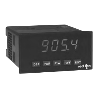
MPAX PERSONALITY MODULE SELECTOR GUIDE FOR LPAX
Our large displays have various input options, determined by the installation of a MPAX personality module. These MPAX
modules are based on standard PAX panel meters, and use the same data sheet as the PAX meter for specifications and wiring.
About the MPAX Input Modules
The MPAX Module serves as the input to the LPAX Display. There are several different modules to cover a variety of inputs. The
MPAX module provides input scaling which allows the LPAX to display most any engineering unit. Once the MPAX is inserted into
the LPAX, the unit has the same functions and capabilities of our PAX Series Intelligent Panel Meters. A full set of PAX
programming instructions will be included with the MPAX Module.
Note: The MPAX provides the operating power for the LPAX, therefore you must select either the AC or DC MPAX corre sponding
with your application and available power.
Selecting Your Display Components
To build a complete display unit, you will need an LPAX and an MPAX Input Module. The LPAX is only a display and will not
operate without an MPAX Module. Please use the following chart to identify the appropriate MPAX Module (including supply
power) and LPAX Display that will satisfy your application.
MPAX Modules for LPAX5 (Analog units)
SIGNAL TYPE
DC Voltage 200 m V, 2 V, 20 V, 300 V
Universal DC Inpu ts
DC Current 200 µA, 2 mA, 20 mA, 200 mA, 2 Amp
Resi stance 100 ohm, 1000 ohm, 10
Process Inpu ts
0-20 mA or 0-10 V
Thermocouples -T , E, J, K, R, S, B, N, C,
Temperature Inpu ts
or Custom Scaling RTDs - 100 ohm Pt (platinum) 385/392,
120 ohm Nickel 672, or 10 ohm Copper 427
Strain Gage/Load Cell
24 mV or 240 mV
True RMS AC
AC Voltage 200 m V, 2 V, 20 V, 300 V
Voltage/Current
AC Current 200 uA, 2 mA, 20 mA, 200 mA, 5 Amp
MPAX Modules for LPAX6 (Digital units)
SIGNAL TYPE
Count/Rate/Serial Slave
Count
Rate
Clock/ Timer
Time
r
MPAX Modules for LPAXDA (Dual Analog Unit)
SIGNAL TYPE
Dual Process Inputs
0-20 mA or
INPUT RANGES
DC
*
MPAX MODULES
85-250 VAC
11 to 36 VDC / 24 VAC
†
MPAXI000
MPAXI010
MPAXC000
MPAXC010
MPAXR000
MPAXR010
††
MPAXCK0 0
MPAXCK1 0
††
MPAXTM00
MPAXTM10
INPUT RANGES
0-10 VDC
MPAXD000
K ohm
MPAXP000
MPAXT000
MPAXS000
MPAXH000
LPAX
DISPLAYS
SETPOINT
†
LPAX0600
YES
LPAX0600
YES
LPAX0600
YES
††
**
LPAXCK0 0
YES
††
**
LPAXCK0 0
YES
85-250 VAC
MPAXDP00
*
MPAX MODULES
85-250 VAC
11 to 36 VDC/ 24 VAC
MPAXD010
MPAXP010
MPAXT010
MPAXS010
N/A
OPTIONAL PLUG-IN CARD COMPATIBILITY
COMMS
ANALOG
YES
YES
-
-
YES
YES
*
MPAX MODULES
11 to 36 VDC/ 24 VAC
MPAXDP10
LPAX DISPLAYS
LPAX0500
LPAX0500
LPAX0500
LPAX0500
LPAX0500
REAL-TIME
CLOCK
-
-
-
-
-
-
YES
-
-
LPAX DISPLAY
LPAXDA00
Advertisement
Table of Contents

Related Manuals for red lion PAXD Series


Summarization of Contents
MPAX Input Modules Overview
About the MPAX Input Modules
Explains the MPAX module's role as input to the LPAX display and its capabilities.
Selecting Your Display Components
Guides the user in selecting the appropriate MPAX module and LPAX display for a complete unit.
PAX Series Panel Meters
General Description
Details features and performance capabilities of PAX Analog Panel Meters for industrial applications.
Safety Summary
Provides safety regulations, local codes, and instructions to ensure personal safety and prevent equipment damage.
Dimensions
Provides physical dimensions and panel cutout information for the meter in inches and millimeters.
Ordering Information
Meter Part Numbers
Explains the structure of meter part numbers and provides a diagram for creating valid part numbers.
Option Card and Accessories Part Numbers
Lists part numbers for optional plug-in cards and accessories, detailing their models and descriptions.
General Meter Specifications
Display, Power, and Annunciators
Details display type, power requirements, annunciator functions, and keypad layout.
Update Rates and Input Capabilities
Covers update rates, input capabilities, excitation power, and noise rejection specifications.
Totalizer, Customization, and Environment
Details totalizer, custom linearization, memory, and environmental conditions.
Certifications, Connections, and Construction
Lists certifications, connection details, construction, and weight specifications.
PAXD Universal DC Input Module
PAXD Specifications
Details input ranges, accuracy, impedance, overload, and resolution for PAXD Universal DC Input.
Excitation Power
Details excitation power specifications for transmitters, reference voltage, and reference current.
PAXP Process Input Module
PAXP Specifications
Details input ranges, accuracy, impedance, overload, and resolution for PAXP Process Input.
Excitation Power
Details transmitter power and excitation specifications for the PAXP Process Input.
PAXH AC True RMS Module
PAXH Specifications
Details input ranges, accuracy, impedance, overload, and resolution for PAXH AC True RMS.
PAXS Strain Gage Input Module
PAXS Specifications
Details input ranges, accuracy, impedance, and overload for PAXS Strain Gage/Bridge Input.
Connection Types and Bridge Excitation
Specifies connection types and jumper selectable bridge excitation options for PAXS.
PAXT Thermocouple and RTD Input Module
PAXT Specifications
Details thermocouple and RTD input ranges, accuracies, standards, and wire color codes.
Thermocouple and RTD Input Details
Details specifications for thermocouple and RTD inputs, including impedance and excitation.
Custom Range
Describes custom range capabilities for PAXT, including data points and input range.
Accessories
Units Label Kit and Current Shunts
Describes the Units Label Kit and External Current Shunts (APSCM) accessories.
Optional Plug-In Output Cards
Adding Option Cards
Explains how to add optional plug-in cards to the PAX and MPAX series meters.
Communication Cards (PAXCDC)
Details various communication card options (RS485, RS232, DeviceNet, Modbus, Profibus-DP).
Programming Software (Crimson)
Describes the Crimson® software for configuring PAX meters via PC, requiring a serial plug-in card.
Setpoint Cards (PAXCDS)
Details the four available setpoint alarm output plug-in cards: Dual Relay, Quad Relay, Sinking, Sourcing.
Analog Output Cards (PAXCDL)
Describes the Linear DC Output card for retransmitted analog output.
Installing the Meter
Installation and Environment
Provides instructions for meter mounting, panel cutout, and environmental considerations.
Setting the Jumpers
Input Range and Excitation Jumpers
Explains jumpers for input range selection and excitation output selection.
User Input Logic, PAXD, and PAXH Jumpers
Details jumpers for user input logic, PAXD ranges, and PAXH signal/couple selection.
Jumper Selections by Model
PAXP Jumper Selection
Illustrates jumper selections for PAXP regarding User Input Logic.
PAXH Jumper Selection
Details jumper selections for PAXH: Input Range, Signal, and Couple Jumper.
PAXS Jumper Selection
Illustrates jumper selections for PAXS regarding Bridge Excitation and Input Range.
3.0 Wiring the Meter
Wiring Overview and EMC Guidelines
Provides general wiring instructions and EMC guidelines for meter installation.
Power Wiring
Illustrates the wiring connections for AC power and DC power terminals on the meter.
3.2 Input Signal Wiring
PAXD Input Signal Wiring
Shows input signal wiring diagrams for PAXD for Voltage, Current, Resistance, and Potentiometer inputs.
PAXP Input Signal Wiring
Shows input signal wiring diagrams for PAXP for Voltage, Current inputs.
Signal Wiring by Model
PAXH Input Signal Wiring
Shows input signal wiring diagrams for PAXH for Voltage, Current (Amps and Milliamps) inputs.
PAXS Input Signal Wiring
Shows input signal wiring diagrams for PAXS for 2-Wire Single Ended, 4-Wire Bridge, and 6-Wire Bridge inputs.
PAXT Input Signal Wiring
Shows input signal wiring diagrams for PAXT for Thermocouple, 3-Wire RTD, and 2-Wire RTD inputs.
PAXS Compensation and Resistors
Explains deadload compensation and bridge completion resistors for PAXS.
3.3 User Input Wiring
Sinking and Sourcing Logic
Explains sinking and sourcing logic for user inputs, including PAXH-specific details.
Front Panel Controls and Programming Overview
Display Mode and Programming Mode Operation
Explains operation of keys in Display Mode and Programming Mode.
User Input and Function Key Functions
Details programmable user inputs and function keys, including programming mode lock-out.
5.0 Programming the Meter
Programming Modes and Tips
Describes Display Mode, Full/Quick Programming Modes, tips, and factory settings.
Step-by-Step Programming Instructions
Provides detailed instructions for entering and navigating programming mode, modules, and parameters.
5.1 Module 1 - Signal Input Parameters
PAX and PAXT Parameter Menus
Displays parameter menu structures for PAX and PAXT modules.
Input Range and Type Selections
Details input range/type selections for PAXS, PAXD, PAXT, and PAXH, including coupling.
Temperature Scale and Display Decimal Point
Covers PAXT temperature scale selection and display decimal point settings.
Module 1 Parameter Details
Rounding, Scaling Points, and Style
Explains display rounding, scaling points (linear/nonlinear), and scaling styles.
PAXT Specific Parameters
Details PAXT temperature offset, filter settings, band, ice point slope.
Scaling Point Value Entry
Provides instructions for entering input and display values for scaling points.
5.2 Module 2 - User Input and Function Key Parameters
User Inputs and Function Keys Overview
Explains programmable user inputs and function keys, and their basic functions.
Specific Functions: Zero Display, Relative/Absolute, Lock-out
Details functions like Zero (Tare) Display, Relative/Absolute Display, and Programming Mode Lock-out.
User Input and Function Key Operations
Display and Function Control Operations
Covers operations like Hold Display, Hold All Functions, Synchronize Meter Reading.
Totalizer and Min/Max Value Operations
Details operations for Totalizer (Store Batch, Select, Reset) and Min/Max values.
Display Intensity Level Adjustment
Explains how to change the display intensity level using user inputs or function keys.
5.3 Module 3 - Display and Program Lock-Out Parameters
Setpoint Selections and Print Request
Covers setpoint selections for alarms and the print request function.
Display and Program Lock-Out Settings
Details lock-out settings for displays (Max, Min, Total) and programming modes.
Setpoint Access and Security Code
Covers setpoint access levels and the programming mode security code.
Programming Mode Access
Details how programming mode access is affected by security code and user input.
5.4 Module 4 - Secondary Function Parameters
Capture Delay, Update Rate, and Backlight
Details max/min capture delay times, display update rate, and units label backlight.
Display Offset and Auto-Zero Tracking
Covers display offset value and auto-zero tracking/band parameters for PAXS.
PAXT Ice Point Compensation
Explains the PAXT Ice Point Compensation parameter.
5.5 Module 5 - Totalizer Parameters
Totalizer Decimal Point and Time Base
Details totalizer decimal point selection and time base settings.
Totalizer Scale Factor and Low Cut Value
Covers totalizer scale factor, low cut value, and power-up reset parameters.
Totalizer Operations and Calculations
Explains totalizer high order display, batching, time base usage, and scale factor calculations.
5.6 Module 6 - Setpoint (Alarm) Parameters
Setpoint Selection and Action
Covers setpoint selection, action, and reset parameters for alarms.
5.7 Module 7 - Serial Communications Parameters
Serial Communication Settings
Details baud rate, data bits, parity bit, meter address, and printing options.
5.8 Module 8 - Analog Output Parameters
Analog Output Configuration
Covers analog output type, assignment, low/high scale values, update time, and burn-out action.
5.9 Module 9 - Factory Service Operations
Display Intensity and Factory Defaults
Details display intensity adjustment and restoring factory defaults.
Meter Calibration Overview
Provides general information on meter calibration procedures and requirements.
Input Calibration by Model
Details input calibration procedures for PAXP, PAXD, and PAXH models.
Calibration Procedures
Model-Specific Input Calibration
Details calibration for PAXH AC Offset, PAXS, PAXT (RTD, Thermocouple), and Ice Point.
RTD and Analog Output Card Calibration
Provides calibration steps for PAXT RTD ranges and the Analog Output Card.
Troubleshooting
Common Problems and Remedies
Lists common meter problems like no display, lock-outs, incorrect values, and their solutions.
Parameter Value Chart
Provides a chart listing parameters, factory settings, and user settings for meter configuration.
LPAX Display Overview
LPAX General Description and Safety
Details the LPAX display's versatility, safety summary, and specifications.
LPAX Specifications and Dimensions
Lists LPAX display specifications including power, input, certifications, and physical dimensions.
MPAX Module and LPAX Display Integration
MPAX Module Environment, Mounting, and Installation
Details environmental, mounting, installation, connections, construction, and weight of MPAX modules.
MPAX Input Modules and Component Selection
Explains MPAX input modules and guides selection of MPAX/LPAX display components.
Optional Plug-in Cards and Accessories
Lists and describes optional plug-in cards (Communication, Setpoint, Analog) and accessories.
1.0 Assembling the Display
Module and Option Card Installation
Provides instructions for installing option cards and the MPAX module into the LPAX case.
Label Application and Module Removal
Covers applying labels and the procedure for removing the MPAX module.
2.0 Installing the LPAX Display
LPAX Display Panel Mounting
Provides instructions for mounting the LPAX display into a panel, including gasket use.
LPAX Environment and Cleaning
Details installation location considerations and cleaning instructions for the LPAX display bezel.
3.0 Wiring and Programming the Display
Wiring and Programming Overview
States that LPAX/MPAX share PAX functions and refers to PAX info for wiring and programming.
Ordering Information Summary
Lists model numbers, descriptions, and part numbers for LPAX, MPAX modules, and accessories.
Need help?
Do you have a question about the PAXD Series and is the answer not in the manual?
Questions and answers