Advertisement
Table of Contents
Tel +1 (717) 767-6511
Fax +1 (717) 764-0839
www.redlion.net
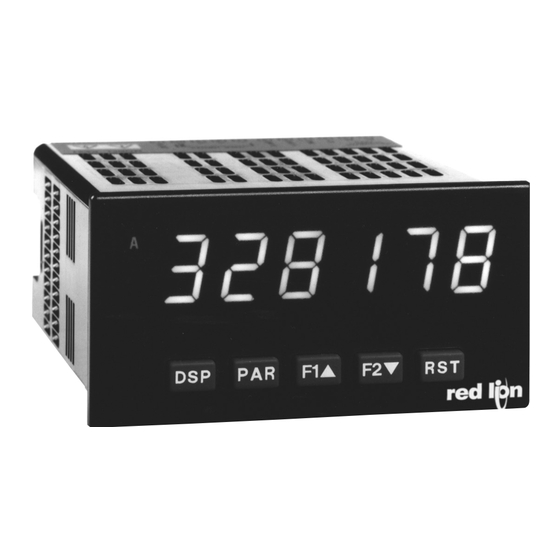
MODEL PAX - 1/8 DIN DIGITAL INPUT PANEL METERS
U L
C
US LISTED
R
IND. CONT. EQ.
51EB
GENERAL DESCRIPTION
The PAX Digital Input Panel Meters offer many features and performance
capabilities to suit a wide range of industrial applications. Available in three
different models, PAXC Counter/Dual Counter, PAXR Rate Meter and the PAXI
which offers both counting and rate in the same package. Refer to pages 4 - 5 for
the details on the specific models. The PAXC and PAXR offer only the Setpoint
Option, while the PAXI is the fully featured version offering all the capabilities
as outlined in this bulletin as well as a slave display feature. The optional plug-in
output cards allow the opportunity to configure the meter for present applications,
while providing easy upgrades for future needs.
The meters employ a bright 0.56" LED display. The meters are available with
a red sunlight readable or standard green LED display. The intensity of the
display can be adjusted from dark room applications up to sunlight readable,
making it ideal for viewing in bright light applications.
The meters accept digital inputs from a variety of sources including switch
contacts, outputs from CMOS or TTL circuits, magnetic pickups and all
standard RLC sensors. The meter can accept directional, uni-directional or
Quadrature signals simultaneously. The maximum input signal varies up to 34
KHz depending on the count mode and function configurations programmed.
Each input signal can be independently scaled to various process values.
The Rate Meters provide a MAX and MIN reading memory with programmable
capture time. The capture time is used to prevent detection of false max or min
readings which may occur during start-up or unusual process events.
Optional digital output plug-in cards provide the meter with up to four
setpoint outputs. The cards are available as dual relay, quad relay, quad sinking
transistor, quad sourcing transistor/SSR drive, or dual triac/dual SSR drive
outputs. The setpoint alarms can be configured to suit a variety of control and
alarm requirements.
Communication and Bus Capabilities are also available as option cards for
the PAXI only. These include RS232, RS485, Modbus, DeviceNet, and
Profibus-DP. Readout values and setpoint alarm values can be controlled
DIMENSIONS In inches (mm)
A
8. 8 . 8 . 8 . 8 . 8
B
C
SP1
SP2
SP3
SP4
DSP
PAR
F1
F2
RST
3.80
(96.5)
Note: Recommended minimum clearance (behind the panel) for
mounting clip installation is 2.1" (53.4) H x 5" (127) W.
1.95
(49.5)
.10
(2.5)
COUNT, DUAL COUNTER, RATE AND SLAVE DISPLAY
0.56" RED SUNLIGHT READABLE DISPLAY
VARIABLE INTENSITY DISPLAY
10 POINT SCALING FOR NON-LINEAR PROCESSES (PAXI)
FOUR SETPOINT ALARM OUTPUTS (W/Option Card)
RETRANSMITTED ANALOG OUTPUT (W/Option Card) (PAXI)
COMMUNICATION AND BUS CAPABILITIES (W/Option Card) (PAXI)
BUS CAPABILITIES; DEVICENET, MODBUS, AND PROFIBUS-DP
CRIMSON
PROGRAMMING SOFTWARE (PAXI)
®
ETHERNET(W/ External Gateway) (PAXI)
NEMA 4X/IP65 SEALED FRONT BEZEL
through the bus. Additionally, the meters have a feature that allows a remote
computer to directly control the outputs of the meter. With an RS232 or RS485
card installed, it is possible to configure the meter using Red Lion's Crimson
software. The configuration data can be saved to a file for later recall.
A linear DC output signal is available as an optional Plug-in card for the PAXI
only. The card provides either 20 mA or 10 V signals. The output can be scaled
independent of the input range and can track any of the counter or rate displays.
Once the meters have been initially configured, the parameter list may be
locked out from further modification in its entirety or only the setpoint values
can be made accessible.
The meters have been specifically designed for harsh industrial environments.
With NEMA 4X/IP65 sealed bezel and extensive testing of noise effects to CE
requirements, the meter provides a tough yet reliable application solution.
SAFETY SUMMARY
All safety related regulations, local codes and instructions that appear in this
literature or on equipment must be observed to ensure personal safety and to
prevent damage to either the instrument or equipment connected to it. If
equipment is used in a manner not specified by the manufacturer, the protection
provided by the equipment may be impaired.
Do not use this meter to directly command motors, valves, or other actuators
not equipped with safeguards. To do so can be potentially harmful to persons or
equipment in the event of a fault to the meter.
CAUTION: Risk of Danger.
Read complete instructions prior to
installation and operation of the unit.
1.75
(44.5)
4.10
(104.1)
1
Bulletin No. PAXICR-D
Drawing No. LP0896
Released 10/14
CAUTION: Risk of electric shock.
12
16
20
13
17
21
14
18
22
15
19
23
24
25
1
2
3
4
5
6
7
8
9
10
11
3.60 (91.4)
1.75
(44.5)
Advertisement
Table of Contents

Related Manuals for red lion PAX


Summary of Contents for red lion PAX
- Page 1 With an RS232 or RS485 The PAX Digital Input Panel Meters offer many features and performance card installed, it is possible to configure the meter using Red Lion’s Crimson capabilities to suit a wide range of industrial applications. Available in three software.
-
Page 2: Table Of Contents
ICM80000 * This card is not suitable for use in older PAX models. For proper installation, a case knock-out feature must be present on the top surface of the PAX case. This feature began to be introduced to the standard PAX units in July of 2014 (2614). -
Page 3: General Meter Specifications
eneral eTer peCifiCaTiOns 1. DISPLAY: 6 digit, 0.56" (14.2 mm) red sunlight readable or standard green 8. CERTIFICATIONS AND COMPLIANCES: CE Approved 2. POWER: EN 61326-1 Immunity to Industrial Locations AC Versions: Emission CISPR 11 Class A AC Power: 85 to 250 VAC, 50/60 Hz, 18 VA Safety requirements for electrical equipment for measurement, control, and Isolation: 2300 Vrms for 1 min. - Page 4 paXC - 1/8 din C Odel OunTer 6-DIGIT LED DISPLAY (Alternating 8 digits for counting) DUAL COUNT QUAD INPUTS UP TO 3 COUNT DISPLAYS SETPOINT ALARM OUTPUTS (W/Plug-in card) PAXC SPECIFICATIONS ANNUNCIATORS: MAXIMUM SIGNAL FREQUENCIES: A - Counter A To determine the maximum frequency for the input(s), first answer the B - Counter B questions with a yes (Y) or no (N).
-
Page 5: Crimson Programming Software
paXi - 1/8 din C Odel OunTer eTer COUNT, RATE AND SLAVE DISPLAY 6-DIGIT 0.56" RED SUNLIGHT READABLE DISPLAY VARIABLE INTENSITY DISPLAY 10 POINT SCALING (FOR NON-LINEAR PROCESSES) FOUR SETPOINT ALARM OUTPUTS (W/OPTION CARD) RETRANSMITTED ANALOG OUTPUT (W/OPTION CARD) ... -
Page 6: Installing Plug-In Cards
Adding Option Cards Contact Rating: The PAX and MPAX series meters can be fitted with up to three optional plug- One Relay Energized: 3 amps @ 250 VAC or 30 VDC (resistive load). in cards. The details for each plug-in card can be reviewed in the specification Total current with all four relays energized not to exceed 4 amps section below. - Page 7 The meter’s program can then be saved in a PC file for future use. A PAX serial plug-in card or PAX USB programming card is required to program the meter using the software.
- Page 8 These cards plug into the main circuit board of the meter. The 1. With the case open, locate the Plug-in card connector for the card type to be Plug-in cards have many unique functions when used with the PAX. installed. The types are keyed by position with different main circuit board Note: The PAXC and PAXR only use the setpoint option card.
-
Page 9: Wiring The Meter
The most effective location is across the load. Although Red Lion Controls Products are designed with a high degree of a. Using a snubber, which is a resistor-capacitor (RC) network or metal oxide... - Page 10 4.3 INPUT WIRING CAUTION: Sensor input common is NOT isolated from user input common. In order to preserve the safety of the meter application, the sensor input common must be suitably isolated from hazardous live earth referenced voltage; or input common must be at protective earth ground potential. If not, hazardous voltage may be present at the User Inputs and User Input Common terminals.
-
Page 11: Reviewing The Front Buttons And Display
5.0 r eviewing The rOnT uTTOns and isplay Counter 8. 8 . 8 . 8 . 8 . 8 Readout Legends* Setpoint Alarm Annunciators DISPLAY MODE OPERATION PROGRAMMING MODE OPERATION Index display through the selected displays. Quit programming and return to Display Mode Access Programming Mode Store selected parameter and index to next parameter Function key 1;... - Page 12 6.1 mOdule 1 - C a & b i OunT npuT arameTers paXC & i PARAMETER MENU x = Counter A or Counter B Module 1 is the programming for Counter A, Counter B and the Prescaler Output. Counter B parameters follow the Prescaler parameters. For maximum input frequency, the counters should be set to mode NONE and the Prescaler to NO when they are not in use.
- Page 13 PAXI: PRESCALER SCALE VALUE COUNTER B COUNT LOAD VALUE The prescaler output frequency When reset to count load action is selected, Counter B will reset to this value. is the Input A frequency times the prescaler scale value.
- Page 14 6.2 mOdule 2 - u npuT and rOnT anel unCTiOn arameTers PARAMETER MENU Module 2 is the programming for rear terminal user inputs and front panel EXCHANGE PARAMETER LISTS function keys. Three rear terminal user inputs are individually programmable to perform specific meter control functions.
- Page 15 MAINTAINED (LEVEL) RESET AND INHIBIT DEACTIVATE SETPOINT MAINTAINED (LEVEL) The meter deactivates the setpoints configured as , as long as activated The meter performs a reset and inhibits the displays configured as , as ...
- Page 16 6.3 mOdule 3 - d isplay and rOgram arameTers 3-LOC PARAMETER MENU rAtE SP-n CNtLd SCFAC d-LEV COdE Counter x Rate Display Max Display Counter x Scale Min Display Setpoint 1-4 Display Security Lock-out Display Lock-out Count Load Factor x Lock-out Access Code...
- Page 17 6.4 mOdule 4 - r paXr & i npuT arameTers PARAMETER MENU Non-linear Application – Up to 10 Scaling Points Module 4 is the programming for the Rate parameters. For maximum input frequency, Rate assignment should be set to when not in use.
- Page 18 RATE INPUT VALUE FOR SCALING POINT 2 RATE SCALING To scale the Rate, enter a Scaling Display value with a corresponding Scaling Input value. (The Display and Input values can be entered by Key-in or Applied ...
- Page 19 6.5 mOdule 5 - C OunTer npuT arameTers paXC & i PARAMETER MENU Module 5 is the programming for Counter C. For maximum input frequency, COUNTER C DECIMAL POSITION the counter operating mode should be set to when not in use. When set to ...
- Page 20 Module 6 is the programming for the setpoint (alarms) output parameters. To have setpoint outputs, a setpoint Plug-in card needs to be installed into the PAX (see Ordering Information). Depending on the card installed, there will be two or four setpoint outputs available.
- Page 21 SETPOINT ACTION SETPOINT STANDBY OPERATION : When not using a setpoint, it should be set to (no action). Selecting will disable low acting setpoints at a power up until the display ...
- Page 22 PAXC & I: SETPOINT RESET WITH DISPLAY RESET PAXC & I: SETPOINT RESET WHEN SPn+1 DEACTIVATES Select , so the setpoint output will deactivate (reset) when the Setpoint Select , so the setpoint output will deactivate (reset) when SPn +1 ...
- Page 23 Select the desired communications protocol. Modbus protocol provides ABBREVIATED PRINTING access to all meter values and parameters. Since Modbus is included within the PAXI, the PAX Modbus option card, PAXCDC4, should not be used. The PAXCDC1 (RS485), or PAXCDC2 (RS232) card should be used instead.
- Page 24 SERIAL MODBUS COMMUNICATIONS 3. If a multiple write includes read only registers, then only the write registers will change. Modbus Communications requires that the Serial Communications Type 4. If the write value exceeds the register limit (see Register Table), then that Parameter (tYPE) be set to Modbus RTU (Mbrtu) or Modbus ASCII (MbASC).
- Page 25 REGISTER FACTORY REGISTER NAME LOW LIMIT HIGH LIMIT ACCESS COMMENTS ADDRESS SETTING 40027 Setpoint 2 Value (Hi word) -199999 999999 Read/Write Active List (A or B) 40028 Setpoint 2 Value (Lo word) 40029 Setpoint 3 Value (Hi word) -199999 999999 Read/Write Active List (A or B) 40030 Setpoint 3 Value (Lo word)
- Page 26 RECEIVING DATA FROM THE METER AUTO/MANUAL MODE REGISTER (MMR) ID: U Data is transmitted by the meter in response to either a transmit command (T), This register sets the controlling mode for the outputs. In Auto Mode (0) the a print block command (P) or User Function print request. The response from meter controls the setpoint and analog output.
- Page 27 Given this limitation, the parity bit is often ignored by the remaining data bits. The receiving device then reads each bit position as they are receiving device. The PAX meter ignores the parity bit of incoming data and transmitted.
- Page 28 6.8 mOdule 8 - a nalOg uTpuT arameTers paXi O 8-AnA PARAMETER MENU tYPE ASIN AN-LO AN-HI Analog Analog Analog Low Analog High Type Assignment Scale Value Scale Value Module 8 is the programming for the analog output parameters. To have an ANALOG LOW SCALE VALUE analog output signal, an analog output plug-in card needs to be installed (See ...
-
Page 29: Troubleshooting
UNIT TYPE AND VERSION PAXI: CALIBRATION The only item in the PAXI meter that can be calibrated The meter briefly displays the unit type followed by the is the Analog Output. The Count A and B values are scaled current firmware version ( x.x), and then returns to ... -
Page 30: Parameter Value Chart
PARAMETER VALUE CHART Programmer ________________ Date ________ PAX Model Number _________ Meter# _____________ Security Code __________ Counter A & B Input Parameters - PAXC & I only Rate Input Parameters - PAXI & R only FACTORY FACTORY DISPLAY... - Page 31 The Company disclaims all liability for any affirmation, promise or representation with respect to the products. The customer agrees to hold Red Lion Controls harmless from, defend, and indemnify RLC against damages, claims, and expenses arising out of subsequent sales of RLC products or products containing...
- Page 32 PROGRAMMING QUICK OVERVIEW...
Need help?
Do you have a question about the PAX and is the answer not in the manual?
Questions and answers