Table of Contents
Advertisement
Quick Links
Tel +1 (717) 767-6511
Fax +1 (717) 764-0839
www.redlion.net
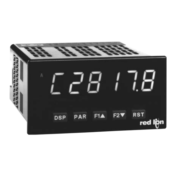
MODEL PAXDR - 1/8 DIN DUAL RATE METER / TOTALIZER
GENERAL DESCRIPTION
The PAXDR is a 5-digit Dual Rate Indicator and 6-digit Dual Totalizer in a
single meter. Two Rate and two Total displays are provided (A and B), along
with two additional calculation displays (C) to show the Sum, Difference, Ratio,
% of Total or Draw between A and B displays. Any of the six displays are
viewable: A, B or C Rate and A, B or C Total. The meter's LED display has
0.56" digits, available in red sunlight readable or standard green. The display
intensity is adjustable for low level lighting conditions up to sunlight readable
applications.
The meter has two signal inputs from which the Rate and Totalizer values are
derived. For the Rate displays, up to 10 point scaling is provided for each input,
to scale non-linear rate processes. Separate scaling is provided for both the A
and B Totalizers. The independent scaling allows for Rate only, Totalizer only
or combination Rate/Totalizer applications, with or without the calculation
displays.
While suitable for many applications, this meter is ideal for flow measurement
where both flow rate and flow volume are measured. Two separate flow lines
can be monitored simultaneously, each scaled to convert flow to a common unit
of measure. Flow rate is easily scaled to read flow per time period (sec/min/hr).
The flow rate and volume for each line can be shown, as well as the Sum,
Difference, Ratio, etc. between the two lines for flow rate and/or volume. A
different calculation function may be used for Rate and Total if desired.
Optional plug-in cards provide up to four setpoint outputs, a linear DC output
and communications capability. The Plug-in setpoint cards provide dual
FORM-C relays (5 A), quad FORM-A relays (3 A), or either quad sinking or
quad sourcing open collector logic outputs. The outputs can be assigned to any
of the Rate or Totalizer display values, and configured to suit a variety of control
and alarm requirements.
DIMENSIONS In inches (mm)
8. 8 . 8 . 8 . 8 . 8
A
B
C
SP1
SP2
DSP
PAR
F1
3.80
(96.5)
Courtesy of Steven Engineering, Inc.-230 Ryan Way, South San Francisco, CA 94080-6370-Main Office: (650) 588-9200-Outside Local Area: (800) 258-9200-www.stevenengineering.com
Note: Recommended minimum clearance (behind the panel) for
1.95
(49.5)
SP3
SP4
F2
RST
.10
(2.5)
SIX DISPLAYS - ONE EACH FOR: RATE A & B; TOTALIZER A & B;
DISPLAY C RATE CALCULATION & TOTALIZER CALCULATION
DISPLAY C CALCULATIONS: SUM (A+B), DIFFERENCE (A-B),
RATIO (A/B), % OF TOTAL (A/A+B) OR DRAW (A-B/B)
0.56" RED SUNLIGHT READABLE DISPLAY
VARIABLE INTENSITY DISPLAY
10 POINT NON-LINEAR SCALING FOR BOTH RATE DISPLAYS
SEPARATE INPUT SCALING FOR A AND B TOTALIZERS
PROGRAMMABLE FUNCTION KEYS/USER INPUTS
FOUR SETPOINT ALARM OUTPUTS (W/Option Card)
RETRANSMITTED ANALOG OUTPUT (W/Option Card)
COMMUNICATION AND BUS CAPABILITIES (W/Option Card)
NEMA 4X/IP65 SEALED FRONT BEZEL
The linear DC output Plug-in card provides either 20 mA or 10 V signals. The
output can be scaled independent of the input range and can track any of the
Rate or Totalizer displays.
Communication and Bus Capabilities are also available as option cards.
These include RS232, RS485, Modbus, DeviceNet and Profibus-DP. Readout
values and setpoint alarm values can be controlled through the bus. Additionally,
the meter has a feature that allows a remote serial device to directly control the
meter outputs.
The PAXDR is available in AC or DC powered versions. The meter has been
specifically designed for harsh industrial environments. With NEMA 4X/IP65
sealed bezel and extensive testing to meet CE requirements, the meter provides
a tough yet reliable application solution.
SAFETY SUMMARY
All safety related regulations, local codes and instructions that appear in this
literature or on equipment must be observed to ensure personal safety and to
prevent damage to either the instrument or equipment connected to it. If
equipment is used in a manner not specified by the manufacturer, the protection
provided by the equipment may be impaired.
Do not use this meter to directly command motors, valves, or other actuators
not equipped with safeguards. To do so can be potentially harmful to persons or
equipment in the event of a fault to the meter.
CAUTION: Risk of Danger.
Read complete instructions prior to
installation and operation of the unit.
mounting clip installation is 2.1" (53.4) H x 5" (127) W.
4.10
(104.1)
1
CAUTION: Risk of electric shock.
12
16
13
17
14
18
1.75
15
19
(44.5)
1
2
3
4
5
6
7
8
9
10
11
3.60 (91.4)
Bulletin No. PAXDR-X
Drawing No. LP0812
Effective 09/09
20
21
22
1.75
23
24
(44.5)
25
Advertisement
Table of Contents

Related Manuals for red lion PAXDR Series


Summary of Contents for red lion PAXDR Series
- Page 1 Bulletin No. PAXDR-X Drawing No. LP0812 Effective 09/09 Tel +1 (717) 767-6511 Fax +1 (717) 764-0839 www.redlion.net MODEL PAXDR - 1/8 DIN DUAL RATE METER / TOTALIZER SIX DISPLAYS - ONE EACH FOR: RATE A & B; TOTALIZER A & B; DISPLAY C RATE CALCULATION &...
-
Page 2: Table Of Contents
ABLE ONTENTS Ordering Information ....2 Reviewing the Front Buttons and Display ..9 Meter Specifications ....3 Programming the Meter. -
Page 3: Meter Specifications
2. Criterion C: Temporary loss of function where system reset occurs. sources including switch contacts, TTL outputs, magnetic pickups and all Refer to the EMC Installation Guidelines section of the bulletin for standard Red Lion sensors. additional information. Logic: Input trigger levels V = 1.5 V max.;... -
Page 4: Optional Plug-In Output Cards
PTIONAL UTPUT ARDS WARNING: Disconnect all power to the unit before SETPOINT CARDS (PAXCDS) installing Plug-in cards. The PAX and MPAX series has 4 available setpoint alarm output plug-in cards. Only one of these cards can be installed at a time. (Logic state of the outputs can be reversed in the programming.) These plug-in cards include: Adding Option Cards PAXCDS10 - Dual Relay, FORM-C, Normally open &... -
Page 5: Installing The Meter
1.0 I NSTALLING THE ETER While holding the unit in place, push the panel latch over the rear of the unit Installation so that the tabs of the panel latch engage in the slots on the case. The panel The PAX meets NEMA 4X/IP65 requirements when properly installed. The latch should be engaged in the farthest forward slot possible. -
Page 6: Installing Plug-In Cards
3.0 I NSTALLING ARDS The Plug-in cards are separately purchased optional cards that perform To Install: specific functions. These cards plug into the main circuit board of the meter. The 1. With the case open, locate the Plug-in card connector for the card type to be Plug-in cards have many unique functions when used with the PAX. -
Page 7: Wiring The Meter
4.0 W IRING THE ETER b. Connect the shield to earth ground at both ends of the cable, usually when WIRING OVERVIEW the noise source frequency is above 1 MHz. Electrical connections are made via screw-clamp terminals located on the c. - Page 8 4.3 INPUT WIRING CAUTION: Sensor input common is NOT isolated from user input common. In order to preserve the safety of the meter application, the sensor input common must be suitably isolated from hazardous live earth referenced voltage; or input common must be at protective earth ground potential. If not, hazardous voltage may be present at the User Inputs and User Input Common terminals.
-
Page 9: Reviewing The Front Buttons And Display
4.5 SERIAL COMMUNICATION WIRING RS232 Communications RS485 Communications The RS485 communication standard allows the connection of up to 32 devices on a single pair of wires, distances up to 4,000 ft. and data rates as high RECEIVING DEVICE PAX METER (DTE) as 10M baud (the PAX is limited to 19.2k baud). -
Page 10: Programming The Meter
6.0 P ROGRAMMING THE ETER OVERVIEW DISPLAY MODE PROGRAMMING MENU User Input/ Display/ Rate Function Program Totalizer A Totalizer C Setpoint* Serial* Analog* Factory Setup Lock-out and B Setup Setup (Alarm) Communications Output Service Parameters Parameters Parameters Parameters Parameters Parameters Parameters Parameters Operations... - Page 11 6.1 MODULE 1 - R ETUP ARAMETERS 1-rAtE PARAMETER MENU LO-Udt HI-Udt C rAtE C SCLr C dPt C LIt x dPt x SE6S xdSP # xINP # x rnd Low Update High Update Rate C Rate C Display Rate C Rate C Rate x...
- Page 12 Non-linear Application – Up to 10 Scaling Points RATE A INPUT VALUE FOR SCALING POINT 2 Non-linear processes may utilize up to nine segments (ten scaling points) to provide a piece-wise linear approximation representing the non-linear function. ...
- Page 13 INPUT FREQUENCY CALCULATION RATE B DISPLAY VALUE FOR SCALING POINT 2 The meter determines the input frequency by summing the number of falling edges received during a sample period of time. The sample period begins on the ...
- Page 14 6.2 MODULE 2 - U NPUT AND RONT ANEL UNCTION ARAMETERS 2-FNC PARAMETER MENU USr-1 USr-2 USr-3 SC-F1 SC-F2 USER INPUTS FUNCTION KEYS Module 2 is the programming for rear terminal user inputs and front panel RESET DISPLAY function keys. Three rear terminal user inputs are individually programmable to perform ...
- Page 15 TOTALIZER MAINTAINED (LEVEL) RESET AND INHIBIT HOLD SETPOINT STATE The meter holds the state of the setpoints configured as , as long as The meter performs a reset and inhibits the totalizer displays configured as ...
- Page 16 6.3 MODULE 3 - D ISPLAY AND ROGRAM ARAMETERS 3-LOC PARAMETER MENU bCntLd rAtE SP-n ACntLd SCFAC COdE Rate x Totalizer x Totalizer A Totalizer B Totalizer x Setpoint 1-4 Security Count Load Display Count Load Scale Factor Display Access Code Lock-out...
- Page 17 6.4 MODULE 4 - T A & B S OTALIZER ETUP ARAMETERS PARAMETER MENU 4-tot x tot x P-UP xrESEt xdECPt xSCFAC xSCALr xCntLd Totalizer x Totalizer x Totalizer x Totalizer x Totalizer x Totalizer x Totalizer x Operating Reset Action Decimal Scale Factor...
- Page 18 TOTALIZER B OPERATING MODE TOTALIZER B RESET AT POWER-UP Totalizer B may be programmed to reset at each meter power-up. Select the operating mode for Totalizer B. SELECTION MODE DESCRIPTION...
- Page 19 6.5 MODULE 5 - T OTALIZER ETUP ARAMETERS 5-totC PARAMETER MENU C tot CdECPt CSCFAC CSCALr C P-UP Totalizer C Totalizer C Totalizer C Totalizer C Totalizer C Calculation Decimal Scale Factor Scale Reset at Position Multiplier Power-up Module 5 is the programming for Totalizer C. For maximum input frequency, the Totalizer C Calculation should be set to when not in use.
- Page 20 6.6 MODULE 6 - S ETPOINT LARM ARAMETERS 6-SPt PARAMETER MENU SPSEL OUt-n LIt-n ASN-n ACt-n SUP-n SP-n trC-n tYP-n Setpoint Output Setpoint Setpoint Setpoint Power-up Setpoint Setpoint Boundary Select Logic Annunciator Assignment Action State Value Tracking Type Stb-n HYS-n tOFF-n tON-n...
- Page 21 SETPOINT ACTION SETPOINT BOUNDARY TYPE activates the output when the assigned display value ( ) equals or : When not using a setpoint, it should be set to (no action).
- Page 22 TOTALIZER AUTO RESET SETPOINT RESET WHEN SPn+1 ACTIVATES Select , so the setpoint output will deactivate (reset) when SPn +1 This parameter automatically resets the Setpoint Assigned Totalizer (A or B) ...
- Page 23 6.7 MODULE 7 - S ERIAL OMMUNICATIONS ARAMETERS PARAMETER MENU 7-SrL bAUd dAtA Addr Abbr Baud Rate Data Bit Parity Bit Meter Abbreviated Print Address Printing Options A rAtE b rAtE C rAtE Ab tot SCFAC C tot CntLd Print Print Print...
- Page 24 SENDING SERIAL COMMANDS AND DATA Command String Examples: 1. Address = 17, Write 350 to Setpoint 1 When sending commands to the meter, a string containing at least one String: N17VM350$ command character must be constructed. A command string consists of a command character, a value identifier, numerical data (if writing data to the 2.
- Page 25 Auto/Manual Mode Register (MMR) ID: U Writing to this register (VW) while the analog output is in the Manual Mode This register sets the controlling mode for the outputs. In Auto Mode (0) the causes the output signal level to update immediately to the value sent. While in meter controls the setpoint and analog output.
- Page 26 COMMUNICATION FORMAT Data is transferred from the meter through a serial communication channel. In serial communications, the voltage is switched between a high and low level at a predetermined rate (baud rate) using ASCII encoding. The receiving device reads the voltage levels at the same intervals and then translates the switched levels back to a character.
-
Page 27: Factory Service Operations
6.9 MODULE 9 - F ACTORY ERVICE PERATIONS 9-FCS PARAMETER MENU d-LEV COdE Display Factory Intensity Level Service Code DISPLAY INTENSITY LEVEL Analog Output Card Calibration Before starting, verify that a precision meter with an accuracy of 0.05% or Enter the desired Display Intensity Level (0-15) by ... -
Page 28: Parameter Value Chart
PARAMETER VALUE CHART Programmer ________________ Date ________ PAXDR Model Number _________ Meter# _____________ Security Code __________ Rate Setup Parameters User Input and Function Key Parameters FACTORY USER FACTORY DISPLAY PARAMETER DISPLAY PARAMETER USER SETTING SETTING SETTING SETTING ... - Page 29 Totalizer C Setup Parameters Analog Output Parameters FACTORY FACTORY DISPLAY PARAMETER USER SETTING DISPLAY PARAMETER USER SETTING SETTING SETTING TOTALIZER C CALCULATION ANALOG TYPE TOTALIZER C DECIMAL POSITION ANALOG ASSIGNMENT ...
- Page 30 This page intentionally left blank. Courtesy of Steven Engineering, Inc.-230 Ryan Way, South San Francisco, CA 94080-6370-Main Office: (650) 588-9200-Outside Local Area: (800) 258-9200-www.stevenengineering.com...
-
Page 31: Programming Overview
PAXDR PROGRAMMING QUICK OVERVIEW Courtesy of Steven Engineering, Inc.-230 Ryan Way, South San Francisco, CA 94080-6370-Main Office: (650) 588-9200-Outside Local Area: (800) 258-9200-www.stevenengineering.com... - Page 32 The Company disclaims all liability for any affirmation, promise or representation with respect to the products. The customer agrees to hold Red Lion Controls harmless from, defend, and indemnify RLC against damages, claims, and expenses arising out of subsequent sales of RLC products or products...
Need help?
Do you have a question about the PAXDR Series and is the answer not in the manual?
Questions and answers