Table of Contents
Advertisement
Tel +1 (717) 767-6511
Fax +1 (717) 764-0839
www.redlion-controls.com
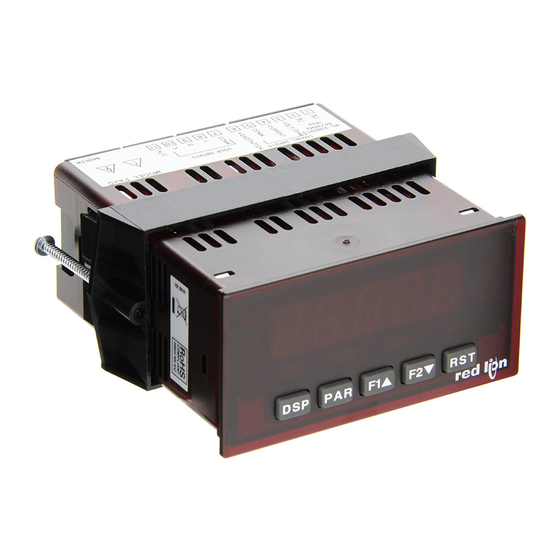
MODEL PAXI-1/8 DIN COUNTER/RATE PANEL METER
UL Recognized Component,
File # E179259
GENERAL DESCRIPTION
The PAXI (PAX Counter/Rate Panel Meter) offers many features and
performance capabilities to suit a wide range of industrial applications. The
Plug-in options cards allow the opportunity to configure the meter for present
applications, while providing easy upgrades for future needs.
The PAXI meter accepts digital inputs from a variety of sources including
switch contacts, outputs from CMOS or TTL circuits, magnetic pickups and all
standard RLC sensors. The meter can accept directional, uni-directional or
Quadrature signals simultaneously. The maximum input signal varies up to 34
KHz depending on the count mode and function configurations programmed.
Each input signal can be independently scaled to various process values.
The meter provides six different display indications. These include Counter
A, Counter B, Counter C (or slave display), Rate, Rate Maximum (High) and
Rate Minimum (Low). Counter A and/or Counter B indicate the corresponding
input count value. Counter C indicates the sum or difference between Counter
A and Counter B values or can be programmed to be a Serial Slave Display. The
Rate display can be programmed to show the speed of Counter A or Counter B.
The Maximum and Minimum displays can indicate the peaks and valleys of the
speed with programmable capture times to prevent false detection.
Annunciators indicate which display is being shown.
The front panel keys and three user inputs are programmable to perform
various meter functions. One of the functions includes exchanging parameter
lists, allowing double the number of programmable setpoint, scale factor and
count load values.
The meter can have up to four setpoint outputs, determined by the Plug-in
cards. The Plug-in cards provide dual FORM-C relays (5A), quad FORM-A
relays (3A) or either quad sinking or quad sourcing open collector logic outputs.
The outputs can be assigned to any of the four displays. The outputs can also be
independently configured to suit variety of control and alarm requirements.
DIMENSIONS In inches (mm)
6-DIGIT LED DISPLAY (Alternating 8 digits for counting)
!
DUAL COUNT QUAD INPUTS
!
RATE INDICATION
!
UP TO 3 COUNT DISPLAYS OR A SERIAL SLAVE
!
PROGRAMMABLE SCALE FACTORS
!
PROGRAMMABLE FUNCTION KEYS / USER INPUTS
!
FOUR SETPOINT ALARM OUTPUTS (W/Plug-in card)
!
COMMUNICATIONS AND BUS CAPABILITIES (W/Plug-in card)
!
ANALOG OUTPUT SIGNAL (W/Plug-in card)
!
PC SOFTWARE AVAILABLE FOR METER CONFIGURATION
!
NEMA 4X/IP65 SEALED FRONT BEZEL
!
A linear DC output signal is available as a Plug-in card. The card provides
either 20 mA or 10 V signals. The analog output can be assigned to any of the
six displays and is scalable.
Plug-in cards can also provide serial communications. These include RS232,
RS485 and MODBUS. Display values, setpoint alarm values and setpoint states
can be controlled through the serial loop. With the communications card
installed, it is possible to configure the meter using a Windows
The meter configuration data can be saved to a file for later recall.
Once the meter has been initially configured, the parameter list may be
locked out from further modification entirely or the setpoint, scale factor and
count load values can be made accessible. This lockout is possible through a
security code or user input.
The meter has been specifically designed for harsh industrial environments.
With a NEMA 4X/IP65 sealed bezel and extensive testing to meet CE
requirements, the meter provides a tough yet reliable application solution.
SAFETY SUMMARY
All safety related regulations, local codes and instructions that appear in this
literature or on equipment must be observed to ensure personal safety and to
prevent damage to either the instrument or equipment connected to it. If
equipment is used in a manner not specified by the manufacturer, the protection
provided by the equipment may be impaired.
Do not use this meter to directly command motors, valves, or other actuators
not equipped with safeguards. To do so can be potentially harmful to persons or
equipment in the event of a fault to the unit.
instructions prior to installation
and operation of the unit.
Note: Recommended minimum clearance (behind the panel) for
mounting clip installation is 2.1" (53.4) H x 5" (127) W.
1
CAUTION: Read complete
Bulletin No. PAXI-C
Drawing No. LP0487
Revised 4/01
®
based program.
CAUTION: Risk of electric shock.
Advertisement
Table of Contents

Related Manuals for red lion PAXI-1/8


Summary of Contents for red lion PAXI-1/8
- Page 1 Revised 4/01 Tel +1 (717) 767-6511 Fax +1 (717) 764-0839 www.redlion-controls.com MODEL PAXI-1/8 DIN COUNTER/RATE PANEL METER 6-DIGIT LED DISPLAY (Alternating 8 digits for counting) DUAL COUNT QUAD INPUTS RATE INDICATION UP TO 3 COUNT DISPLAYS OR A SERIAL SLAVE...
- Page 2 SPECIFICATIONS 10. PRESCALER OUTPUT: NPN Open Collector: I = 100 mA max. @ V = 1 VDC max. V = 30 DISPLAY: 6 digit, 0.56" (14.2 mm) red LED VDC max. With duty cycle of 25% min. and 50% max. 2.
- Page 3 15 CERTIFICATIONS AND COMPLIANCE: 16. ENVIRONMENTAL CONDITIONS: UL Recognized Component, File #E179259 Operating Temperature Range: 0 to 50°C (0 to 45°C with all three plug-in Recognized to U.S. and Canadian requirements under the Component cards installed) Recognition Program of Underwriters Laboratories, Inc. Storage Temperature range: -40 to 60°C SAFETY Operating and Storage Humidity: 0 to 85% max.
-
Page 4: Installing The Meter
OPTIONAL PLUG-IN CARDS AND ACCESSORIES The PAX series meters can be fitted with up to three optional plug-in cards. However, only one card from each function type can be installed at a time. The function types include Setpoint Alarms (PAXCDS), Communications MODBUS PLUG-IN CARD (PAXCDC) (PAXCDC), and Analog Output (PAXCDL). -
Page 5: Setting The Jumper And Dip Switches
2.0 SETTING THE JUMPER AND DIP SWITCHES To access the jumper and switches, remove the meter base from the meter Warning: Exposed line voltage exists on the circuit boards. Remove case by firmly squeezing and pulling back on the side rear finger tabs. This all power to the meter and load circuits before accessing inside of should lower the latch below the case slot (which is located just in front of the the meter. -
Page 6: Wiring The Meter
4.0 WIRING THE METER WIRING OVERVIEW Electrical connections are made via screw-clamp terminals located on the c. Connect the shield to common of the meter and leave the other end of the back of the meter. All conductors should conform to the meter’s voltage and shield unconnected and insulated from earth ground. - Page 7 4.3 INPUT WIRING CAUTION: Sensor input common is NOT isolated from user input common. In order to preserve the safety of the meter application, the sensor input common must be suitably isolated from hazardous live earth referenced voltage; or input common must be at protective earth ground potential. If not, hazardous voltage may be present at the User Inputs and User Input Common terminals.
-
Page 8: Reviewing The Front Buttons And Display
4.5 SERIAL COMMUNICATION WIRING RS232 Communications RS485 Communications The RS485 communication standard allows the connection of up to 32 devices on a single pair of wires, distances up to 4,000 ft. and data rates as high as 10M baud (the PAX is limited to 19.2k baud). The same pair of wires is used to both transmit and receive data. -
Page 9: Programming The Meter
6.0 PROGRAMMING THE METER OVERVIEW PROGRAMMING MENU PROGRAMMING MODE ENTRY (PAR KEY) PROGRAMMING MODE EXIT (DSP KEY or at PAR KEY) The meter normally operates in the Display Mode. No parameters can be -!/ +$ programmed in this mode. The Programming Mode is entered by pressing the The Programming Mode is exited by pressing the DSP key (from anywhere PAR key. - Page 10 COUNTER A OPERATING MODE COUNTER A SCALE MULTIPLIER * " 3(&3#! " 3 &+' NONE cntud dcntud quAd1 quAd2 8: 4 8: 8 4 quAd4 dquAd1 dquAd2 cnt2 cntud2 dctud2 The number of input counts is multiplied by the scale multiplier and the scale Select the operating mode for Counter A.
- Page 11 COUNTER B OPERATING MODE COUNTER B RESET POWER-UP * " , -59- " , &+' NONE dcntud dquAd1 >)( dquAd2 cnt2 dctud2 Counter B may be programmed to reset at each meter power-up. Select the operating mode for Counter B. Factory Setting can be used without affecting basic start-up.
- Page 12 6.2 MODULE 2 - User Input and Front Panel Function Key Parameters ( ?5%+& PARAMETER MENU Module 2 is the programming for rear terminal user inputs and front panel RESET DISPLAY function keys. " " 9(!54 Three rear terminal user inputs are individually programmable to perform specific meter control functions.
- Page 13 PRINT REQUEST AND RESET DISPLAYS STORE DISPLAY " " " " 9(!54 9(!54 -!+!(' -!+!(' ('$!) ('$!) The meter issues a block print through the serial port when activated just like The meter holds (freeze) the displays configured as >)( , as long as activated the Print Request function.
- Page 14 6.3 MODULE 3 - Display and Program Lock-out Parameters ( @5#$& PARAMETER MENU x = Counter A , Counter B, and then Counter C n = Setpoints 1 to 4 Module 3 is the programming for Display lock-out and “Full” and “Quick” SETPOINT 1 to 4 ACCESS LOCK-OUT * Program lock-out.
- Page 15 6.4 MODULE 4 - Rate Input Parameters ( A5!') PARAMETER MENU Non-linear Application – Up to 10 Scaling Points Module 4 is the programming for the Rate parameters. For maximum input frequency, Rate assignment should be set to when not in use. When set to Non-linear processes may utilize up to nine segments (ten scaling points) to , the remaining related parameters are not accessible.
- Page 16 RATE INPUT VALUE FOR SCALING POINT 2 RATE SCALING To scale the Rate, enter a Scaling Display value with a corresponding Scaling " !*+- 4 =====: = Input value. (The Display and Input values can be entered by Key-in or Applied Methods.) These values are internally plotted to a Display value of 0 and Input 4888: 8 value of 0 Hz.
- Page 17 6.5 MODULE 5 - Counter C Input Parameters ( 75&'!& PARAMETER MENU Module 5 is the programming for Counter C. For maximum input frequency, the counter operating mode should be set to +$+) when not in use. When set to COUNTER C SCALE FACTOR +$+) the remaining related parameters are not accessible.
- Page 18 6.6 MODULE 6 - Setpoint (Alarm) Parameters ( B5(-' PARAMETER MENU Module 6 is the programming for the setpoint (alarms) output parameters. To have setpoint outputs, a setpoint Plug-in card needs to be installed into the PAXI (see Ordering Information). Depending on the card installed, there will be two or four setpoint outputs available.
- Page 19 SETPOINT ACTION SETPOINT HYSTERESIS * " " 3&'52 ">(52 ==== #3'&" '$9' ,$9+. '$9' The hysteresis value is added to (for '>6 #$), or subtracted from (for '>6 : When not using a setpoint, it should be set to (no action). "*), the setpoint value to determine at what value to deactivate the associated For Counter Assignments: setpoint output.
- Page 20 SETPOINT RESET WHEN SPn+1 ACTIVATES * SETPOINT RESET WHEN SPn+1 DEACTIVATES * " " !(3(52 !(3)52 >)( >)( Select >)( , so the setpoint output will deactivate (reset) when SPn +1 Select >)( , so the setpoint output will deactivate (reset) when SPn +1 activates.
- Page 21 6.7 MODULE 7 - Serial Communications Parameters ( C5(!# PARAMETER MENU To establish serial communications, it is necessary to: ABBREVIATED PRINTING 1. Have a serial communications plug-in card installed into the PAXI (See " 3,!; Ordering Information). >)( 2. Have the proper serial wiring, connections, and if needed, a serial converter. (See Section 4.5 Serial Communication Wiring).
- Page 22 SENDING SERIAL COMMANDS AND DATA Command String Examples: 1. Address = 17, Write 350 to Setpoint 1 When sending commands to the meter, a string containing at least one String: N17VM350$ command character must be constructed. A command string consists of a command character, a value identifier, numerical data (if writing data to the 2.
- Page 23 Auto/Manual Mode Register (MMR) ID: U Writing to this register (VW) while the analog output is in the Manual Mode causes the output signal level to update immediately to the value sent. While in This register sets the controlling mode for the outputs. In Auto Mode (0) the the Automatic Mode, this register may be written to, but it has no effect until the meter controls the setpoint and analog output.
- Page 24 COMMAND RESPONSE TIME SERIAL TIMING The meter can only receive data or transmit data at any one time (half-duplex PROCESS TIME (t COMMAND COMMENT operation). During RS232 transmissions, the meter ignores commands while Numeric Slave 2-50 msec. transmitting data, but instead uses RXD as a busy signal. When sending Reset 2-50 msec.
- Page 25 6.8 MODULE 8 - Analog Output Parameters ( D53+3 PARAMETER MENU Module 8 is the programming for the analog output parameters. To have an analog output signal, an analog output plug-in card needs to be installed (See ANALOG LOW SCALE VALUE Ordering Information).
-
Page 26: Troubleshooting
TROUBLESHOOTING For further assistance, contact technical support at the appropriate company numbers listed. PROBLEM REMEDIES NO DISPLAY CHECK: Power level, power connections CHECK: Active (lock-out) user input PROGRAM LOCKED-OUT ENTER: Security code requested CERTAIN DISPLAYS ARE LOCKED OUT CHECK: Module 3 programming CHECK: Input wiring, DIP switch setting, input programming, scale factor calculation, INCORRECT DISPLAY VALUE or NOT COUNTING... - Page 27 The customer agrees to hold Red Lion Controls harmless from, defend, and indemnify RLC against damages, claims, and expenses arising out of subsequent sales of RLC products or products containing components manufactured by...
- Page 28 F1/F2 Keys &+' !)()' .)&-' (&%3& (&3#! &+'#. -59- 45*+- -!()+ -!;3# Counter x Counter x Counter x Counter x Counter x Counter x Counter x Prescaler Prescaler Operating Reset Decimal Scale Scale Count Load Reset at Output Scale Mode Action Position Factor...
Need help?
Do you have a question about the PAXI-1/8 and is the answer not in the manual?
Questions and answers