Table of Contents
Advertisement
Quick Links
Tel +1 (717) 767-6511
Fax +1 (717) 764-0839
www.redlion.net
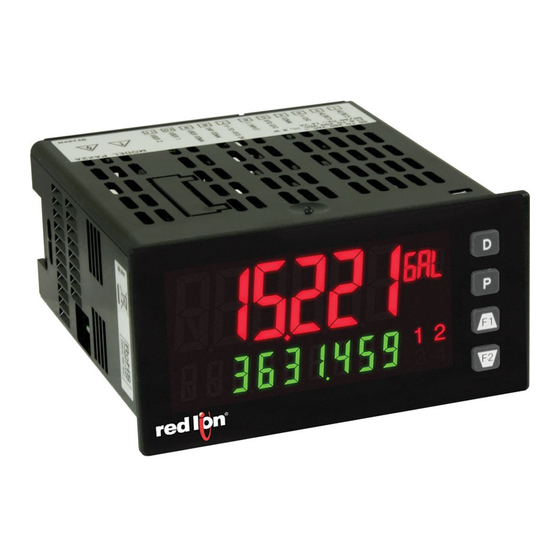
MODEL PAX2A – 1/8 DIN ANALOG PANEL METER
DESCRIPTION
The PAX2A Analog Panel Meter offers many features and performance
capabilities to suit a wide range of industrial applications. The PAX2A has a
universal input to handle various input signals including DC Voltage/Current,
Process, Resistance and Temperature. The optional plug-in output cards allow
the opportunity to configure the meter for present applications, while providing
easy upgrades for future needs. The PAX2A employs a dual line, tri color
display with a large 0.71", tri color 6 digit top display line and a 0.35", 9 digit
green bottom display line.
The meters provide a MAX and MIN reading memory with programmable
capture time. The capture time is used to prevent detection of false max or min
readings which may occur during start-up or unusual process events.
The signal totalizer (integrator) can be used to compute a time-input product.
This can be used to provide a readout of totalized flow or calculate service
intervals of motors, pumps, etc. The meters have up to four setpoint outputs,
implemented on plug-in option cards. The plug-in cards provide dual FORM-C
relays (5A), quad FORM-A (3A), or either quad sinking or quad sourcing open
collector logic outputs. The setpoint alarms can be configured to suit a variety
of control and alarm requirements.
Communication and bus capabilities are also available as option cards. These
include RS232, RS485, DeviceNet, and Profibus-DP. The PAX2A can be
programmed to utilize ModBus protocol. With ModBus, the user has access to
most configuration parameters. Readout values and setpoint alarm values can be
controlled through the bus. Additionally, the meters have a feature that allows a
remote computer to directly control the outputs of the meter.
The PAX2A includes a built-in USB programming port that makes it possible
to configure the meter using a Windows
communication option cards. The configuration data can be saved to a file for
later recall.
DIMENSIONS In inches (mm)
1.95
(49.53)
3.80 (96.52)
®
based program, without any additional
Note: Recommended minimum clearance (behind the panel) for
mounting clip installation is 2.1" (53.4) H x 5.5" (140) W.
0.10
(2.54)
UNIVERSAL PROCESS, VOLTAGE, CURRENT, RESISTANCE
AND TEMPERATURE INPUTS
UNIVERSAL AC/DC POWER SUPPLY
6 / 9 DIGIT DUAL LINE/COLOR DISPLAY W/ 0.71" & 0.35" DIGITS
PROGRAMMABLE UNITS DISPLAY
VARIABLE CONTRAST AND INTENSITY DISPLAY
UP TO 160 SAMPLES PER SECOND CONVERSION RATE
BUILT-IN USB PROGRAMMING PORT ENABLING UNIT
CONFIGURATION WITH CRIMSON PROGRAMMING SOFTWARE
A linear DC output signal is available as an optional plug-in card. The card
provides either 20 mA or 10 V signals. The output can be scaled independent of
the input range and can track either the input, totalizer, max or min readings.
Once the meters have been initially configured, the parameter list may be locked
out from further modification in its entirety or partially locked allowing the
setpoint values to remain accessible.
The meters have been specifically designed for harsh industrial environments.
With NEMA 4X/IP65 sealed bezel and extensive testing of noise effects and CE
requirements, the meter provides a tough yet reliable application solution.
SAFETY SUMMARY
All safety related regulations, local codes and instructions that appear in this
literature or on equipment must be observed to ensure personal safety and to
prevent damage to either the instrument or equipment connected to it. If
equipment is used in a manner not specified by the manufacturer, the protection
provided by the equipment may be impaired. Do not use this unit to directly
command motors, valves, or other actuators not equipped with safeguards. To do
so can be potentially harmful to persons or equipment in the event of a fault to
the unit.
CAUTION: Risk of Danger.
Read complete instructions prior to
installation and operation of the unit.
1.75
(44.45)
4.14 (105)
1
Bulletin No. PAX2A-(x)
Drawing No. LP0830
Effective 08/10
CAUTION: Risk of electric shock.
PANEL CUT-OUT
3.60 (91.44)
Advertisement
Table of Contents

Related Manuals for red lion PAX2A


Summary of Contents for red lion PAX2A
- Page 1 The PAX2A has a Once the meters have been initially configured, the parameter list may be locked...
-
Page 2: Table Of Contents
Optional Plug-In Cards ....5 PAX2A Display Loops ....10 Installing the Meter . -
Page 3: General Meter Specifications
ENERAL ETER PECIFICATIONS 1. DISPLAY: Positive image LCD THERMOCOUPLE INPUTS: Top Line - 6 digit, 0.71" (18 mm), with tri-color backlight (red, green or Input Impedance: 20M orange), display range: -199999 to 999999; Lead Resisitance Effect: 0.03 %V/ Bottom Line - 9 digit, 0.35" (8.9 mm), with green backlight, display range: Max Continuous Overvoltage: 30 V - 199,999,999 to 999,999,999 WIRE COLOR... - Page 4 14. ENVIRONMENTAL CONDITIONS: Logic State: User programmable (USrACt) for sink/source (LO/HI) logic Operating Temperature Range: 0 to 50 °C (0 to 45 °C with all three plug-in INPUT STATE SINKING INPUTS SOURCING INPUTS cards installed) 20K pull-up to +3.3V 20K pull-down Storage Temperature Range: -40 to 60 °C Operating and Storage Humidity: 0 to 85% max.
-
Page 5: Optional Plug-In Cards
These plug-in cards include: Adding Option Cards The PAX2A meters can be fitted with up to three optional plug-in cards. The PAXCDS10 - Dual Relay, FORM-C, Normally open & closed details for each plug-in card can be reviewed in the specification section below. -
Page 6: Installing The Meter
2.0 S ETTING THE UMPERS The PAX2A meter has four jumpers that must be checked and/or changed Warning: Exposed line voltage exists on the circuit boards. Remove prior to applying power. The following Jumper Selection Figures show an all power to the meter and load circuits before accessing inside of enlargement of the jumper area. -
Page 7: Installing The Plug-In Cards
When installing the card, hold the meter by the rear states in the plug-in card literature that the information applies to the PAX2A. terminals and not by the front display board.* 2. - Page 8 4.1 POWER WIRING AC Power DC Power AC/DC AC/DC AC/DC AC/DC AC/DC AC/DC 4.2 VOLTAGE/OHMS/CURRENT INPUT SIGNAL WIRING Before connecting signal wires, the Input Range Jumper and Excitation Jumper should be verified for proper position. Voltage Signal Process/Current Process/Current Signal Current Signal (3 wire (self powered) Signal...
-
Page 9: Reviewing The Front Buttons And Display
*Factory setting for F1 and F2 is no mode The PAX2A display consists of a large, 6-digit upper display referred to as Line 1 and a smaller 9-digit lower display referred to as Line 2. The upper display (LinE 1) can be configured to show a single value, i.e., the main input reading, Min, Max, or total values. The lower display (Ln2) can be used to display several selectable values including;... -
Page 10: Pax2A Display Loops
When the P key is pushed on a resettable display, the unit will display the value The PAX2A offers three display loops to allow users quick access to needed mnemonic and “NO” (if Line 2 value was set for “P-ENt” or “d-ENt” in information. -
Page 11: Programming The Pax2A
COdE INVALID CODE VALID CODE 0. 0 500. 0 hidE Hidden Parameters 0. 0 Display 0. 0 Loop hidE 1-INPUt 6.0 P PAX2A ROGRAMMING 1-INPUt 2-FUNCt 3-dISPLY 4-SCNdrY 5-totAL 6-SEtPNt 7-SErIAL 8-AnLOut 9-FACtrY Signal User Input/ Display/ Secondary Totalizer Setpoint... - Page 12 MODULE 1 - I NPUT ETUP ARAMETERS 1-INPUt PARAMETER MENU 1-INPUt Temperature Input Types Only rANGE SCALE rAtE dECPNt round OFFSEt 200U °F 0. 0 0 0. 0 1 0. 0 0 Input Range Temperature Ice Point ADC Rate Display Display Display Scale...
- Page 13 between and continue past the entered points up to the limits of the Input Signal DISPLAY VALUE FOR SCALING POINT 1 Jumper position. Each scaling point has a coordinate-pair of Input Value (INPUt dISPLY n) and an associated desired Display Value (dISPLAY n). -199999 999999 Nonlinear - Scaling Points (Greater than 2)
- Page 14 NO FUNCTION STORE BATCH READING IN TOTALIZER USEr-1 USEr-1 No function is performed if activated. This is the factory setting for all user The Input Display value is one time added (batched) to the Totalizer at inputs and function keys. No function can be selected without affecting basic transition to activate (momentary action) and Line 2 flashes bAtCh.
- Page 15 RESET MINIMUM DISPLAY SELECT PARAMETER LIST USEr-1 USEr-1 r-Lo r-Lo LISt LISt When activated (momentary action), rESEt flashes and the Minimum resets Two lists of input scaling points and setpoint values (including band and to the present Input Display value. The Minimum function then continues from deviation) are available.
- Page 16 MODULE 3 - D (3-dISPLY) ISPLAY ARAMETERS PARAMETER MENU 3-dISPLY Color d-LEV d-Cont LINE 1 UNItS ACCESS INPUt tOtAL GrEEN INPUt Display Display Display Line 1 Units Access Line 2 Input Line 2 Total Line 2 MIN Color Intensity Contrast Display Mnemonic Line 2...
- Page 17 LINE2 SETPOINTS ACCESS PROGRAMMING SECURITY CODE bn-dn COdE The Security Code determines the programming mode and the accessibility When configured for d-ENt, the P key must be pushed to select the item for of programming parameters. This code can be used along with the Program change before the UP/F1 and DN/F2 keys will increment or decrement the Mode Lock-out (PLOC) in the User Input Function parameter (Module 1).
- Page 18 MODULE 4 - S (4-SCNdrY) ECONDARY UNCTION ARAMETERS PARAMETER MENU 4-SCNdrY HI-AS HI-t LO-AS LO-t dSP-t 1. 0 1. 0 MAX Capture MAX Capture MIN Capture MIN Capture Display Assignment Time Assignment Time Update Rate MAX CAPTURE ASSIGNMENT MIN CAPTURE TIME HI-AS LO-t seconds...
- Page 19 MODULE 5 - T (5-totAL) OTALIZER NTEGRATOR ARAMETERS PARAMETER MENU 5-totAL dECPNt t bASE SCLFAC Lo Cut PWrUP 0. 0 00 1. 0 00 -199999. 9 Decimal Time Base Scale Factor Low Cut Power Up Point Value Reset The totalizer accumulates (integrates) the Input Display value using one of TOTALIZER BATCHING two modes.
- Page 20 MODULE 6 - S (6-SEtPNt) ETPOINT UTPUT ARAMETERS PARAMETER MENU 6-SEtPNt SELECt ASSIgN ACtION SEtPNt bn-dEV HYStEr t ON t OFF NONE 1. 0 0 0. 0 0 0. 0 1 0. 0 0. 0 Setpoint Setpoint Setpoint Setpoint Alternate Setpoint On Time Off Time...
- Page 21 PAX2A to use ModBus RTU protocol, 38400 baud, 8 bits, and unit address equipment are capable of transmitting and receiving. of 247 when a USB cable is attached to PAX2A and PC. The serial port settings shown in 7- SErIAL (this module) will not change, or show this.
- Page 22 USB is being used (connected), the serial communication card is disabled. The PAX2A supports both the RLC protocol and also supports ModBus communications using the standard RS232 and RS485 Pax option cards. The Pax ModBus option card should not be used with the PAX2A, as the PAX2A internal ModBus protocol supports complete unit configuration, and is much more responsive.
-
Page 23: Pax2A Modbus Register Table
The below limits are shown as Integers or HEX < > values. Read and write functions can be performed in either Integers or Hex as long as the conversion was done correctly. Negative numbers are represented by two’s complement. Note 1: The PAX2A should not be powered down while parameters are being changed. Doing so may corrupt the non-volatile memory resulting in checksum errors. REGISTER... - Page 24 REGISTER FACTORY REGISTER NAME LOW LIMIT HIGH LIMIT ACCESS COMMENTS ADDRESS SETTING INPUT PARAMETERS SEE MODULE 1 FOR PARAMETER DESCRIPTIONS 0 = 250μA 5 = 250mV 11 = 100Ω 17 = TC-K 23 = RTD 385 1 = 2.5mA 6 = 2V 12 = 1KΩ...
- Page 25 REGISTER FACTORY REGISTER NAME LOW LIMIT HIGH LIMIT ACCESS COMMENTS ADDRESS SETTING 0 = None, 1 = Input, 2 = Total, 3 = Hi, 4 = Lo, 5 = S1, 40334 Line 1 Display Read/Write 6 = S2, 7 = S3, 8 = S4 40335 Units Mnemonic Read/Write...
- Page 26 REGISTER FACTORY REGISTER NAME LOW LIMIT HIGH LIMIT ACCESS COMMENTS ADDRESS SETTING 40405 Off Time Delay 32750 Read/Write 1 = 0.1 Second 40406 Output Logic Read/Write 0 = Normal, 1 = Reverse 40407 Reset Action Read/Write 0 = Auto, 1 = Latch1, 2 = Latch2 40408 Standby Operation Read/Write...
- Page 27 Print Options (RLC only) Read/Write Value, Bit 2 – Print Max & Min Values, Bit 3 – Print Setpoint Values Changing 40481-40487 will not update the PAX2A until this register is written with a 1. After the write, the 40490 Load Serial Settings...
- Page 28 bit 3: Setpoint 4 Output Status Sending Numeric Data 0 = output off Numeric data sent to the meter must be limited to 5 digits (-19,999 to 99,999). 1 = output on If more than 5 digits are sent, the meter accepts the last 5. Leading zeros are bit 4: Manual Mode ignored.
- Page 29 COMMAND RESPONSE TIME At the start of the time interval t , the computer program prints or writes the The meter can only receive data or transmit data at any one time (half-duplex string to the com port, thus initiating a transmission. During t , the command operation).
-
Page 30: Factory Service Operations
MODULE 8 - A (8-AnLOut) NALOG UTPUT ARAMETERS PARAMETER MENU 8-AnLOut tYPE ASSIGN ANALOG ANALOG UPdAtE brnAct 4-20 NONE 0. 0 00 10. 0 00 0. 0 Analog Type Analog Output Analog Low Analog High Update Burn-out Assignment Scale Value Scale Value Time Action... - Page 32 The Company’s option. The Company disclaims all liability for any affirmation, promise or representation with respect to the products. The customer agrees to hold Red Lion Controls harmless from, defend, and indemnify RLC against damages, claims, and expenses arising out of subsequent sales of RLC products or products...
Need help?
Do you have a question about the PAX2A and is the answer not in the manual?
Questions and answers