Table of Contents
Advertisement
Quick Links
Tel +1 (717) 767-6511
Fax +1 (717) 764-0839
www.redlion-controls.com
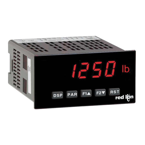
MODEL PAXR-1/8 DIN RATE PANEL METER
GENERAL DESCRIPTION
The PAXR (PAX Rate Panel Meter) offers many features and performance
capabilities to suit a wide range of industrial applications. The optional Plug-in
Setpoint Alarm Cards allow the opportunity to configure the meter for alarms if
that is a requirement.
The PAXR meter accepts digital inputs from a variety of sources including
outputs from CMOS or TTL circuits and all standard RLC sensors. The
maximum input signal is 34 KHz.
The meter provides three different display indications. These include a Rate
Display, Max Display, and Min Display. Annunciators indicate which display is
being shown.
The front panel keys and three user inputs are programmable to perform
various meter functions. One of the functions includes exchanging parameter
lists, allowing double the number of programmable setpoint.
The meter can have up to four setpoint outputs, determined by the Plug-in
cards. The Plug-in cards provide dual FORM-C relays (5 A), quad FORM-A
relays (3 A) or either quad sinking or quad sourcing open collector logic
outputs. The outputs are assigned to the rate display value. The outputs can also
be independently configured to suit a variety of control and alarm requirements.
Once the meter has been initially configured, the parameter list may be
locked out from further modification entirely, or only the setpoint can be made
accessible. This lockout is possible through a security code or user input.
The meter has been specifically designed for harsh industrial environments.
With a NEMA 4X/IP65 sealed bezel and extensive testing to meet CE
requirements, the meter provides a tough yet reliable application solution.
SAFETY SUMMARY
All safety related regulations, local codes and instructions that appear in this
literature or on equipment must be observed to ensure personal safety and to
prevent damage to either the instrument or equipment connected to it. If
equipment is used in a manner not specified by the manufacturer, the protection
provided by the equipment may be impaired.
Do not use this meter to directly command motors, valves, or other actuators
not equipped with safeguards. To do so can be potentially harmful to persons or
equipment in the event of a fault to the unit.
DIMENSIONS In inches (mm)
5-DIGIT LED DISPLAY
!
RATE INDICATION
!
PROGRAMMABLE FUNCTION KEYS / USER INPUTS
!
FOUR SETPOINT ALARM OUTPUTS (W/Plug-in card)
!
NEMA 4X/IP65 SEALED FRONT BEZEL
!
instructions prior to installation
and operation of the unit.
SPECIFICATIONS
1. DISPLAY: 5 digit, 0.56" (14.2 mm) red LED
2. POWER:
AC Versions (PAXR0000):
AC Power: 85 to 250 VAC, 50/60 Hz, 12 VA
Isolation: 2300 Vrms for 1 min. to all inputs and outputs. (300 V working)
DC Versions (PAXR0010):
DC Power: 11 to 36 VDC, 7 W
AC Power: 24 VAC, ± 10%, 50/60 Hz, 9 VA
Isolation: 500 Vrms for 1 min. to all inputs and outputs (50 V working)
3. SENSOR POWER: 12 VDC, ±10%, 100 mA max. Short circuit protected.
4. ANNUNCIATORS:
!
- Rate
"
- Maximum (High) Rate
#
- Minimum (Low) Rate
SP1 - Setpoint 1 Output State
SP2 - Setpoint 2 Output State
SP3 - Setpoint 3 Output State
SP4 - Setpoint 4 Output State
5. KEYPAD: 3 programmable function keys, 5 keys total.
6. RATE DISPLAY:
Accuracy: ± 0.01%
Minimum Frequency: 0.01 Hz
Maximum Frequency: 34 KHz
Maximum Display: 5 digits: 99999
Adjustable Display (low) Update: 0.1 to 99.9 seconds
Over Range Display: "r OLOL"
Note: Recommended minimum clearance (behind the panel) for
mounting clip installation is 2.1" (53.4) H x 5.0" (127) W.
1
UL Recognized Component,
File # E179259
CAUTION: Read complete
Bulletin No. PAXR-A
Drawing No. LP0511
Released 7/01
CAUTION: Risk of electric shock.
Advertisement
Table of Contents

Related Manuals for red lion PAXR


Summary of Contents for red lion PAXR
- Page 1 CAUTION: Risk of electric shock. that is a requirement. instructions prior to installation The PAXR meter accepts digital inputs from a variety of sources including and operation of the unit. outputs from CMOS or TTL circuits and all standard RLC sensors. The maximum input signal is 34 KHz.
-
Page 2: Ordering Information
15. WEIGHT: 10.1 oz (295 g) ORDERING INFORMATION TYPE MODEL NO. DESCRIPTION PART NUMBERS Rate Panel Meter, Upgradeable, AC Powered PAXR0000 Meter PAXR Rate Panel Meter, Upgradeable, DC/24 VAC Powered PAXR0010 Dual Setpoint Relay Output Card PAXCDS10 Optional Quad Setpoint Relay Output Card PAXCDS20 Plug-In... -
Page 3: Optional Plug-In Cards
SETPOINT ALARMS PLUG-IN CARDS (PAXCDS) Isolated quad sinking NPN open collector The PAXR series has four setpoint alarm output plug-in cards. Only one of Isolated quad sourcing PNP open collector these cards can be installed at a time. (Logic state of the outputs can be reversed in the programming.) These plug-in cards include:... -
Page 4: Installing Plug-In Cards
Plug-in Card literature that the information applies to the PAXR. 2. Install the Plug-in card by aligning the card terminals with the slot bay in the CAUTION: The Plug-in card and main circuit board contain static rear cover. -
Page 5: Power Wiring
4.1 POWER WIRING AC Power DC Power Terminal 1: VAC Terminal 1: +VDC Terminal 2: VAC Terminal 2: -VDC 4.2 USER INPUT WIRING Before connecting the wires, the User Input Logic Jumper should be verified for proper position. Only the appropriate User Input terminal has to be wired. -
Page 6: Reviewing The Front Buttons And Display
4.4 SETPOINT (ALARMS) WIRING SOURCING OUTPUT LOGIC CARD SETPOINT PLUG-IN CARD TERMINALS SINKING OUTPUT LOGIC CARD 5.0 REVIEWING THE FRONT BUTTONS AND DISPLAY DISPLAY MODE OPERATION PROGRAMMING MODE OPERATION Index display through Rate, Max., and Min. Quit programming and return to Display Mode Access Programming Mode Store selected parameter and index to next parameter Function key 1;... -
Page 7: Parameter Menu
PROGRAMMING MODE ENTRY (PAR KEY) PROGRAMMING MODE EXIT (DSP KEY or at ,!- (* PAR KEY) The meter normally operates in the Display Mode. No parameters can be The Programming Mode is exited by pressing the DSP key (from anywhere in the Programming Mode) or the PAR key (with programmed in this mode. - Page 8 ADVANCE DISPLAY STORE DISPLAY " " 7$!3/ " " 7$!3/ +$,$&# +$,$&# $%*!& $%*!& When activated (momentary action), the display advances to the next display The meter holds (freeze) the displays configured as 6&$ , as long as activated that is not locked out from the Display Mode. (maintained action).
-
Page 9: Security Code
6.2 MODULE 3 - Display and Program Lock-out Parameters ( 83#*5 PARAMETER MENU n = Setpoints 1 to 4 Module 3 is the programming for Display lock-out and “Full” and “Quick” Program lock-out. SETPOINT 1 to 4 ACCESS LOCK-OUT * When in the Display Mode, the three displays can be read consecutively by repeatedly pressing the DSP key. - Page 10 6.3 MODULE 4 - Rate Input Parameters ( 93!%& PARAMETER MENU Applied Method: Module 4 is the programming for the Rate parameters. The Rate value is shown with an annunciator of ‘ ’ in the Display Mode. Apply an external rate signal to the appropriate input terminals. Press and hold the F1 and F2 keys at the same time.
-
Page 11: Rate Scaling
0 Hz. A linear relationship is formed between these points to yield a per unit). The same is true if the Input value is raised or lowered, then rate display value that corresponds to the incoming input signal rate. The PAXR Display value must be raised or lowered by the same proportion. - Page 12 This section replaces the bulletin !&? which comes with the setpoint plug-in card. Please discard the separate literature when using the Plug-in card with the PAXR. For maximum input Normal ( ) turns the output “on” when activated and “off” when frequency, unused Setpoints should be configured for action.
- Page 13 SETPOINT TRACKING * SETPOINT OFF DELAY * " " %*443= %!53= $,3/ $,32 01 0 0 ;;1 ; ; seconds 01 0 0 $,38 $,39 If a selection other than NO is chosen, then the value of the setpoint being This is the amount of time the Rate display must meet the setpoint programmed (“n”) will track the entered selection’s value.
-
Page 14: Restore Factory Defaults
HIGH ACTING WITH NO DELAY HIGH ACTING WITH DELAY HIGH ACTING WITH TIMEOUT LOW ACTING WITH TIMEOUT 6.5 MODULE 9 - Factory Service Operations ( ;345$ PARAMETER MENU RESTORE FACTORY DEFAULTS " 5*+& Use the arrow keys to display 5*+& >> and press PAR. -
Page 15: Troubleshooting
&!! /39 PRESS: Reset key (if unable to clear contact factory.) ERROR CODE ( PARAMETER VALUE CHART Programmer ________________ Date ________ PAXR Rate Meter Meter# _____________ Security Code __________ 2-FNC 4-rtE User Input and Function Key Parameters Rate Input Parameters... - Page 16 PAXR PROGRAMMING QUICK OVERVIEW...
Need help?
Do you have a question about the PAXR and is the answer not in the manual?
Questions and answers