Table of Contents
Advertisement
Quick Links
Tel +1 (717) 767-6511
Fax +1 (717) 764-0839
www.redlion.net
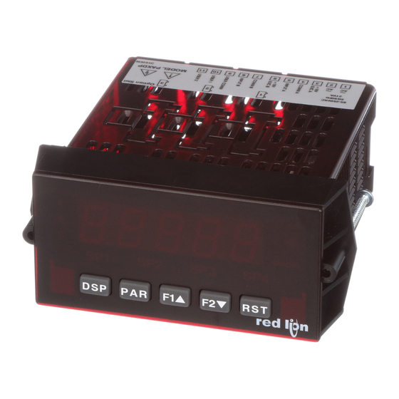
MODEL PAXDP – 1/8 DIN DUAL PROCESS INPUT METER
U L
C
US LISTED
R
IND. CONT. EQ.
51EB
GENERAL DESCRIPTION
The PAXDP Dual Process Input Meter offers many features and performance
capabilities to suit a wide range of industrial applications. Available in two
models, AC or DC power, the meter has the capability to accept two, 4 to 20 mA
or 0 to 10 VDC input signals. Each input signal can be independently scaled and
displayed. In addition, a math function can be performed on the two signals, C +
A + B, C - A - B, C + A - B, AB / C, CA / B, or C (A / B - 1). Any of the three
meter values can have Alarms, Comms, and/or a Retransmitted Analog Output
capability by simply adding optional cards. The optional plug-in output cards
allow the opportunity to configure the meter for current applications, while
providing easy upgrades for future needs.
The update rate of the meter is user selectable. This will help in those
applications where a quick response from the meter is of the utmost importance.
The rate can be adjusted from eight selections with a minimum of 5 updates/
second to a maximum of 105 updates/second.
The meters employ a bright 0.56" (14.2 mm) red sunlight readable LED
display. The intensity of display can be adjusted from dark room applications up
to sunlight readable, making it ideal for viewing in bright light applications.
The meters provide a MAX and MIN reading memory with programmable
capture time. The capture time is used to prevent detection of false max or min
readings which may occur during start-up or unusual process events.
The signal totalizer (integrator) can be used to compute a time-input product.
This can be used to provide a readout of totalized flow, calculate service intervals
of motors or pumps, etc. The totalizer can also accumulate batch operations.
The meter has four setpoint outputs, implemented on Plug-in option cards.
The Plug-in cards provide dual FORM-C relays (5A), quad FORM-A (3A), or
either quad sinking or quad sourcing open collector logic outputs. The setpoint
alarms can be configured to suit a variety of control and alarm requirements.
Communication and Bus Capabilities are also available as option cards. The
standard output is in Modbus Protocol. Any of the following option cards,
RS232, RS485, DeviceNet, or Profibus can be used with the meter. Readout
DIMENSIONS In inches (mm)
A
8. 8 . 8 . 8 . 8
B
C
SP
1
SP
2
S
P
3
S
P4
DSP
PAR
F1
F2
RST
3.80
(96.5)
Note: Recommended minimum clearance (behind the panel) for mounting clip installation is
V
1.95
(49.5)
.10
(2.5)
ACCEPTS TWO 4 - 20 mA OR 0 - 10 VDC INPUT SIGNALS
PROGRAMMABLE A/D CONVERSION RATE, 5 TO 105
READINGS PER SECOND
5-DIGIT 0.56" RED SUNLIGHT READABLE DISPLAY
VARIABLE INTENSITY DISPLAY
LINEARIZATION/SQUARE ROOT EXTRACTION INPUT RANGE
PROGRAMMABLE FUNCTION KEYS/USER INPUTS
9 DIGIT TOTALIZER (INTEGRATOR) WITH BATCHING
OPTIONAL CUSTOM UNITS OVERLAY W/BACKLIGHT
FOUR SETPOINT ALARM OUTPUTS (W/OPTION CARD)
COMMUNICATION AND BUS CAPABILITIES (W/OPTION CARD)
RETRANSMITTED ANALOG OUTPUT (W/OPTION CARD)
NEMA 4X/IP65 SEALED FRONT BEZEL
PC SOFTWARE AVAILABLE FOR METER CONFIGURATION
values and setpoint alarm values can be controlled through the bus. Additionally,
the meters have a feature that allows a remote computer to directly control the
outputs of the meter.
A linear DC output signal is available as an optional Plug-in card. The card
provides either 20 mA or 10 V signals. The output can be scaled independent of
the input range and can track either the input, totalizer, max/min readings, or
math calculation value.
Once the meters have been initially configured, the parameter list may be
locked out from further modification in its entirety or only the setpoint values
can be made accessible.
The meters have been specifically designed for harsh industrial environments.
With NEMA 4X/IP65 sealed bezel and extensive testing of noise effects to CE
requirements, the meter provides a tough yet reliable application solution.
SAFETY SUMMARY
All safety related regulations, local codes and instructions that appear in this
literature or on equipment must be observed to ensure personal safety and to
prevent damage to either the instrument or equipment connected to it. If
equipment is used in a manner not specified by the manufacturer, the protection
provided by the equipment may be impaired.
Do not use this unit to directly command motors, valves, or other actuators
not equipped with safeguards. To do so can be potentially harmful to persons or
equipment in the event of a fault to the unit.
CAUTION: Risk of Danger.
Read complete instructions prior to
installation and operation of the unit.
2.1" (53.4) H x 5.0" (127) W.
(44.5)
4.10
(104.1)
1
CAUTION: Risk of electric shock.
12
16
13
17
14
18
1.75
15
19
1 2 3 4
5 6
7
8 9 10 11
3.60 (91.4)
Bulletin No. PAXDP-K
Drawing No. LP0578
Released 11/12
20
21
22
1.75
23
(44.5)
24
25
Advertisement
Table of Contents

Related Manuals for red lion PAXDP


Summary of Contents for red lion PAXDP
- Page 1 Additionally, the meters have a feature that allows a remote computer to directly control the The PAXDP Dual Process Input Meter offers many features and performance outputs of the meter.
-
Page 2: Table Of Contents
able OnTenTs Ordering Information ....2 Wiring the Meter ..... . . 6 General Meter Specifications . -
Page 3: General Meter Specifications
eneral eTer peCifiCaTiOns 1. DISPLAY: 5 digit, 0.56" (14.2 mm) variable intensity red sunlight readable 10. LOW FREQUENCY NOISE REJECTION: (-19999 to 99999) Normal Mode: (digital filter off) 2. POWER: INPUT UPDATE RATE 50 Hz ±1 Hz 60 Hz ±1 Hz AC Versions: >90 dB >65 dB... -
Page 4: Accessories
PAXDP meter easier and allows the user Baud Rate: 38400 to save the PAXDP database in a PC file for future use. The software is available Data Bit: 8 as a free download from Red Lion’s website. -
Page 5: Installing The Meter
These jumpers are used to select the proper input types, Voltage (V) or Current (I). The input type selected in programming must match the jumper setting. See the Jumper Selection Figures for more details. PAXDP Jumper Selection JUMPER SELECTIONS indicates factory setting. -
Page 6: Installing Plug-In Cards
3.0 i nsTalling ards To Install: The plug-in cards are separately purchased optional cards that perform specific functions. These cards plug into the main circuit board of the meter. The 1. With the meter removed from the case, locate the plug-in card connector for plug-in cards have many unique functions when used with the PAX. - Page 7 4.1 POWER WIRING AC Power DC Power Terminal 1: VAC Terminal 1: +VDC Terminal 2: VAC Terminal 2: -VDC 4.2 INPUT SIGNAL WIRING Before connecting signal wires, the Input Range Jumper must be verified for proper position. INPUT A SIGNAL WIRING Voltage Signal Current Signal Current Signal (2 wire...
-
Page 8: Reviewing The Front Buttons And Display
4.3 USER INPUT WIRING Before connecting the wires, the User Input Logic Jumper should be verified for proper position. If not using User Inputs, then skip this section. Only the appropriate User Input terminal has to be wired. Sinking Logic Sourcing Logic Terminal 9: Terminal 9: -VDC thru external switching device... -
Page 9: Programming The Meter
6.0 p rOgramming The eTer OVERVIEW DISPLAY MODE PROGRAMMING MENU Display User Input/ Assignment/ Signal Function Program Secondary Totalizer Setpoint* Serial* Analog* Factory Signal Input B Lock-out Function (Integrator) (Alarm) Communication Output Service Input A Parameters Parameters Parameters Parameters Parameters Parameters Parameters Operations... - Page 10 The PAXDP can apply the square root function directly to the sensor signal by selecting the Square Root Extraction Input Range ( ). When ...
- Page 11 INPUT VALUE FOR SCALING POINT 1 DISPLAY VALUE FOR SCALING POINT 2* Enter the second coordinating Display Value by using the arrow keys. This For Key-in ( ), enter the known first Input Value by using the arrow keys.
- Page 12 INPUT A ZERO (TARE) DISPLAY HOLD ALL FUNCTIONS The meter disables processing the input, holds all display contents, and locks the state of all outputs as long as activated (maintained action). The serial port continues data transfer. ...
- Page 13 CHANGE DISPLAY INTENSITY LEVEL RESET MINIMUM When activated (momentary action), the display intensity changes to the next When activated (momentary action), flashes and the Minimum reading ...
- Page 14 6.3 mOdule 3 - d isplay ssignmenT and rOgram arameTers PARAMETER MENU 3-LOC INP A INP b CALC SP-1 SP-2 SP-3 SP-4 COdE Input A Input B Calculation Max Display Min Display Total Display Setpoint 1 Setpoint 2 Setpoint 3 Setpoint 4 Security Assignment...
- Page 15 6.4 mOdule 4 - s eCOndary unCTiOn arameTers PARAMETER MENU 4-SEC OFS-A OFS-b HI-AS HI-t LO-AS LO-t dSP-t Input A Input B Max Capture Max Capture Min Capture Min Capture Display Update Offset Value Offset Value Assignment Delay Time Assignment Delay Time Rate...
- Page 16 CALCULATION FILTER SETTING CALCULATION CONSTANT VALUE The constant value is used in the Calculation Function formulas to provide The calculation filter setting is a time constant expressed in tenths of a offsetting or scaling capabilities.
- Page 17 6.5 mOdule 5 - T OTalizer nTegraTOr arameTers 5-tOt 5-tOt PARAMETER MENU ASIN dECPt dECPt tbASE SCFAC Locut P-uP Totalizer Totalizer Totalizer Totalizer Totalizer Low Totalizer Power Assignment Decimal Point Time Base Scale Factor Cut Value Up Reset The totalizer accumulates (integrates) the relative Input value using one of TOTALIZER POWER UP RESET two modes.
- Page 18 See the Setpoint Alarm Figures in the Setpoint Card Bulletin for a visual detail of each action. The Inside Band action is shown here as it only applies to the PAXDP. No Setpoint Action ...
- Page 19 SP1 - (-SPn) SP1 + (-SPn) ALARM ALARM STATE STATE TRIGGER POINTS TRIGGER POINTS Deviation Low Acting (SP < 0)= Deviation High Acting (SP < 0) = SP1 + SPn SP1 + SPn SP1 - SPn SP1 - SPn ALARM ALARM STATE...
- Page 20 Since the Modbus protocol is included within the PAXDP, the PAX Modbus option card, PAXCDC4, should not be used. The PAXCDC1 (RS485), or PAXCDC2 (RS232) card Set the parity bit to match that of the other serial communications equipment should be used instead.
- Page 21 Following a transmit value (‘*’ terminator) or Modbus command, the - Enters the sub-menu to select the meter parameters to appear during a PAXDP will wait this minimum amount of time in seconds before issuing a print request. For each parameter in the sub-menu, select for that parameter ...
- Page 22 HEX < > values. Read and write functions can be performed in either Integers or Hex as long as the conversion was done correctly. Negative numbers are represented by two’s complement. Note: The PAXDP should not be powered down while parameters are being changed. Doing so may corrupt the non-volatile memory resulting in checksum errors. REGISTER...
- Page 23 REGISTER FACTORY REGISTER NAME LOW LIMIT HIGH LIMIT ACCESS COMMENTS SETTING ADDRESS FREQUENTLY USED REGISTERS (Continued) 40043 Alternate Setpoint 2 Value (Hi word) -19999 99999 Read/Write Setpoint List B 40044 Alternate Setpoint 2 Value (Lo word) 40045 Alternate Setpoint 3 Value (Hi word) -19999 99999 Read/Write...
- Page 24 Transmitting Data From the Meter Analog Output Register (AOR) ID: W Data is transmitted from the meter in response to either a transmit command This register stores the present signal value of the analog output. The range (T), a print block command (P) or User Function print request. The response of values of this register is 0 to 4095, which corresponds to the analog output from the meter is either a full field transmission or an abbreviated transmission.
- Page 25 (start bit of next byte). The receiver then continuously looks for the occurrence of the start bit. If 7 data bits and no parity is selected, then 2 stop bits are sent from the PAXDP.
- Page 26 6.8 mOdule 8 - a ) Ñ nalOg uTpuT arameTers PARAMETER MENU 8-Out tYPE ASIN AN-LO AN-HI Analog Analog Analog Low Analog High Analog Type Update Time Assignment Scale Value Scale Value Ñ - An analog output card must be installed in order to access this module.
-
Page 27: Factory Service Operations
6.9 mOdule 9 - f aCTOry erviCe peraTiOns PARAMETER MENU 9-FCS d-LEV COdE Display Factory Intensity Level Service Code ANALOG OUTPUT CARD CALIBRATION DISPLAY INTENSITY LEVEL Before starting, verify that the precision voltmeter (voltage output) or current Enter the desired Display Intensity Level (0-15) by ... -
Page 28: Troubleshooting Guide
ERROR CODE (Err xxx or EE xxx) PRESS: Reset KEY (If cannot clear contact factory.) For further assistance, contact technical support at the appropriate company numbers listed. PARAMETER VALUE CHART Programmer ________________ Date ________ PAXDP MODEL NUMBER ________ Meter# _____________ Security Code ________ Input Parameters Signal ... - Page 29 User Input and Function Key Parameters Totalizer (Integrator) Parameters FACTORY FACTORY DISPLAY PARAMETER USER SETTING DISPLAY PARAMETER USER SETTING SETTING SETTING TOTALIZER ASSIGNMENT USER INPUT 1 TOTALIZER DECIMAL POINT ...
-
Page 30: Programming Overview
QuiCK OvervieW... - Page 31 This page intentionally left blank...
- Page 32 The Company disclaims all liability for any affirmation, promise or representation with respect to the products. The customer agrees to hold Red Lion Controls harmless from, defend, and indemnify RLC against damages, claims, and expenses arising out of subsequent sales of RLC products or products...
Need help?
Do you have a question about the PAXDP and is the answer not in the manual?
Questions and answers