
Related Manuals for Eaton MMX34AA012F0-0


Summarization of Contents
About this Manual
Writing Conventions
Explains conventions used in the manual for clarity and understanding.
Abbreviations and Symbols
Lists symbols and abbreviations used throughout the manual for reference.
M-Max Series Overview
Notes on the Second MMX Upgrade
Details extended functionality of MMX inverters from a specific production date.
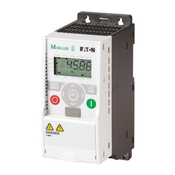
M-Max Frequency Converter
Introduces the M-Max frequency converter and its function.
Control Signal Terminals and Microswitches
Illustrates and labels control signal terminals and microswitches.
Component Identification
Identifies and describes the components of the M-Max series.
Checking the Delivery
Provides instructions for verifying the contents and condition of the delivered product.
Scope of Supply
Lists the items included in the standard delivery package for the M-Max inverter.
Nameplate Rating Data
Explains how to interpret the rating data inscriptions on the device nameplate.
Catalog Number Selection
Details the type designation code and part number structure for M-Max series inverters.
Examples
Provides examples of M-Max series inverter part numbers and their meanings.
Technical Data and Specifications
Presents detailed technical specifications and data for the M-Max series.
General Rated Operational Data
Lists general operational data, including power section and control section specifications.
Description of the M-Max
Provides an overview of the M-Max device, showing its main components.
Features
Highlights the key features and operational capabilities of the M-Max frequency inverter.
Selection Criteria
Outlines the criteria for selecting the appropriate frequency inverter for a given application.
Proper Use
Defines the intended industrial use of M-Max frequency inverters and prohibits other applications.
Maintenance and Inspection
Recommends regular checks and maintenance measures for ensuring inverter longevity.
Maintenance Measures and Intervals
Lists specific maintenance tasks and their recommended intervals for the M-Max inverters.
Storage
Provides guidelines for proper storage conditions to maintain inverter integrity.
Charging DC Link Capacitors
Explains the procedure for controlled recharging of DC link capacitors after long storage.
Service and Warranty
Provides contact information for support and warranty claims related to M-Max frequency inverters.
Safety
Dangerous Electrical Voltage!
Crucial warning about dangerous electrical voltage and essential safety precautions.
Before Commencing the Installation
Lists critical safety steps to follow before starting installation work.
Definitions and Symbols
Explains warning symbols and their associated meanings for hazard identification.
Warnings and Cautions
Provides important warnings and cautions related to safe operation and installation.
Engineering
Introduction
Introduces the engineering chapter and drive system planning considerations.
Drive System (PDS)
Describes the Power Drive System (PDS) components for project planning.
Electrical Power Network
Details input connection configuration and voltage/frequency considerations for electrical networks.
Input Voltage and Frequency
Specifies input voltage and frequency ranges and tolerances for energy suppliers.
Voltage Balance
Discusses voltage balance issues in AC power networks and potential solutions.
Total Harmonic Distortion (THD)
Explains THD as a measure of harmonic distortion in input variables.
Input Reactors
Describes the function of input reactors for limiting input feedback and reducing emissions.
Safety and Switching
Covers safety aspects related to fuses, cable cross-sections, and switching devices.
Fuses and Cable Cross-Sections
Provides guidance on selecting appropriate fuses and cable cross-sections.
Residual-Current Device (RCD)
Explains the purpose and type of RCDs required for frequency inverter protection.
Identification on the Residual-Current Circuit-Breakers
Highlights issues with RCDs and frequency inverters due to internal DC currents.
EMC Measures
Explains measures for achieving electromagnetic compatibility in drive systems and environments.
EMC Environment and Category
Defines EMC environments and categories for frequency controlled drives.
Motor and Application
Provides recommendations for motor selection and parallel motor connection.
Motor Selection
Offers general recommendations for selecting three-phase asynchronous motors.
Connecting Motors in Parallel
Details how to connect multiple motors in parallel to a frequency inverter's output.
Motor and Circuit Type
Explains motor connection types (star/delta) and their relation to rating plates.
87-Hz Characteristic Curve
Describes the 87-Hz characteristic curve for motors, considering thermal loading.
V/Hz-Characteristic Curve
Shows the allocation of frequency inverters based on input voltage and motor circuit type.
Bypass Operation
Explains how to enable operation of the motor directly from the input supply.
Bypass Motor Control (Example)
Provides an example wiring diagram for bypass motor control.
Connecting EX Motors
Gives notes on connecting explosion-protected motors, including installation location.
Sinusoidal Filter
Describes the function and benefits of sinusoidal filters connected in the output.
Installation
Installation Instructions
Gives instructions for installing M-Max series inverters, specifying IP ratings and accessories.
Mounting Position
Illustrates permissible mounting positions and angles for different frame sizes.
Cooling Measures
Details air-cooling requirements, clearance, and required cooling air for proper operation.
Air-Cooling Space
Specifies required clearances around the inverter for effective air circulation.
Minimum Clearance and Required Cooling Air
Provides a table of minimum clearances and cooling air volumes for different frame sizes.
Air-Baffle Due to Increased Circulation with Device Fan
Explains the need for air baffles when stacking devices vertically for proper airflow.
Fixing
Explains methods for mounting inverters using screws or mounting rails, including dimensions.
Fastening with Screws (FS1–FS5)
Details the procedure and specifications for fastening inverters using screws.
Mounting Dimensions
Provides a table with mounting dimensions, mass, and torque specifications for frame sizes.
Fastening on Mounting Rails (FS1–FS3)
Describes the alternative method of fastening inverters onto mounting rails conforming to IEC/EN 60715.
Mounting Rail Conforming with IEC/EN 60715
Illustrates the standard for mounting rails used for inverter installation.
Fastening to the Mounting Rail
Shows the steps for securely attaching the inverter to a mounting rail.
Dismantling from Mounting Rails
Explains the procedure for safely removing the inverter from a mounting rail.
Demounting
Provides a step-by-step guide for demounting the inverter using basic tools.
Cable Flange Plate (Accessories)
Describes the cable routing plate and brackets for arranging and fastening connection cables.
Mounting the Cable Routing Plate and the Brackets
Details the steps for installing the cable routing plate and associated brackets.
EMC Installation
Covers measures for achieving electromagnetic compatibility, including grounding and cable routing.
EMC Measures in the Control Panel
Specifies EMC measures for installation within control panels for optimal performance.
Earthing
Explains the importance and method of proper earthing for system safety and EMC.
Screen Earth Kit
Provides guidelines for effective cable shielding connections to minimize interference.
Electrical Installation
Provides essential safety warnings and guidelines for electrical installation procedures.
Connection to Power Section
Shows general connections for the frequency inverter in the power section and terminal designations.
Three-Phase Input Connection
Illustrates the three-phase input connection for MMX32, MMX34, and MMX35 models.
Terminal Designations in the Power Section
Lists and explains the terminal designations for power connections in the M-Max series.
Ground Connection
Details how to establish a proper ground connection using cable clamp plates.
Connection in Power Section
Shows detailed diagrams for connecting power terminals across different M-Max series models.
Stripping Lengths in the Power Section in inches (mm)
Provides a table specifying recommended stripping lengths for power section connections.
Screened Connection Cable
Recommends shielded, four-wire cables for motor connections to minimize current loads.
Connection with Twisted Cable Shielding
Explains the recommended method for connecting twisted cable shielding.
Four-Core Shielded Motor Supply Cable
Illustrates the construction of a recommended four-wire, shielded motor supply cable.
Arrangement and Connection of the Power Terminals
Details the arrangement and size of power terminals, including screw tightening torques.
Connection on Control Section
Describes the arrangement and connection of control signal terminals under the front cover.
Position of Control Signal Terminals
Illustrates the layout and mounting of control signal terminals on the frequency inverter.
Example for a Single-Side Connection (PES) to the Frequency Inverter
Provides an example of a single-side connection using PES for the frequency inverter.
Example for an Insulated End of the Control Cable
Illustrates an example of an insulated end for a control cable connection.
Prevent the Shield from Becoming Unbraided
Offers methods to prevent shield unbraiding for EMC compliance.
Operation
Commissioning Checklist
A checklist to ensure proper installation and wiring before placing the frequency converter into operation.
Operational Hazard Warnings
Highlights critical warnings and cautions for safe operation and commissioning.
Commissioning with Control Signal Terminals (Factory Setting)
Explains how to perform simple commissioning using factory default settings and control signal terminals.
Circuit Example
Shows a simplified connection example for basic commissioning with default settings.
Operational Data Indicator (Operational)
Describes how to select and view operational data indicators on the LCD display.
Operation (RUN) via Control Signal Terminal (I/O) with Left Rotating Field (REV)
Details operating the inverter via control signal terminals with left rotating field (REV).
Start-Stop Command with Maximum Setpoint Value Voltage, Acceleration Ramp 3s
Explains start-stop commands and acceleration ramp settings for motor operation.
Brief Instructions
Provides concise, step-by-step instructions for starting the motor.
Error and Warning Messages
Error Messages
Explains how faults are displayed, their causes, and how to acknowledge them.
Example of an Error Message (Undervoltage)
Shows an example of an undervoltage error message display.
Acknowledge Fault Message (Reset)
Describes methods for acknowledging and resetting error messages, including automatic restart.
Alarm Messages
Explains warning messages, their display, and their impact on operation.
Example of an Alarm Message
Illustrates an example of an alarm message display.
Fault Log (FLT)
Explains how to access and view the last nine faults recorded in the fault log.
List of Fault Messages (F) and Warning Messages (AL)
A comprehensive list of fault and alarm codes with their possible causes and instructions.
Parameters
Control Unit
Details the elements of the M-Max integrated control unit, including keypad and display.
View of the Keypad with LCD Display, Function Keys and Interface
Shows the integrated control unit keypad layout, function keys, and LCD display.
Setting Parameters
Guides through the process of selecting and setting parameters, including the Quickstart Wizard.
Parameter Menu (PAR)
Explains how to access and navigate the parameter menu for configuration.
Parameter Menu (P1.1 = 1, Quick Configuration)
Describes the guided quick configuration process using parameter P1.1.
Schematic Representation of Parameter Access
Provides a visual overview of accessing parameters via the Quickstart Wizard or free selection.
Quick Start Parameter Guide
Provides preset application parameters for quick configuration and basic setup.
Predefined Application Parameters from Parameter P1.2
Lists predefined parameter values for different applications like Pump, Fan, and High Load.
Analog Input (P2)
Details how to adapt analog inputs for setpoint values and process variables.
Analog Inputs AI1 and AI2
Explains the function and connection of analog inputs AI1 and AI2.
Scaled Value Range (AI1, AI2)
Illustrates examples of scaled analog input signal ranges and their characteristics.
Example of Scaled Analog Input Signals
Shows examples of scaled analog input signals without offset.
Example of Scaled Analog Input Signals with Offset
Shows examples of scaled analog input signals with an offset.
Digital Inputs (P3)
Explains how to set the operation and function of digital inputs for various control logic.
Digital Inputs for Source and Sink Type
Illustrates digital inputs for source and sink types and their logic.
Control Logic Reaction to a Rising or Falling Edge
Describes the control logic reaction to rising or falling edges for digital inputs.
Digital Inputs
Lists parameters for configuring digital input functions like start/stop and fixed frequencies.
Analog Outputs (P4)
Details the analog voltage signal output (0-10V) and its factory settings.
Analog Output AO (Connection Examples)
Provides connection examples for the analog output AO.
Analog Outputs
Lists parameters for configuring analog output signals and their settings.
Digital Outputs (P5)
Describes the different digital output configurations and their assignments.
Digital Outputs
Lists parameters for configuring digital outputs, including relay and transistor types.
Drives Control (P6)
Covers parameters for defining operating conditions and control sources for the frequency inverter.
Example: Control Level I/O Activated
Illustrates the display when the I/O control level is activated.
Acceleration and Deceleration Time
Explains how to set acceleration and deceleration times for frequency setpoint changes.
S-Formed Curve for Acceleration and Deceleration Ramps
Illustrates the S-formed curve for acceleration and deceleration ramps.
Automatic Restart After Error Message (Two Start Attempts)
Details parameters for automatic restart after error messages and testing periods.
Motor (P7)
Details how to enter motor ratings plate information for optimal operation.
Motor Parameters from Ratings Plate
Explains how to set motor parameters based on the rating plate for accurate control.
Switching Type for Motor Stator Windings
Discusses the dependency of switching type on input voltage for motor stator windings.
Circuits (Delta, Star)
Illustrates delta and star connection circuits for three-phase motors.
Protective Functions (P8)
Explains how to set reactions to external influences and enhance drive system protection.
Analog minimum reference error (live-zero)
Monitors the live zero of analog inputs and triggers warnings or faults.
Undervoltage error
Detects under-voltage errors in the intermediate circuit and triggers alarms or faults.
Ground fault
Monitors ground faults by checking motor phase currents for protection.
Stall protection
Protects the motor from brief overloads by monitoring current and frequency.
Underload protection
Monitors motor load to detect issues like torn drive belts or dry running pumps.
Motor, temperature protection
Protects the motor from overheating using a temperature algorithm based on motor current.
Motor, ambient temperature
Allows setting the ambient temperature for motor protection calculations.
Motor, cooling factor at zero frequency
Defines the motor cooling factor at zero frequency relative to rated frequency cooling.
Motor Heat Protection (P8.6–P8.9)
Configures motor temperature protection based on a calculated model and motor current.
Motor Cooling Power
Illustrates the motor cooling power curve as a function of frequency.
Calculation of Motor Temperature
Explains the calculation of motor temperature using time constants and current.
PID Controller (P9)
Describes the PID controller setup for drive control and external applications.
PID Controller
Explains the PID controller function and its parameters for process control.
PID controllers, P gain
Allows setting the Proportional Gain (KP) for the PID controller's control action.
PID controller, I reset time
Sets the Integral Time Constant for the PID controller's response.
PID controller, setpoint, keypad reference
Defines the setpoint range for keypad reference input to the PID controller.
PID controller, setpoint source
Allows selection of the setpoint source for the PID controller (Keypad, Fieldbus, AI1, AI2).
PID controller, process variable (PV) source
Specifies the source for the process variable (actual value) for the PID controller.
PID controller, actual value limiting, minimum
Sets the minimum limit value for scaling the actual process variable.
PID controller, actual value limiting, maximum
Sets the maximum limit value for scaling the actual process variable.
PID controller, controller deviation
Configures controller deviation monitoring and inverted PID control.
PID controller, D rate time
Sets the differential time constant for the PID controller.
PID controller, output filter, delay time
Sets the delay time for the output filter of the PID controller.
Sleep mode, frequency
Defines the frequency threshold below which the inverter enters sleep mode.
Sleep mode, wake up setpoint
Sets the wake-up setpoint value for restoring RUN mode from sleep.
Sleep mode, delay time
Determines the minimum period the inverter stays below the sleep frequency.
PID Controller, Actual Value Message FBV
Explains the Feedback Value Check signal for monitoring actual value limits.
Block Diagram, Ventilation with “Two-Stage Control”
Illustrates a block diagram for a two-stage control ventilation system.
Fixed Frequency Setpoint Value (P10)
Explains how to set fixed frequencies and sequence control for cyclical program execution.
Fixed Frequency
Details how to set eight different fixed frequency setpoints (FF0 to FF7).
Fixed Frequencies FF1, FF2 and FF3 (= FF1 + FF2)
Shows factory settings for FF1, FF2, and FF3, activated via digital inputs DI3 and DI4.
Example: Activation of the Fixed Frequencies in the Factory Setting with Acceleration and Deceleration Ramps
Illustrates activation of fixed frequencies with factory acceleration and deceleration ramps.
Sequence Control
Enables cyclical program sequences with fixed frequency setpoints and operating modes.
V/Hz-Characteristic Curve (P11)
Details the V/Hz characteristic curve settings for controlling motor voltage and frequency.
V/Hz-Characteristic Curve
Shows different V/Hz characteristic curve types: Linear, Squared, and Configurable.
V/Hz-Characteristic Curve, continued
Provides further details on V/Hz characteristic curves, including cut-off frequency.
Carrier frequency
Allows setting the carrier frequency to reduce motor noise and improve speed stability.
Sine-wave filter (constant carrier frequency)
Enables a sine-wave filter for reducing losses and noise, requiring constant carrier frequency.
Braking (P12)
Covers different braking functions like DC braking and regenerative braking.
DC Braking
Explains how DC braking works by supplying DC current to the motor stator winding.
Braking Time at Start
Sets the duration for DC braking activation when a start command is given.
DC braking, start frequency
Activates DC braking after a stop command based on the output frequency.
Start Frequency During Relay Ramp
Illustrates the start frequency during relay ramp for DC braking activation.
DC braking, braking time at STOP
Sets the duration for DC braking after a stop command.
Braking Time in Case of Stopping
Shows how braking time is affected by output frequency and stop conditions.
Regenerative Braking
Explains how regenerative energy increases DC link voltage and enables braking torque.
Regenerative Braking with External Braking Resistor
Details using an external resistor with the brake chopper for higher braking torque.
Brake chopper
Covers the activation of the brake chopper function for dissipating excess brake energy.
Brake chopper, DC bus switching threshold
Sets the switching threshold for the brake transistor based on DC link voltage.
Mechanical Brake (Actuation)
Describes implementing external mechanical brake actuation via digital outputs.
Braking, continued
Covers parameters related to external brake activation and thresholds.
External brake, delay time opening
Sets the delay time for opening the external brake after a start enable.
External brake, frequency threshold opening
Activates the external brake when the frequency exceeds a set threshold.
External brake, frequency threshold closing
Activates the external brake when the frequency drops below a set threshold.
External brake, frequency threshold REV closing
Activates the external brake for reverse rotation when frequency drops below a threshold.
External brake, current limit, opening
Activates the external brake when the current limit reaches a set value.
Logic Function (P13)
Explains how to link parameters logically and assign results to digital outputs.
Logic Linking of A and B
Illustrates logic linking of parameters P13.1 (A) and P13.2 (B).
Example: Digital output RO1 (N/O contact R13/R14) is required to indicate during operation that the set current limit has been reached
Example showing RO1 output indicating when the set current limit is reached.
Logic Function, Selection input A
Allows selection of input A for logic functions, defining its role.
Logic Function, Selection input B
Allows selection of input B for logic functions, defining its role.
Logic Function, select operation
Defines the logical operation (AND, OR, XOR) for selected functions of inputs A and B.
Second Parameter Set (P14)
Allows alternative operation of two motors with different rating specifications.
Second Parameter Set
Combines parameters for a second motor, enabling alternative operation.
Motor rated current (2PS)
Sets the rated operational current for the second motor.
Current limit (2PS)
Sets the current limit for the second motor.
Motor rated speed (2PS)
Sets the rated speed in RPM for the second motor.
Motor power factor (cos ) (2PS)
Sets the power factor for the second motor.
Motor rated operating voltage (2PS)
Sets the rated operating voltage for the second motor.
Motor nominal frequency (2PS)
Sets the nominal frequency for the second motor.
Minimum frequency (2PS)
Sets the minimum frequency for the second motor.
Maximum frequency (2PS)
Sets the maximum frequency for the second motor.
Acceleration time (2PS) (acc3)
Sets the acceleration time for the second parameter set.
Deceleration time (2PS) (dec3)
Sets the deceleration time for the second parameter set.
V/Hz characteristic curve (2PS)
Configures the V/Hz characteristic curve for the second parameter set.
Torque increase (2PS)
Enables automatic output voltage increase for the second parameter set.
Motor temperature protection (2PS)
Sets motor temperature protection for the second parameter set.
Motor ambient temperature (2PS)
Allows setting the ambient temperature for the second motor's protection.
Motor cooling factor at zero frequency (2PS)
Defines the cooling factor at zero frequency for the second motor.
Motor thermal time constant (2PS)
Sets the thermal time constant for the second motor.
Example 1
Presents an example application of the second parameter set for roller conveyor.
Roller conveyor with rotary table
Details a roller conveyor application using two motors and the second parameter set.
Example 2
Illustrates an example of using two different deceleration times for the stop function.
Stop function with two different deceleration times
Explains how to activate different deceleration times using the second parameter set.
Appendix A
Special Technical Data
Provides detailed technical data for M-Max frequency inverters across different power classes.
Device Series MMX11
Lists technical data specific to the MMX11 device series.
Device Series MMX12
Lists technical data specific to the MMX12 device series.
Device Series MMX32
Lists technical data specific to the MMX32 device series.
Device Series MMX34
Lists technical data specific to the MMX34 device series.
Device Series MMX35
Lists technical data specific to the MMX35 device series.
Dimensions and Frame Sizes
Provides approximate dimensions and frame sizes for different inverter models.
Dimensions and Frame Sizes, FS1–FS3 (FS = Frame Size)
Shows dimensions for frame sizes FS1, FS2, and FS3.
Dimensions and Frame Sizes, FS4 and FS5 (FS = Frame Size)
Shows dimensions for frame sizes FS4 and FS5.
PC Interface Card
Details the MMX-COM-PC connection module for PC communication.
MMX-COM-PC
Describes the MMX-COM-PC connection module for PC communication.
Equipment Supplied MMX-COM-PC
Lists the components included with the MMX-COM-PC kit.
Fitting the MMX-COM-PC Connection Module
Details the steps for fitting the MMX-COM-PC connection module.
Removing the MMX-COM-PC Connection Module
Explains how to remove the MMX-COM-PC connection module.
Mounting Frame for Fieldbus Connection
Explains the MMX-NET-XA mounting frame for fieldbus interface cards.
MMX-NET-XA
Describes the MMX-NET-XA mounting frame for fieldbus connections.
MMX-NET-XA Mounting Frame
Details the MMX-NET-XA mounting frame components and installation.
Removing the Interface Cover on the MMX
Shows how to remove the interface cover on the MMX for mounting the frame.
MMX-NET-XB
Describes the MMX-NET-XB interface module for frame sizes FS4 and FS5.
MMX-NET-XB Interface Module
Details the MMX-NET-XB interface module for flush mounting fieldbus cards.
Remove Cover (FS4, FS5)
Explains how to remove the cover from FS4 and FS5 inverter models.
Plastic Bridge for Holding the Control Terminals
Provides a plastic bridge for holding control terminals, e.g., OPTE3 XMX-NET-PS-A.
Connecting the MMX-NET-XB Interface Module with the Fieldbus Interface Cards
Details connecting the MMX-NET-XB module with fieldbus interface cards.
PROFIBUS DP Fieldbus Interface Card
Provides information on PROFIBUS DP interface cards for M-Max series connection.
XMX-NET-PD-A PROFIBUS DP Fieldbus Interface Card with Nine-Pole Sub-D Plug Connection
Describes the PROFIBUS DP interface card with a nine-pole Sub-D plug connector.
XMX-NET-PS-A
Describes the PROFIBUS DP interface card with a five-pole screw terminal.
Fieldbus Connection
Illustrates the fieldbus connection implementation for interface cards.
XMX-NET-DN-A DeviceNet Fieldbus Interface Card
Provides information on the DeviceNet fieldbus interface card for M-Max series.
Cables, Fuses and Disconnect Devices
Covers cable cross-sections, fuses, and disconnect devices requirements.
Specified Fuses and Disconnect Devices
Lists specified fuses and disconnect devices based on part number and voltage.
List of Parameters
An index of parameters with their PNU ID, access, and page number.
Quick Start Parameter Guide
A guide to parameters for quick configuration and application settings.
System Parameters in the Quick Start
Lists system parameters that inform the user of device-specific settings.
Communication
Details communication settings including RS485 interface parameters.
Information on Interface RS485 (Control Signal Terminals A, B)
Details communication status, fieldbus protocol, slave address, and baud rate for RS485 interface.
Default I/O
Shows the default assignments for digital inputs and outputs.
Digital Input
Lists parameters for configuring digital input functions.
Analog Output
Lists parameters for configuring analog output signals.
Digital Output, continued
Continues the list of parameters for digital output configurations.
Drives Control
Covers parameters for defining operating conditions and control sources.
Appendix B
Door Panel Keypad Adapter System—Mounting Instructions
Provides instructions for installing the door panel keypad adapter system.
Overview
Gives an overview of the door keypad's purpose and installation requirements.
Door Keypad Mounting Kit
Lists the components included in the door keypad mounting kit.
Door Keypad Components
Identifies and describes each component of the door keypad mounting kit.
Mounting Procedure
Provides step-by-step instructions for mounting the door keypad.
Door Keypad Mounting Instructions
Details the mounting procedure for the door keypad on a cabinet door.
Door Keypad Mounting Instructions, continued
Continues the mounting instructions, covering grounding cable and adapter assembly.
Dimensions
Provides approximate dimensions for the door keypad and its cut-out.
Door Keypad Cut-out Dimensions
Shows the precise dimensions for cutting out the panel for door keypad installation.
Door Keypad Dimensions
Illustrates the front and side view dimensions of the door keypad.
Need help?
Do you have a question about the MMX34AA012F0-0 and is the answer not in the manual?
Questions and answers