
Subscribe to Our Youtube Channel
Related Manuals for Eaton ETN1000


Summary of Contents for Eaton ETN1000
- Page 1 EATON ETN1000 / ETN2000 Grid PV-Inverter Installation and Operation Manual Version 1.6 E 2010.06...
-
Page 2: Table Of Contents
Before you start…....................3 Safety instructions ....................4 Limited Warranty..................... 6 Overview......................7 Features......................8 Installation instructions................. 9 Opening the package ................9 Before installation ..................9 Mounting Inverter to the wall ..............11 Connecting to the grid (AC utility)............14 Connect to PV Panel (DC input)............. - Page 3 Front Panel ..................... 20 LCD Display Sequence: ................. 22 Maximum Power Point Tracking (MPPT) ..........22 Maximum Power Point Tracking (MPPT) ..........23 6. Inverter Status....................24 Display information ................. 24 7. Communications....................27 8. Trouble shooting....................29 9. Specifications....................31 Electrical ....................
-
Page 4: Before You Start
Before you start… Congratulations on choosing EATON ETN1000 / ETN2000 Grid PV-Inverter, a product from EATON Grid PV-Inverter is a highly reliable product due to its innovative design and perfect quality control. Such an inverter is used in high demand, grid-linked PV systems. -
Page 5: Safety Instructions
Safety instructions Risk of Electric Shock 1. Do not remove the casing. Inverter contains no user serviceable parts. Refer servicing to qualified service personnel. 2. When a photovoltaic panel is exposed to light, it generates a DC voltage. When connected to this equipment, a photovoltaic panel will charge the DC link capacitors. - Page 6 Hot surfaces Although designed to meet all safety requirements, some parts and surfaces of Inverter are still hot during operation. To reduce the risk of injury, do not touch the heat sink at the back of the PV-Inverter or nearby surfaces while Inverter is operating.
-
Page 7: Limited Warranty
The right to repair and/or replace the unit is at the manufacturers’ discretion. Any damages discovered during installation should be submitted via a written damage report within 5 working days of receiving the PV-Inverter. Otherwise EATON is not responsible for damages beyond the scope of this warranty. Edition 1.6E, 2010/06... -
Page 8: Overview
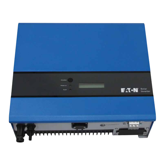
1. Overview 1.0 kW / 2.0kW Design Overview Front View Bottom View Parts Description Display information switch Operation LED, Green , normal Operation LED, Red, fault status Solar panel input LCD Display: Showing the inverter status RS232 cover Utility (AC) connection: Terminal Black Optional communications slot: RS232 &... -
Page 9: Features
2. Features Very high conversion efficiency (up to 96%) MPPT (Maximum Power Point Tracking) Higher power capacity than similar products of the same size. Embedded LCD display showing complete status information Natural convection cooling. Quiet, fan-less design Stylish, modern casing Compact, small profile High reliability, and Easy to install Maintenance free... -
Page 10: Installation Instructions
3. Installation instructions Opening the package After opening the package, please check the contents of the box. It should contain the following: One Inverter One Instruction manual One mounting frame 4 mounting screws 2 safety-lock screws One cable gland and TB cover for AC cable Before installation Before starting installation please consider the following items: Check the ambient temperature of installation is within specified... - Page 11 ° ° ° ° Edition 1.6E, 2010/06...
-
Page 12: Mounting Inverter To The Wall
Mounting Inverter to the wall Select a wall or solid vertical surface that can support the PV-Inverter. Inverter requires adequate cooling space. Allow at least 20cm space above and below the inverter. Using the mounting frame as a template, drill 4 holes as illustrated in the following figures. - Page 13 Hang the inverter on the mounting frame Check the installation conditions a) Do not install the PV-Inverter on a slanted surface Edition 1.6E, 2010/06...
- Page 14 b) Check the upper straps of PV-Inverter and ensure it fits on to the bracket c) Insert safety-lock screws to the bottom leg to secure the inverter...
-
Page 15: Connecting To The Grid (Ac Utility)
Connecting to the grid (AC utility) Measure grid (utility) voltage and frequency. It should be 230VAC (or 220VAC), 50/60Hz, and single phase. Open the breaker or fuse between PV-Inverter and utility. For Inverter, connect AC wires as follows: Insert utility wires through cable gland. Connect wires according to polarities indicated on terminal block. -
Page 16: Connect To Pv Panel (Dc Input)
Twist the gland, attached screws in order to seal the AC gland cover. Suggested cable width for AC wire. Diameter φ Model Area (mm AWG no. (mm) EATON ETN1000 ≥1.02 ≥1.25 ≤16 EATON ETN2000 Connect to PV Panel (DC input) Make sure the maximum open circuit voltage (V... -
Page 17: Checking
in 2.0kW. ’ ’ Checking When the PV panels are connected and their output voltage is greater than 100 V but the AC grid is not yet connected, the message on the LCD display produce the following messages in order: “MODEL” -> “Waiting”... -
Page 18: System Diagram
PV panel PV Panel: Provide DC power to inverter. EATON ETN1000 / ETN2000 PV Inverter converts DC (Direct Current) power from PV panel(s) to AC (Alternating Current) power. Because Inverter is grid-connected it controls the current amplitude according to the PV Panel power supply. -
Page 19: Operating Your Pv-Inverter
5. Operating Your PV-Inverter Modes of operation There are 3 different modes of operation. 1. Normal mode: In this mode, Inverter works normally. Whenever the supplied power from PV panel is sufficient (voltage>150VDC), Inverter converts power to the grid as generated by the PV panel. If the power is insufficient, (voltage<100VDC) Inverter enters a “waiting”... -
Page 20: Front Panel Arrangement
Front Panel arrangement Function Key LCD (Liquid Crystal Display) Power-on LED Fault LED There are 2 LED’s on Inverter, one is green and the other is red. Normally, only the green LED switches on during operation. Their indicated status is explained as follows: Power on (green LED): It lights to indicate that Inverter is running. -
Page 21: Front Panel
Front Panel Operating Inverter is quite easy. During normal operation, Inverter runs automatically. However, to achieve maximum conversion efficiency of Inverter, please read through the following information: Automatic ON-OFF: Inverter starts up automatically when DC-power from the PV panel is sufficient. Once the PV-Inverter starts it enters one of the following 3 states: Standby: The PV string can only provide just enough voltage to minimum requirements of the controller. - Page 22 Repeatedly press the function key until the desired display is reached. Release the key and press again for more than 2 second until you see “Lock”, release the key; the information remains on the display. To change the display again, please press the key as indicated in above section 3.
-
Page 23: Lcd Display Sequence
LCD Display Sequence: Model name Feeding Pac =xxxx.xW Model Daily energy FW version A1.00 Etoday=xxx.xxKWh Total energy Operating status Normal state Eac=xxxxxxkWh DC-PV voltage Contrast Adj. Vdc=xxx.xV Contrast Feeding current Set language Iac= x.xA Set language AC-Grid freq. Frequency=xx.xHz AC-Grid voltage Vac=xxx.xV Edition 1.6E, 2010/06... -
Page 24: Maximum Power Point Tracking (Mppt)
Maximum Power Point Tracking (MPPT) A good PV inverter must be Maximum power point 1000W/m @ 1000W/m ~ 120W able to convert the maximum 800W/m power from any PV panel. Due 600W/m to its advanced design, Inverter PV-Inverter can track the maximum power from your PV panel in any condition. -
Page 25: Inverter Status
6. Inverter Status Inverter is designed to be user-friendly. Therefore, the status of the Inverter can be easily understood by reading the information that shown on the front panel display. All possible messages are shown in the following table. Display information Operating conditions In English Description... -
Page 26: Operating Conditions
Operating conditions In English Description Feeding current Iac = x.xA Feeding current amount in xx.x A PV array voltage Vdc = xxx.x V Input voltage from PV array, xxx.x VDC Etoday=xxx.xxKW Daily Energy The accumulated kWh of that day System Fault Earth fault of the PV-panels or failure of Isolation failure Isolation fault... - Page 27 Output DC sensor abnormal DC Sensor Fault Detection of DC output sensor is abnormal GFCI detection problem GFCI Failure The GFCI detection circuit is abnormal System Information EATON ETN1000 Model display Inverter model, xkW inverter /ETN2000 LCD contrast Contrast LCD contrast setting...
-
Page 28: Communications
The RS485 card can be used to work with Inverter’s EZ logger as multiple monitoring applications. Firmware upgrade: To up-to-date keep the firmware, use the RS232 port and supplied program to upgrade firmware. To do this, please contact EATON Customer Service. - Page 29 EATON Contact Information Telephone: 1300 3 EATON Web: http://www.Eatonelectric.com.au/ Edition 1.6E, 2010/06...
-
Page 30: Trouble Shooting
2. If PV voltage is less than 450VDC, and the problem still occurs, please contact Eaton. 1. Disconnect PV (+) or PV (-) from the input, Consistent restart the PV-Inverter Fault 2. If it does not work, please Contact Eaton. - Page 31 Over 2. Find a way to reduce the ambient temperature. Temperature 3. Or move the inverter to a cooler environment 4. If it is not effective, please contact Eaton. Relay Failure DC INJ High EEPROM 1. Disconnect ALL PV (+) or PV (-) Failure 2.
-
Page 32: Specifications
9. Specifications Electrical Model EATON ETN1000 EATON ETN2000 Nominal AC power 1000W 2000W Max. AC power 1100W 2200W (in 10 minutes) Input Nominal DCV 360V 360V Max. open DCV 500V 500V MPPT range 150 to 450V 150 to 450V Working range... - Page 33 ∗Product specifications are subject to change without notice Edition 1.6E, 2010/06...
Need help?
Do you have a question about the ETN1000 and is the answer not in the manual?
Questions and answers