
Related Manuals for Eaton MMX32AA2D4N0-0


Summarization of Contents
Support Services
Web Site
Access product information and local distributors.
EatonCare Customer Support Center
Assistance with orders, stock availability, and general product inquiries.
Drives Technical Resource Center
Technical assistance for drive hardware and software selection and design.
Safety
Dangerous Electrical Voltage Warning
Critical safety warning regarding high voltage hazards.
Before Installation Precautions
Essential safety steps to follow before starting installation work.
Definitions and Symbols
Explains warning symbols and terminology used in the manual.
About this Manual
Abbreviations and Symbols
Lists common abbreviations and symbols used throughout the manual.
Input Supply Voltages
Details the rated operating voltages and tolerance bands for different networks.
M-Max Series Overview
Notes on the Second MMX Upgrade
Highlights features of the updated MMX series inverters.
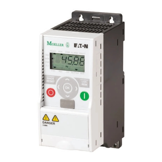
Component Identification
Identifies and labels the main components of the M-Max series inverter.
Checking the Delivery
Instructions for verifying the received product for completeness and damage.
Technical Data and Specifications
General Rated Operational Data
Provides general operational data including standards, certifications, and climatic proofing.
Power Connection Voltages
Lists part numbers and their corresponding power connection voltages, motor ratings, and frame sizes.
Description of the M-Max
Overview of M-Max Devices
Shows diagrams and lists components of M-Max devices in various frame sizes.
M-Max Features
Describes the basic functionality of the M-Max frequency inverter.
Block Diagram, Elements of M-Max Frequency Inverters
Presents a block diagram and explains the function of each element within the M-Max inverters.
Proper Use
Maintenance and Inspection
Recommends regular checks and maintenance measures for the frequency inverters.
Engineering
Introduction to Drive Systems
Introduces the chapter on energy circuits of drive systems for project planning.
Drive System (PDS) Components
Illustrates and lists components of a typical Power Drive System (PDS).
Electrical Power Network
Input Connection and Configuration
Details how M-Max inverters connect to AC power networks and configuration considerations.
Input Voltage and Frequency
Explains the standardized input voltages and frequency ranges supported by the inverters.
Safety and Switching
Fuses and Cable Cross-Sections
Guidelines for selecting appropriate fuses and cable cross-sections for power connections.
Residual-Current Device (RCD) Requirements
Explains the purpose and type of RCDs required for frequency inverters.
EMC Installation
EMC Measures in the Control Panel
Provides guidelines for EMC-compliant installation within control panels.
Electrical Installation
Connection to Power Section
Shows general connections for the frequency inverter in the power section.
Ground Connection
Details how to establish a proper protective ground connection for the device.
Connection on Control Section
Position of Control Signal Terminals
Shows the layout of control signal terminals under the front cover flap.
Control Signal Terminals Arrangement and Connections
Details the assignment and designation of all control signal terminals.
Error and Warning Messages
Error Messages Overview
Explains how fault messages are displayed and their impact.
Acknowledging Fault Messages (Reset)
Details the process for acknowledging and resetting fault messages.
Fault Log (FLT)
Explains how to access and view the log of the last nine detected faults.
Parameters
Control Unit Operation
Details the integrated control unit, including keypad and LCD display elements.
Display Unit and LCD Areas
Describes the LCD display unit, its areas, and operational data indication.
Setting Parameters
Parameter Menu Navigation
Explains the parameter menu structure and the Quick Configuration process.
Quickstart Wizard Guide
Guides the user through initial parameter configuration for application setup.
Digital Inputs (P3)
Digital Input Configuration Types
Describes Source and Sink types for digital inputs and their logic.
Control Logic Reaction to Signal Edges
Illustrates how digital inputs respond to rising or falling signal edges.
Start-Stop Command and Brief Instructions
Start-Stop Command Details
Describes start/stop commands with set acceleration ramps.
Motor Start Quick Instructions
A visual guide detailing the steps required to start the motor.
Error and Warning Messages
Error Message Identification
Explains how fault messages are displayed and their impact.
Fault Acknowledgment and Reset
Details the process for acknowledging and resetting fault messages.
Fault Log (FLT) Access
Explains how to access the fault log to review past errors.
Alarm Message Information
Explains warning messages indicating potential issues that can be prevented.
Parameters
Control Unit Overview
Details the components of the integrated control unit, including keypad and display.
Parameter Setting Guide
Provides a general guide to selecting and setting parameters.
Drives Control (P6)
Primary Remote Control Source
Sets the source for primary remote control (I/O, Keypad, Fieldbus).
Acceleration and Deceleration Time Settings
Explains how to set primary acceleration and deceleration times and their calculation.
Analog Input (P2)
Analog Input Connections AI1 and AI2
Illustrates analog input connections and configuration for AI1 and AI2.
Analog Input Signal Range and Scaling
Details analog input signal ranges, custom settings, and scaling examples.
Filter Time Constant for Analog Signals
Explains how to use filter time constants to reduce analog signal disturbance.
Digital Inputs (P3)
Digital Input Configuration Types
Describes Source and Sink types for digital inputs and their logic.
Control Logic Reaction to Signal Edges
Illustrates how digital inputs respond to signal edges.
Protective Functions (P8)
Protective Function Overview
Lists protective functions and their reactions to external influences.
Motor Heat Protection Configuration
Explains the motor temperature protection based on a calculated model.
Digital Outputs (P5)
Digital Output Types and Functions
Describes the three types of digital outputs: relays and transistor output.
Fixed Frequency Setpoint Value (P10)
Fixed Frequency Parameterization
Explains how fixed frequencies can be set and controlled.
Fixed Frequency Activation via Inputs
Details how FF1, FF2, and FF3 are activated via digital inputs.
V/Hz-Characteristic Curve (P11)
V/Hz Characteristic Control Options
Explains the V/f characteristic control and its selectable procedures.
Cut-off Frequency and Field Weakening
Defines the output voltage limit and field weakening range.
Braking (P12)
DC Braking Functionality
Explains the DC braking function, its effect, and limitations.
DC Braking Time Settings
Details parameters for setting DC braking time at start and stop.
Regenerative Braking
Explains regenerative braking and the role of the brake chopper and resistor.
Logic Function (P13)
Logic Linking of Inputs A and B
Explains how to logically link parameters P13.1 and P13.2 for digital outputs.
Second Parameter Set (P14)
Second Parameter Set Overview
Groups parameters for a second motor, allowing alternative operation.
Application Examples for Second Parameter Set
Shows practical application examples for the second parameter set.
System Parameter
Hard- and Software Information Parameters
Lists system parameters related to hardware and software versions.
Communication Parameters (RS485)
Details communication parameters, specifically for RS485 interface.
Operational Data Indicator (MON)
Display Navigation and Indicators
Explains how to use the MON menu to select and display operational data.
Status Displays Examples
Provides examples of how digital inputs/outputs status is displayed.
Setpoint Input (REF)
Setpoint Input via Operating Unit
Describes how to set the frequency setpoint value using the operating unit keypad.
Serial Interface (Modbus RTU)
Modbus Communication Overview
Provides an overview of the Modbus protocol and its application in industrial systems.
Modbus Network Configuration
Illustrates a typical Modbus network arrangement with M-Max inverters.
Modbus Parameters Setup
Lists essential Modbus parameters required for proper function.
Modbus Data Exchange
Illustrates the sequence of data exchange between a Modbus master and slave.
Appendix A
Special Technical Data
Presents technical data for M-Max inverters across different power classes and motor outputs.
Device Series Technical Data
Lists technical data specific to MMX11, MMX12, MMX32, MMX34, and MMX35 series.
Dimensions and Frame Sizes
Dimensions for FS1–FS3 Frame Sizes
Provides approximate dimensions for M-Max devices in frame sizes FS1, FS2, and FS3.
Dimensions for FS4 and FS5 Frame Sizes
Provides approximate dimensions for M-Max devices in frame sizes FS4 and FS5.
PC Interface Card
MMX-COM-PC Module Overview
Introduces the MMX-COM-PC module for PC connection and parameter management.
MMX-COM-PC Installation
Step-by-step guide for installing the MMX-COM-PC module.
Mounting Frame for Fieldbus Connection
MMX-NET-XA Mounting Frame Details
Illustrates the MMX-NET-XA mounting frame and its components.
Interface Cover Removal
Shows how to remove the interface cover from the MMX inverter.
MMX-NET-XB Interface Module
MMX-NET-XB Module Installation
Details the MMX-NET-XB module and its installation.
Cover Removal for FS4, FS5
Instructions for removing the cover of FS4 and FS5 inverter models.
Fieldbus Interface Card Options
PROFIBUS DP Fieldbus Interface Cards
Describes PROFIBUS DP interface cards and their connection.
DeviceNet Fieldbus Interface Card
Describes the DeviceNet interface card and its connection.
List of Parameters
Quick Configuration Guide
Provides a quick reference for essential parameters and their settings.
System Parameters in Quick Start
Lists system parameters relevant to quick start and default I/O assignments.
All Parameters
Parameter Selection Overview
Outlines how to select and access all available parameters.
Analog Input Parameter Configuration
Details the parameters for configuring analog inputs AI1 and AI2.
Drives Control Parameters
Primary Remote Control and Speed Reference
Sets primary control source and speed reference.
Appendix B
Door Panel Keypad Adapter System
Introduces the door keypad adapter system and its purpose.
Door Keypad Mounting Kit Components
Lists the components included in the door keypad mounting kit.
Door Keypad Mounting Procedure
Provides step-by-step instructions for mounting the door keypad.
Dimensions
Door Keypad Cut-out Dimensions
Specifies the dimensions required for the panel cut-out and screw holes.
Door Keypad Dimensions (Front and Side View)
Shows the front and side view dimensions of the door keypad.
Need help?
Do you have a question about the MMX32AA2D4N0-0 and is the answer not in the manual?
Questions and answers