Sign In
Upload
Download
Table of Contents
Contents
Add to my manuals
Delete from my manuals
Share
URL of this page:
HTML Link:
Bookmark this page
Add
Manual will be automatically added to "My Manuals"
Print this page
×
Bookmark added
×
Added to my manuals
Manuals
Brands
YOKOGAWA Manuals
Controller
YS1500
User manual
YOKOGAWA YS1500 User Manual
Programmable /indicating controller
Hide thumbs
1
2
3
Table Of Contents
4
5
6
7
8
9
10
11
12
13
14
15
16
17
18
19
20
21
22
23
24
25
26
27
28
29
30
31
32
33
34
35
36
37
38
39
40
41
42
43
44
45
46
47
48
49
50
51
52
53
54
55
56
57
58
59
60
61
62
63
64
65
66
67
68
69
70
71
72
73
74
75
76
77
78
79
80
81
82
83
84
85
86
87
88
89
90
91
92
93
94
95
96
page
of
96
Go
/
96
Contents
Table of Contents
Troubleshooting
Bookmarks
Table of Contents
Table of Contents
Foreword
Notice
Trademarks
Authorised Representative in the EEA
Revisions
Safety Precautions
Handling Precautions for the Main Unit
Checking the Contents of the Package
Symbols Used in this Manual
About an Electronic Manual
Introduction to Functions
Part Names
Front Panel Part Names
Swinging the Front Panel up and down
Part Names of the Internal Panel Seen with the Front Panel Swung up
YS1500/YS1700 Operating Procedure
Basic Operation
Overview of Display Switching and Operation Keys
Monitoring and Control of Regular Operations (Operation Display)
Monitoring and Operating the Operation Display
Monitoring and Operating the LOOP Display
Monitoring and Operating the METER Display
Monitoring and Operating the TREND Display
Monitoring and Operating the ALARM Display
Monitoring and Operating the DUAL Display
Switching of Operation Modes (Automatic Control (A), Manual Control (M), or Cascade Setting Automatic Control (C))
Switching by Keystroke
Switching in Response to Digital Input
Operating the Tuning Displays
Setting PID
Displaying the Operation Display While the Tuning Display Is Being Shown
Setting Alarms
Operating the Engineering Displays
Setting the Controller Mode
Setting the Control Type and Control Operation Formula
Setting the Scale and Decimal Point Position for Process Variables
Registering a Tag and Units
Tuning Guide
Starting Operations by Manual Operation
PID Parameter Tuning Guide and Automatic Adjustment
Installation and Wiring
Installation Location
Mounting Method
Mounting the Instrument Main Unit
Installing an Expandable I/O Terminal
External Dimensions/Panel Cutout Dimensions
YS1500/YS1700 Main Unit
Expandable I/O Terminal (YS010)
Expandable I/O Cable (YS011-03)
Wiring
Wiring Precautions
Terminal Diagrams of YS1500/YS1700 Single-Loop, Cascade, and Selector Modes
Terminal Diagrams of YS1700 Programmable Mode
Expandable I/O Terminal Diagram (YS1700 Basic Type (with Expandable I/O))
Transmitter Supply Power Wiring
Wiring for Digital Input/Output and FAIL Output
Direct Input Wiring (Optional Code /A0)
Wiring for the Serial Communication Interface (Optional Code /A31)
Wiring for Distributed Control System (DCS-LCS) Communication (Optional Code /A32)
Wiring for Peer-To-Peer Communication (YS1700, Optional Code /A31)
Wiring for the Ethernet Communication Interface (Optional Code /A34)
Wiring for Power Supply and Grounding
Installing the Terminal Cover
Troubleshooting
How to Take Actions if the ALM Lamp or FAIL Lamp Lights up
Backup Operation in the Event of Instrument Failure
Recovery Operations after Power Failures
List of Parameters
Tuning Parameters
Engineering Parameters
Advertisement
Quick Links
1
Table of Contents
2
Setting Pid
3
How to Take Actions if the Alm Lamp or Fail Lamp Lights up
Download this manual
User's
Manual
YS1500 Indicating Controller
YS1700 Programmable
Indicating Controller
Operation Guide
IM 01B08B02-01EN
IM 01B08B02-01EN
4th Edition
Table of
Contents
Previous
Page
Next
Page
1
2
3
4
5
Advertisement
Table of Contents
Need help?
Do you have a question about the YS1500 and is the answer not in the manual?
Ask a question
Questions and answers
Related Manuals for YOKOGAWA YS1500
Controller YOKOGAWA YS Series Technical Information
(2 pages)
Controller YOKOGAWA YS1000 Series User Manual
Programmable /indicating controller (96 pages)
Controller YOKOGAWA YS1000 Series User Manual
Standby manual station (26 pages)
Controller YOKOGAWA YS170 Tech Note
(12 pages)
Controller YOKOGAWA YS1700 Tech Note
Using 24v dc loop power supply (5 pages)
Controller YOKOGAWA YPP6200-6R0 Instruction Manual
Analog input flow rate/totalizer (47 pages)
Controller YOKOGAWA YPP6310 Instruction Manual
Pulse input batch controller (52 pages)
Controller YOKOGAWA PROPLUS YPP6210 Instruction Manual
Analog input batch controller (54 pages)
Controller YOKOGAWA FX103 User Manual
(263 pages)
Controller YOKOGAWA MC43 User Manual
Pneumatic indicating controller (44 pages)
Controller YOKOGAWA UP35A User Manual
Program (412 pages)
Controller YOKOGAWA UT520 User Manual
Digital indicating controllers (109 pages)
Controller YOKOGAWA TC 10-L Engineering Manual
Limit control type (20 pages)
Controller YOKOGAWA UT32A User Manual
Digital indicating controller (236 pages)
Controller Yokogawa FA-M3 System Upgrade Manual
(33 pages)
Controller YOKOGAWA UT320 User Manual
Digital indicating controllers (7 pages)
Summarization of Contents
Introduction and Overview
Foreword
Introductory remarks, notices, trademarks, and company representative information.
Package Contents and Functional Introduction
Details on product contents, manual features, and key operational terms.
Hardware Description
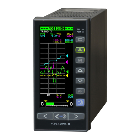
Part Names and Panel Description
Identification of front panel buttons, displays, and internal instrument components.
Operating Procedures
YS1500/YS1700 Initial Setup and Operation
Step-by-step guide for initial instrument setup, power-on, and basic configuration.
Basic Operation and Display Navigation
How to navigate between operation, tuning, and engineering displays using keys.
Monitoring and Control Operations
Regular Operations Monitoring Displays
Monitoring process variables (PV, SV, MV) and system status across LOOP, METER, ALARM, TREND, DUAL displays.
Operation Mode Switching Procedures
Procedures for changing between automatic, manual, and cascade control modes via keys or digital input.
Tuning and Configuration
Operating the Tuning Displays
Procedures for setting PID parameters and alarm limits through the tuning display.
Operating the Engineering Displays
Configuring controller mode, control types, scaling, tags, and other engineering settings.
Tuning Guide
Guidance on manual operation and automatic PID tuning methods for process control.
Installation and Wiring
Installation Guidelines
Recommended installation locations, mounting methods, and physical dimensions for the instrument.
Wiring Precautions
Essential safety precautions and guidelines before performing wiring.
Wiring Diagrams and Connections
Detailed diagrams for communication, input/output, and power wiring configurations.
Power Supply and Grounding Wiring
Procedures for connecting power supply and ensuring proper grounding.
Troubleshooting
Troubleshooting Guide
Steps for diagnosing and resolving instrument failures, alarms, and operational issues.
Handling Alarm and Fail Lamp Indications
Procedures for responding to ALM and FAIL lamp indications and diagnosing causes.
Instrument Failure and Recovery Operations
Procedures for backup operation during failure and recovery after power interruptions.
Parameter Reference
Parameter Overview and Tuning Parameters
Guide to understanding parameter structure and lists for tuning PID, STC, and control functions.
Configuration and Display Parameters
Parameters for system configuration, display settings, communication, I/O, and program settings.
Revision Information
Revision History
Details of manual updates, edition changes, and compliance information.
Table of Contents
Save PDF
Print
Rename the bookmark
Delete bookmark?
Delete from my manuals?
Login
Sign In
OR
Sign in with Facebook
Sign in with Google
Upload manual
Upload from disk
Upload from URL
Need help?
Do you have a question about the YS1500 and is the answer not in the manual?
Questions and answers