
Related Manuals for YOKOGAWA MC43


Summary of Contents for YOKOGAWA MC43
- Page 1 User’s Manual MC43 Pneumatic Indicating Controller IM 02M04B01-01EN IM 02M04B01-01EN 13th Edition...
-
Page 2: Table Of Contents
To Replace Screens ..................5-2 To Clean Nozzle ....................5-3 5.7 Controller Identification ................... 5-3 5.8 To Remove Measurement Pointer or Set Point Index ........5-3 To Remove Control Unit ................... 5-3 5.10 To Operate With Derivative Unit Removed ............. 5-4 13th Edition: Apr. 2017 (YK) IM 02M04B01-01EN All Rights Reserved, Copyright © 1983, Yokogawa Electric Corporation... - Page 3 General ......................A1-1 A1.2 Calibration and Replacement of Pressure Elements ......... A1-2 Appendix 2. Thermal Elements ..............A2-1 A2.1 General ......................A2-1 A2.2 Calibration and Replacement of Thermal Elements ........A2-2 Customer Maintenance Parts List MC43 Pneumatic Indicating Controller ......CMPL 02M04B01-01E Pressure Measuring Elements ...........CMPL 06P01B01-02E T1A Temperature Element ........... CMPL 06P01F01-02E Revision Information IM 02M04B01-01EN...
-
Page 4: Introduction
• The following safety symbols are used in this • Yokogawa makes no warranty of any kind with manual: regard to this material, including, but not limited to, implied warranty of merchantability and fitness for a particular purpose. -
Page 5: Safety Precautions
• Failure or damage due to modification or recommended. repair by the party except Yokogawa or who - Oil filter should be provided to remove oil is requested by Yokogawa. in the supply air. -
Page 6: Handling Cautions
(b) Ambient Atmosphere Also check that packings are included for T1A Do not install the MC43 controller in a corrosive temperature element. atmosphere. If this cannot be avoided, there must be adequate ventilation. -
Page 7: General
<2. General> General Outline Measurement Range: Standard Span Element The MC43 Controller continuously detects the Code SI Unit Metric Unit psi Unit difference between a process measurement and its 80 kPa 0.8 kgf/cm 12 psi set point, and produces an output air signal that is 0.1 to 1.37... -
Page 8: Principle Of Operation
<2. General> Principle of Operation (1) Proportional Control Feedback from Proportioning lever relay output Measurement Proportioning bellows Error Proportioning signal lever Proportioning Local or remote Flat spring bellows Flat spring Set point Striker bar Reset bellows Flapper nozzle Flapper Flapper Striker bar F0202.ai Reset restrictor For description, see Steps 1 through 4. - Page 9 <2. General> (3) Differential Gap Control See Figure 2.2. The batch attachment is installed in the feedback circuit (in front of the reset restrictor) of the MC43 controller (proportional plus integral operation). This batch attachment is normally set to Proportioning lever Flat spring operate when a pneumatic pressure of 1.0 kgf/cm...
-
Page 10: Model And Suffix Codes
Model Suffix Codes Description MC43 ......Pneumatic Indicating Controller Control Mode -A1 ...... -
Page 11: Installation
<3. Installation> Installation When installing the controller, refer to 1.3 “Selecting 2-inch Pipe Mounting Procedure the Installation Location” and 2.2 “Standard (1) Screw four bolts into the mounting hardware Specifications.” holes. (2) Using the bracket and nuts, put 2-inch pipe Mounting between the mounting hardware and the bracket. -
Page 12: Air Supply And Output Piping
<3. Installation> 3.2 Air Supply and Output Panel Mounting Procedure Piping (1) Loosen four screws and remove the mounting hardware. (2) Put the instrument in the panel and reassemble Regulator Shutoff valve the mounting hardware. 3/8-inch Tubing to control valve (3) Using two clamp screws, fix the instrument. For panel mounting, the bolts, bracket, etc. -
Page 13: Operation
<4. Operation> Operation Controller is available either with or without 1. To Transfer from Manual to Automatic Control Automatic-Manual Transfer System. The following Slowly turn set point knob (or adjust remote set covers the operation of controller having that point, if present) to move balance indicator ball system. -
Page 14: Controller Adjustments
Effect of Various Reset Times F0405.ai 6. If controller is not equipped with optional (1) Proportional Controller (Model MC43-A2) automatic-manual transfer, proceed to Step 7. 1. With PROPORTIONAL BAND at 400 or at safe If controller is equipped with transfer, start up in high value, make change in set point. - Page 15 Proportional Band, except doubling each setting instead of halving it. 3. Adjust RESET to final setting of Derivative in Lower control point Step 2. (5) On-Off Controller (Model MC43-A1) Time F0409.ai As the measurement crosses the control point 1. If “Increasing measurement, INCREASING (determined by the setting index), the control valve output”...
- Page 16 <4. Operation> 2. Rotate control dial so that arrow points to Pressure adjustment desired gap width with desired control action. Lock nut Manometer gauge 140 kPa (1.4 kgf/cm LOAD Regulator Screw F0412.ai Adjusting the Batch Attachment. 3. When measurement pointer (moving within gap) coincides with setting index, output (on output gauge) should change suddenly.
-
Page 17: Maintenance
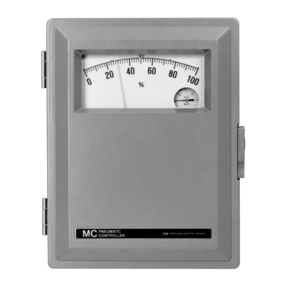
<5. Maintenance> Maintenance Basic Troubleshooting 5.2 Identification of Major Components in Controller DIFFICULTY: No reading (or very low reading) at output gauge. (1) Model MC43-N-N Set point and Measurement measurement dial Output gauge pointer Output gauge Set point index Measurement element (pressure type illustrated) F0501.ai 1. Check that 140 kPa (1.4 kgf/cm ) is supplied to controller. -
Page 18: To Clean Restrictor
NOTE Amplifier • Controller is equipped with either a locally- adjusted set point (set point knob, standard; MC43-N-N) or a remotely-adjusted set point (pneumatic set, optional; MC43- C-P). • If controller is equipped with optional automatic-manual transfer system (MC43- C-P). -
Page 19: To Clean Nozzle
Note hole that link is in. 2. Pass O.D 0.13 mm wire through opening into nozzle. 3. Replace parts tightening screw securely. 5.7 Controller Identification When consulting Yokogawa, always submit controller model and serial numbers found on data plate. Measurement Element Link inside control unit Range and Serial Number (see note below). -
Page 20: To Operate With Derivative Unit Removed
Remove derivative assembly from case. NOTE 5.11 Control Unit Alignment Alignment procedures for On-Off and Differential When using the control unit as Model MC43-A2, Gap, Controllers are on page 5-6. -A4 or -B4 after removal of the derivative assembly, replace the replay manifold with... -
Page 21: Alignment Procedure
<5. Maintenance> 5.12 Alignment Procedure Flapper Adjustment (If required in Step 2) (1) Controllers With Proportional, Reset, or Derivative Actions Set point index Output gauge Proportional band dial a. Make adjustment in black sector of dial at zero setting. Set point knob b. Support flapper assembly with finger during F0517.ai adjustment. - Page 22 <5. Maintenance> (2) Alignment Procedure On-Off Controller 4. Apply 140 kPa to controller. 5. Move measurement pointer slowly by hand from one end of scale to other end and then back again. Note scale readings at the two control points (where output changes abruptly; output is either 0 or 140 kPa).
-
Page 23: Internal Pneumatic Connection Identifications
<5. Maintenance> 5.13 Internal Pneumatic Connection Identifications Proportional Action Proportional + Integral Actions Key to Abbreviations Proportional + Derivative Actions P+I+D Proportional + Integral + Derivative Auto-man transfer system To nozzle in control unit Reset and Derivative Assemblies To Manifold To tee connecting Deriv. output and Reset restrictor P+I+D conns. -
Page 24: Appendix 1. Pressure Elements
A1-1 <Appendix 1. Pressure Elements> Appendix 1. Pressure Elements A1.1 General 3. With gas or steam applications, connections at the pipe or vessel are to be made on the top or Spiral Helical Bellows side. With liquid applications, connections are to be made on the side only. Pitch all horizontal lines for drainage or venting. - Page 25 A1-2 <Appendix 1. Pressure Elements> (4) Piping Arrangements To Zero (Gas application) Close valve A and open valve C. Use Zero Dry Gas Wet Gas adjustment to bring the pointer to zero. Close valve C and open valve A. Valve C can be used for initial drainage in wet gas applications with instrument below line.
- Page 26 A1-3 <Appendix 1. Pressure Elements> (2) Calibration Procedure (3) To Replace Measuring Element Element nameplate FA0106.ai FA0107.ai 1. Set pressure at minimum value (see range on 1. Disconnect link from pointer movement. Note element nameplate). which hole link is in. (A precalibrated link 2.
-
Page 27: Appendix 2. Thermal Elements
(Optional) twisted. If any part is damaged, the assembly (bulb, Affected by measuring span tubing, and helical element) must be returned to Yokogawa for repair. (4) Typical Temperature Installation Loosely coil excess tubing and secure in place. Avoid extremes of temperature in locating tubing. - Page 28 Fixed union element calibration. When ordering replacement (FB type) thermal element, specify the desired temperature range. Yokogawa will supply a precalibrated FA0206.ai element. If you wish to check or calibrate an In Lagged (Insulated) Pipe Line element yourself, use the following procedure.
- Page 29 A2-3 <Appendix 2. Thermal Elements> (2) Squaring Up of Linkage For Complete (3) Calibration Procedure Calibration If part have been replaced, or for some other reason a complete recalibration is necessary, square up the linkage before the actual calibration. 1. Check pointer reading at lower test temperature. If reading is not correct, use reference adjustment to reposition pointer.
- Page 30 A2-4 <Appendix 2. Thermal Elements> (4) Replacement of Thermal Elements 7. Remove three screws holding connector plate to case, and pull connector down with hand. 8. Remove seal plate from slit of case by pushing forward with finger. Zero adjustment screw FA0213.ai Sealplate 1.
- Page 31 A2-5 <Appendix 2. Thermal Elements> (5) Assembly/Disassembly of the Adjustable Union The adjustable union consists of a bushing, jam nut, spindle, gland nut, gland and packing. With air set, packing is attached to it. Without air set, packing is attached to bracket. • Assembling the Adjustable Union Follow the steps summarized in the table below to assemble the union. Step.
- Page 32 A2-6 <Appendix 2. Thermal Elements> • Installation of the Packing • Handling the Flattened Sides of the Spindle Thermo-sensitive bulb Bushing Jam nut CAUTION Gland nut Please employ packings without fail when mounting the temperature sensor. Open the slit on the packing and place 3 or 4 pieces(※) of the packing in position as illustrated below.
-
Page 33: Customer Maintenance Parts List
Y9422NP F9123EL Lock Assembly Y9412NP For Model MC43/SCT Hinge Screw F9123EA G9306WA F.H. Scew, M4 x 8 Label Y9408EU F9123PN CMPL 02M04B01-01E All Rights Reserved. Copyright © 1983, Yokogawa Electric Corporation 11th Edition: Nov. 2015 (YK) Y okogawa Electric Corporation... - Page 34 Feb. 2012 CMPL 02M04B01-01E Subject to change without notice.
- Page 35 Item Part No. Description Case – Button M0154RD Plate F9123HA Pan H. Screw, M5 x 10 Y9510JS Bracket E9123GE Pan H. Screw, M4 x 8 Y9408JS M0154NT Scale (specify model, range, unit and characteristic) Pan H. Screw, M3 x 4 Y9304JS Connection Assembly Below...
- Page 36 Jan. 2003 CMPL 02M04B01-01E Subject to change without notice.
- Page 37 Control Unit C0140ZS For Set Point Code "-P", contact Yokogawa Control Unit C0140ZT Restrictor Unit (Integral) Prior to Oct. 1, 1989: Contact Yokogawa F9138QS Restrictor Unit (Derivative) Prior to Oct. 1, 1989: Contact Yokogawa F9138RD Pan H. Screw, M4 x 8...
- Page 38 Jan. 2003 CMPL 02M04B01-01E Subject to change without notice.
- Page 39 Item Part No. Description Bracket F9123GE Column F9123JK Plate F9123QK F.H. Screw, M4 x 6 Y9406ES Transmitter Assembly F9120XP 10-32 x 3/8 Fil. H. Screw with Lockwasher 0006537 Output Gauge Below for Option Code/CAL-M F9123GJ for Option Code/CAL-E F9123GK for Standard and Option Code/CAL-Q, 0 to 200 kPa F9123GL for Option Code/CAL-B, 0 to 2 bar F9123GM...
- Page 40 Item Part No. Description F9123GA Bracket Y9814NU Hex. H. Bolt Y9800WU Washer F9123GC Bracket F9123GF Screw Assembly F9123GB Screw Y9601WU Washer Y9601BU F9123GG Screw Jan. 2003 CMPL 02M04B01-01E Subject to change without notice.
-
Page 41: Pressure Measuring Elements
Pan H. Screw, M4 x 8 F9123JJ Column F9147CW Screw F9123JP Tube B0102XK Compression Screw B0102XL Sleeve P0106KF X0101BE Link Assembly CMPL 06P01B01-02E All Rights Reserved. Copyright © 1983, Yokogawa Electric Corporation 8th Edition: Nov. 2015 (YK) Y okogawa Electric Corporation... - Page 42 Helical Element (P51 and P52) and Mounting Parts Item Part No. Description Below Helical Element Assembly P0106MA for ranges 1.37 to 1.51 MPa P0106MB for ranges 1.52 to 1.85 MPa P0106MC for ranges 1.86 to 2.28 MPa P0106ME for ranges 2.29 to 2.76 MPa P0106MF for ranges 2.77 to 3.44 MPa P0106MK...
-
Page 43: T1A Temperature Element
See GS 02D01J01 or 02M04B01) Link Assembly X0101BM Pan H. Screw, M4 x 6 Y9406JS Column F9123JK CMPL 06P01F01-02E All Rights Reserved. Copyright © 1983, Yokogawa Electric Corporation 4th Edition: Nov. 2015 (YK) Y okogawa Electric Corporation... -
Page 44: Revision Information
Revision Information Title : MC43 Pneumatic Indicating Controller Manual No. : IM 02M04B01-01EN Edition Date Page Revised Item 13th Apr. 2017 CONTENTS “1.1 Model and Specifications Check”→ “1.1 Model, Specifications, and Accessories check” Add “Revision Information” Add accessories check...
Need help?
Do you have a question about the MC43 and is the answer not in the manual?
Questions and answers