Table of Contents
Advertisement
Quick Links
TC 10 - L
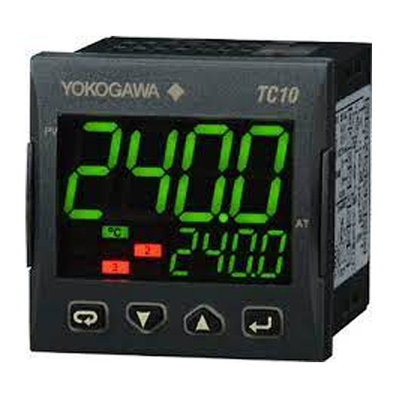
TC10
LIMIT CONTROL TYPE
Engineering Manual
Code: IM 05C01E81-12EN
First edition: Nov. 2019
Yokogawa Electric Corporation
2-9-32 Nakacho, Musashino-shi, Tokyo 180-8750 Japan
www.yokogawa.com/ns
1. OUTLINE DIMENSIONS (mm)
1.1 INSTRUMENT DIMENSIONS
48
PV
Optional
gasket
1.2 PANEL CUT-OUT
45
+0.6
mm
+0.023
1.78
Yokogawa Electric Corporation - TC10-L - ENGINEERING MANUAL - PAG. 1
48
11
AT
8 mm max.
65 mm min.
2.56 in min.
in
1.3 MOUNTING REQUIREMENTS
This instrument is intended for permanent installation, for
indoor use only, in an electrical panel which encloses the
rear housing, exposed terminals and wiring on the back.
Select a mounting location having the following characteristics:
1. It should be easily accessible;
2. There is minimum vibrations and no impact;
3. There are no corrosive gases;
4. There are no water or other fl uids (i.e. condensation);
5. The ambient temperature is in accordance with the
operative temperature (0 to 50°C);
6. The relative humidity is in accordance with the instrument
specifi cations (20 to 90%);
The instrument can be mounted on panel with a maximum
thickness of 8 mm.
When the maximum front protection (IP65) is
desired, the optional gasket must be mounted.
This is mandatory for FM approval.
2. CONNECTION DIAGRAM
ELECTRICAL CONNECTIONS
RS485
Analogue input
12VDC
(note)
PV
14
mV, V
4 to 20 mA
2 wire transmitter
12VDC
(note)
PV
4 to 20 mA
3 wire transmitter
2.1 GENERAL NOTES ABOUT WIRING
1. Do not run input wires together with power cables.
2. External components (like zener barriers, etc.) connected
between sensor and input terminals may cause errors in
measurement due to excessive and/or not balanced line
resistance or possible leakage currents.
3. When a shielded cable is used, it should be connected at
one point only.
4. Pay attention to the line resistance; a high line resistance
may cause measurement errors.
2.2 INPUTS
2.2.1 Termocouple Input
External resistance: 100W max., maximum error 25 µV.
Continuity detection current: 250 nA.
Cold junction: automatic compensation between 0 to 55°C.
Output 1: 4-20 mA
OP1
Limiter
Output
Output 4: 0-12V DO
OP3
OP4
(note)
Thermo-
mA
couple
Note: Terminal 4 can be programmed as:
- 0 to 12 V SSR Drive Output (OP4) connecting
Pt1000
Pt100
the load between terminals 4 and 16;
- 12 Vdc (20 mA) transmitter power supply
connecting the 2 wire transmitter between
terminals 4 and 1; for 3 wire transmitter connect
terminal 4 to transmitter power supply input and
terminal 1 and 2 to transmitter signal output.
TERMINALS
DI1
Pin connector
∅
1.4 mm max.
(0.055 in.)
L
Stripped wire
L:
5.5 mm
(0.21 in.)
Line
100 to 240 Vac
Neutral
2
+
1
Advertisement
Table of Contents

Related Manuals for YOKOGAWA TC 10-L


Summary of Contents for YOKOGAWA TC 10-L
- Page 1 2.2 INPUTS 2.2.1 Termocouple Input +0.6 +0.023 1.78 External resistance: 100W max., maximum error 25 µV. Continuity detection current: 250 nA. Cold junction: automatic compensation between 0 to 55°C. Yokogawa Electric Corporation - TC10-L - ENGINEERING MANUAL - PAG. 1...
- Page 2 30 m use a shielded wire. – Do not short-circuit the terminals of the SSR output. WARNING! Before connecting the output actuators, we recommend to confi gure the parameters to Yokogawa Electric Corporation - TC10-L - ENGINEERING MANUAL - PAG. 2...
-
Page 3: Serial Interface
1 x 10 2.3.4 Output 4 (OP4) SSR Output Out4 Logic level 0: Vout < 0.5 VDC; Logic level 1: 12 V ±20%, 20 mA max.. Note: Overload protected. Yokogawa Electric Corporation - TC10-L - ENGINEERING MANUAL - PAG. 3... -
Page 4: Technical Characteristics
Temperature drift: It is part of the global accuracy; Operating temperature: 0 to 50°C (32 to 122°F); Storage temperature: -20 to +70°C (-4 to +158°F); Humidity: 20 to 95% RH, not condensing. Yokogawa Electric Corporation - TC10-L - ENGINEERING MANUAL - PAG. 4... - Page 5 When the upper display is showing a group and the lower display is blank, this key allows to enter in the selected group. When the upper display is showing a parameter and Yokogawa Electric Corporation - TC10-L - ENGINEERING MANUAL - PAG. 5...
- Page 6 The instrument will show a measured value up to RTD Pt 100 (-200... 850°C/-328... 1562°F); 5% higher than [4] FSc value and then it will show Pt10 RTD Pt 1000 (-200... 850°C/-328... 1562°F); Yokogawa Electric Corporation - TC10-L - ENGINEERING MANUAL - PAG. 6...
- Page 7 +4 = Sensor break (burn out); [18] o4Ac - Out 4 action Available: When [16] o4F is different from “nonE”. Range: dir = Direct action; rEU = Reverse action;. Yokogawa Electric Corporation - TC10-L - ENGINEERING MANUAL - PAG. 7...
- Page 8 – High threshold equal to 10 (°C); an alarm that masks the alarm condition after a – Hysteresis equal to 25 (°C). set point change until process variable reaches the alarm threshold ±hysteresis. Yokogawa Electric Corporation - TC10-L - ENGINEERING MANUAL - PAG. 8...
- Page 9 Available: When [26] AL2t type is different form “nonE”. Range: From oFF (0) to 9999 seconds. Note: The alarm goes ON only when the alarm condition persist for a time longer than [32] AL2d time but the Yokogawa Electric Corporation - TC10-L - ENGINEERING MANUAL - PAG. 9...
- Page 10 Range: but = by keyboard [49] bAud - Baud rate di = by digital input Available: When [48] Add different from oFF. Range: 1200 = 1200 baud; 2400 = 2400 baud; Yokogawa Electric Corporation - TC10-L - ENGINEERING MANUAL - PAG. 10...
- Page 11 AH.P 10°C AH.P 100°C The most important step of the confi guration procedure is completed. In order to exit from confi guration parameter procedure, proceed as follows: • Push button. Yokogawa Electric Corporation - TC10-L - ENGINEERING MANUAL - PAG. 11...
-
Page 12: Operative Modes
(b), the upper display will be in green color and it shows that The way to confi rm are (according to the “diS” parameter): the PV is in the hysteresis area - pressing key for more than 3 seconds or Yokogawa Electric Corporation - TC10-L - ENGINEERING MANUAL - PAG. 12... - Page 13 7. It is possible to come back to the “standard display” by pushing the button for more than 3 seconds or by pushing no pushbutton for more than 30 seconds. Yokogawa Electric Corporation - TC10-L - ENGINEERING MANUAL - PAG. 13...
-
Page 14: Hardware Specifications
Out 1 Available: Optionally Output action: direct/reverse programmable Function: retransmission Output type: 0-20 mA, 4-20 mA, 0-10 V or 2-10V program- mable Isolation: isolated output Maximum load: 500 Ohm Yokogawa Electric Corporation - TC10-L - ENGINEERING MANUAL - PAG. 14... - Page 15 Baud rate: from 1200 to 38400 baud Multiple reading: max 16 word. Multiple writing: max 16 word. Parity: none Data format: 8 bit Start Bit : 1 Stop Bit: 1 Yokogawa Electric Corporation - TC10-L - ENGINEERING MANUAL - PAG. 15...
-
Page 16: General Notes
“Monitoring and control instruments”. Do not dispose of this product in domestic household waste. When disposing of product in the EU, contact your Yokogawa Europe B.V. offi ce. Yokogawa Electric Corporation - TC10-L - ENGINEERING MANUAL - PAG. 16... - Page 17 = Over-range and burn-out Out 4 function P.FAL = Power failure bo.PF = Over-range, Burn-out and power Fail On = Output ever ON (usable as auxiliary PWS for a transmitter). Yokogawa Electric Corporation - TC10 -L - ENGINEERING MANUAL - PAG. 17...
- Page 18 From 0.0 to 100% of the input span 0 = PU.SP > PV and SP / SP only (lower display) oP.SL Operative display selection 1 = SP > SP only (lower display) Yokogawa Electric Corporation - TC10 - L - ENGINEERING MANUAL - PAG. 18...
- Page 19 -1999 to A.H.P-10 (E.U.) A.L.o Adjust low Offset -300 to 300 (E.U.) A.H.P Adjust High Point A.L.P +10 to 9999 (E.U.) A.H.o Adjust High Offset -300 to 300 (E.U.) Yokogawa Electric Corporation - TC10 -L - ENGINEERING MANUAL - PAG. 19...
- Page 20 Yokogawa Electric Corporation - TC10 - L - ENGINEERING MANUAL - PAG. 20...
Need help?
Do you have a question about the TC 10-L and is the answer not in the manual?
Questions and answers