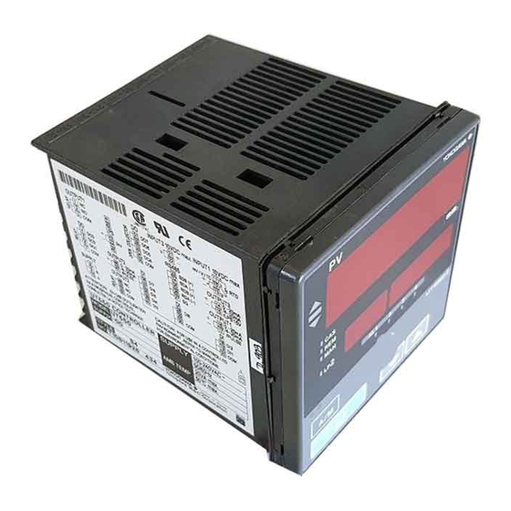
Summarization of Contents
Introduction to the User's Manual
How to Use the Manuals
Explains how to navigate and use the manual's sections effectively.
Manual Usage Guidelines
Provides important notes, guidelines, and applicable controller types for manual usage.
Safety Precautions
Safety Symbols and Warnings
Explains safety symbols (CAUTION, NOTE, IMPORTANT) and general safety precautions.
Force Majeure and Prohibitions
Outlines liability limitations, prohibitions on modification, and usage restrictions.
Installation Guide
Model and Suffix Codes
Details model numbers and their corresponding suffix codes for correct identification.
Installation Procedures
Provides instructions for physically installing the controller, including panel cutout dimensions.
Wiring and Hardware Specifications
Covers wire connection guidelines, cable specifications, and detailed hardware features.
Terminal Wiring Diagrams
Illustrates the electrical connections for various controller functions and models.
Initial Settings Configuration
Front Panel Overview
Identifies and describes the function of each part on the controller's front panel.
PV Input Configuration
Guides through setting the primary input signal type and its range.
Control Output Configuration
Explains how to define the type of control output signal for the controller.
Parameter Initialization and Alarms
Details parameter initialization and setting alarm types.
Controller Operations
Monitoring Operating Displays
Shows how to view operational status and key parameters on the controller.
Setpoint and Tuning Operations
Guides on setting target setpoints, PID parameters, and performing auto-tuning.
Operation Mode and Remote Control
Explains switching between AUTO/MAN, RUN/STOP, and Remote/Local modes.
Troubleshooting and Maintenance
Troubleshooting Guide
Provides a flow chart and steps for diagnosing and resolving operational issues.
Maintenance Procedures
Covers routine cleaning and procedures for replacing controller parts.
Parameters Reference
Parameter Maps and Lists
Visual guides and detailed descriptions of all controller parameters.
Parameter Categories
Details input, output, communication, and initialization parameter groups.
Function Block Diagrams
Single-loop Control Diagram
Visual representation of the functional logic for single-loop control.
Single-loop Heating/Cooling Control Diagram
Logic diagram illustrating heating/cooling control operations.
Single-loop Position-proportional Control Diagram
Logic diagram for position proportional control operations.


Need help?
Do you have a question about the UT550 and is the answer not in the manual?
Questions and answers