
Related Manuals for Aetechron 9205


Summary of Contents for Aetechron 9205
- Page 1 9205/9305 Operator’s Manual Wide-Bandwidth, High-Power, Multi-Channel Digital Amplifiers 574.295.9495 | www.aetechron.com 2507 Warren Street, Elkhart, IN 46516...
- Page 3 2507 Warren St. Elkhart, IN, 46516, U.S.A. receive an authorization to return the product for (574) 295-9495 service. All components must be shipped in a factory www.aetechron.com pack or equivalent which, if needed, may be obtained...
-
Page 4: Table Of Contents
Contents 1 Introduction ............................5 1.1 Features ..........................5 2 Amplifier Unpacking and Installation ....................6 2.1 Safety First ..........................6 2.2 Unpacking ..........................6 2.3 Installation ..........................6 3 Connections and Startup .......................7 3.1 Connecting the Load ......................7 3.2 Connecting the Input Signal ....................7 3.3 Optional Controls and Connectors ..................8 3.4 Connecting the AC Supply ....................8 4 ... -
Page 5: Introduction
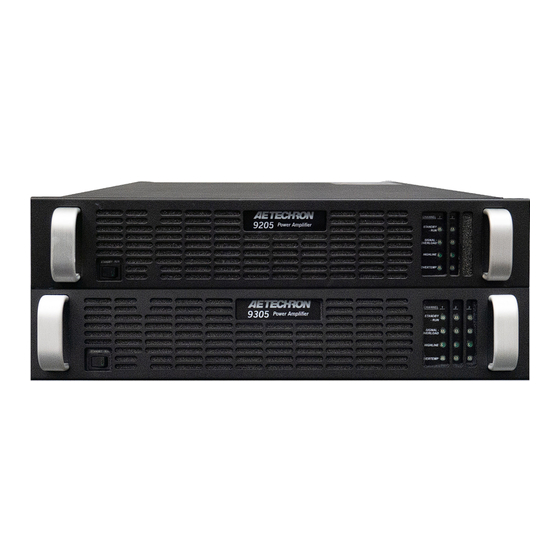
9205/9305 OPERATOR’S MANUAL – SECTION 1 Figure 1.1 – 9205 Front Panel 1 Introduction Performance Overview Congratulations on your purchase of a 9205 or Bandwidth DC - 250 kHz 9305 digital power amplifier. 9205/9305 amplifiers Minimum Drop/Rise Time 7 µs are 200Vp, DC-to-250 kHz capable amplifiers that offer a unique combination of switch-mode effi- Slew Rate Up to 150 V/µs ciency and linear-amplifier-like fidelity in a compact, Max Voltage 200 V portable package. They are able to drive virtually any type of load without a reduction in rated power, Max Current Up to 40 A... -
Page 6: Amplifier Unpacking And Installation
9205/9305 OPERATOR’S MANUAL – SECTION 2 Figure 2.1 – 9305 Back Panel 2 Amplifier Unpacking and Installation materials as evidence of damage and/or for return- 9205/9305 amplifiers are precision instruments that can be dangerous if not handled properly. ing the amplifier for repair. Lethal voltages are present in both the AC input 2.3 Installation supply and the output of the amplifiers. For this The 9205/9305 amplifier is packaged in a rugged reason, safety should be your primary concern powder-coated chassis. This chassis is 2U (rack when you setup and operate your amplifier. units) tall, and has rack “ears” on each side of the 2.1 Safety First front panel for mounting to a standard EIA (Elec- Throughout this manual special emphasis is tronic Industries Association) rack. Use standard placed on good safety practices. The following rack mounting hardware to mount the ampli- fier. Use nylon washers if you wish to protect the graphics are used to highlight certain topics that require extra precaution. powder-coat finish on the front of the amplifier. Optionally, the amplifier can be placed on a WARNING bench top; please keep in mind that the protective powder-coating can be scratched when placed WARNING alerts you to hazards that on other equipment or on a bench top, especially ... -
Page 7: Connections And Startup
9205/9305 OPERATOR’S MANUAL – SECTION 3 3 Connections and Startup tive terminals also can be connected to an external ground point such as the rack chassis, if desired. This section details the wiring and startup pro- See Figure 3.1. cedures for a 9205/9305 amplifier operating in Controlled-Voltage mode (factory default). Before connecting the amplifier inputs and outputs, make sure AC power is disconnected. Testing Before Controlled-Current Operation IMPORTANT: If your application requires Con- trolled Current operation, the 9205/9305 amplifier first should be wired and tested in Controlled- Voltage mode to verify that the amplifier and input Figure 3.1 – Connecting the Load signal are operating correctly. Once proper opera- tion is confirmed, refer to the Applications sec- Be sure to install the output safety covers after wir- tion of this manual for instructions on configuring ... -
Page 8: Optional Controls And Connectors
9205/9305 OPERATOR’S MANUAL – SECTION 3 that are high quality and shielded to minimize Inlet wiring must support the rated current. noise and to guard against possible feedback. The amplifier must be protected by fuses or circuit 3.3 Optional Controls and Connectors breakers that protect the power inlet wiring with a The following controls and connectors are pro- maximum rating of no more than 30A. vided on the amplifier back panel to allow for ad- 3.4.2 AC Inlet Connections ditional monitoring, configuration and control of the Always operate the amplifier from the proper AC amplifier output. mains. 9205/9305 amplifiers require single-phase, 3.3.1 Current Monitor Connectors 50-60 Hz, 100-250 VAC, at 30A with no more than Unbalanced BNC ports are provided on the ampli- ±10% variance above or below the line voltage. fier back panel, one for each channel, to allow for ... - Page 9 9205/9305 OPERATOR’S MANUAL – SECTION 3 Start-up Procedure 1. Turn down the level of your sig- nal source on each channel being utilized. 2. Press the front-panel Standby-Run switch to the Run position to ener- gize the amplifier. 3. Wait until the Run/Standby indicator turns solid green on each channel being operated. 4. For each channel being operated, adjust your input signal level to achieve the desired output level. Information subject to change 96-8007431_06-26-2024...
-
Page 10: Amplifier Operation
4 Amplifier Operation To release the amplifier from Standby mode: 1. Power Supply condition: If the amplifier’s 4.1 Front-Panel Controls and Indicators Power Supply indicator is lit, the amplifier is This section provides an overview of Front-Panel trying to absorb too much power. Turn the controls and indicators found on the 9205/9305 amplifier’s front Standby-Run switch to the amplifier. Refer fo Figure 4.1 for component loca- Standby position, and then either adjust the tions. input signal(s) or the load(s) to lower the power being returned to the amplifier. Turn the Stand- 4.1.1 Standby-Run Switch... - Page 11 9205/9305 OPERATOR’S MANUAL – SECTION 4 3. Over Current condition: This condition can • The amplifier is sinking too much power. Under occur when a very high current is being drawn these conditions, typically only the Power Sup- from the amplifier. Lower the operating level ply indicator will be lit. of the amplifier, then turn the amplifier’s front- • Too much power is being drawn from the power panel Standby-Run switch to Standby and then supply. This condition often occurs due to high- back to Run to reset the amplifier. If the fault current operation into a very small load. Under condition recurrs or does not clear, the ampli- these conditions, both the Power Supply and fier may require servicing. See the Trouble- the Overload indicators will typically be lit. shooting section for more information.
-
Page 12: Back-Panel Controls & Connectors
Back-Panel Controls & Connectors fier automatically returns to Run mode. See the This section provides an overview of Back-Panel Troubleshooting section for information on iden- controls and connectors found on the 9205/9305 tifying and correcting the cause of an Overtemp amplifier. Please refer to Figure 4.2 for component fault condition. locations. Over Current Condition: The amplifier monitors ... -
Page 13: Advanced Configuration
Select DC-coupled or AC-coupled operation. When this switch is in the LEFT position (default), • Adjust the amplifier gain from 2.5 to 20 in incre- the DC Servo function is disabled. ments of 2.5. • Limit current output from 15A to 60A in incre- ments of 15A. 9205/9305 Default DIP Switch Settings Red = Default DC SERVO OPERATION MODE COMPENSATION NETWORK 2 COMPENSATION NETWORK 1 CONTROL CONFIGURATION FOLLOWER MASTER COUPLING GAIN BIT 3 (MSB) ALL OFF = 2.5... - Page 14 9205/9305 OPERATOR’S MANUAL – SECTION 5 SW#2: Operation Mode CAUTION When the Operation Mode DIP switch is in the RIGHT position (default), the amplifier channel In Controlled-Current Mode, the load is part of the amplifier will operate in Controlled-Voltage mode, and the channel’s circuit, and the relationship of the load to the am- channel’s output voltage will be controlled by its plifier is critical. For proper and safe operation in Controlled- input voltage signal. When this switch is in the Current mode, you must obverve the following guidelines: 1. Properly attach a load before operating the amplifier LEFT position, the amplifier channel will operate in channel. Controlled-Current mode, and the channel’s output 2. DO NOT use a blocking capacitor. The load must have current will be controlled by its input voltage signal. a DC path.
-
Page 15: Custom Compensation
9205/9305 OPERATOR’S MANUAL – SECTION 5 is not adequate for your application and load, the ON = DIP Switch RIGHT OFF = DIP Switch LEFT Compensation Network 1 switch can be turned off SW#7 SW#8 SW#9 Gain and the Compensation Network 2 switch can be 20.0 used to enable a network that provides 80.6k ohm 17.5 resistance and 220 nF capacitance and should be 15.0 used with loads that are 500 μH to 2 mH. 12.5 10.0 NOTE: It is recommended to only use one of the compensation networks at a time. Having SW#3 ... -
Page 16: Applications
9205/9305 OPERATOR’S MANUAL – SECTION 6 6 Applications rent waveform to be like the input waveform (see Figure 6.2). 6.1 Controlled-Voltage vs. Controlled- Current Modes of Operation AE Techron 9205/9305 amplifiers can be field- configured to have one or more channels operate as a Voltage Amplifier (Voltage-Controlled Volt- age Source) or as a Transconductance Amplifier (Voltage-Controlled Current Source). The mode selection is made via the back-panel DIP switch #2. See the Advanced Configuration section for Figure 6.2 – Input to Output Comparison, more information. Controlled-Current Operation 6.1.1 Safety and Operation Consider- When configured as a Controlled-Voltage source ations for Controlled Current Operation (voltage amplifier), the channel will provide an ... - Page 17 9205/9305 OPERATOR’S MANUAL – SECTION 6 Compensation Network 1 or Compensation Net- (CV) or Controlled Current (CC) mode of opera- work 2 will be adequate for your application and tion. When operating the amplifier in Controlled load, please contact AE Techron Technical Sup- Voltage (CV) mode, compensation is not required. port for additional compensation options. However, when operating in Controlled Current (CC) mode, the channel’s load becomes an inte- The following section describes methods for gral part of the system. In order to ensure system determining proper compensation setting for your stability and to control available bandwidth, com- application when operating in Controlled-Current pensation via an RC network is required for CC mode. operation. The following steps will show you how 6.1.2 Selecting Compensation for to determine the proper compensation network for CC Operation your load to allow you to operate your amplifier ...
- Page 18 9205/9305 OPERATOR’S MANUAL – SECTION 6 STEP 3: Enable Compensation Network Compensation Network 1 DIP switch (SW#4) or If your load inductance is between 10 μH and 500 Compensatlon Network 2 DIP switch (SW#3) for μH, and your load resistance is less than 5 ohms, the amplifier channel is set to the ON (RIGHT) then you can likely use Compensation Network position. 1 for your application. If your load inductance is between 500 μH and 2 mH, and your load resis-...
-
Page 19: Driving Reactive Loads
9205/9305 OPERATOR’S MANUAL – SECTION 6 6.2 Driving Reactive Loads 1. Configuration: The default DIP switch settings Like all switching amplifiers, 9205/9305 ampli- can be used when configuring the amplifier as fiers are able to reuse the energy returned from a split-phase supply. See Figure 5.1 for the reactive loads. Unlike purely resistive loads, loads default DIP switch settings. Note that if your with some reactance (either capacitive or induc- application requires alternate DIP switch set- tive) will store energy during part of a cycle, and tings to enable one or more options, we recom- then release some of this energy back later. This mend that the same settings be used for both energy is transferred back to the load through the legs of the supply. amplifier’s power supply. This allow the amplifier to deliver continuous apparent power that is up to WARNING five times the rated power of the amplifier when ... - Page 20 9205/9305 OPERATOR’S MANUAL – SECTION 6 B. Output Connections: Using wires termi- 1. Configuration: The default DIP switch settings nated with #10 spade or ring terminals, can be used when configuring the amplifier as connect the load across the Channel 1 a 3-phase supply. See Figure 5.1 for the de- output terminal marked “+” (positive) and fault DIP switch settings. Note that if your ap- the Channel 2 output terminal marked “+” plication requires alternate DIP switch settings (positive). Connect together the outputs to enable one or more options, we recommend from each channel marked “–” (negative/ that the same settings be used for all legs of ground). the supply. 2. Wiring (refer to Figures 6.6) C.
-
Page 21: Maintenance
9205/9305 OPERATOR’S MANUAL – SECTION 7 7 Maintenance To ensure adequate cooling and maximum ef- ficiency of the internal cooling fans, the amplifier’s Simple maintenance can be performed by the user front and rear grills should be cleaned periodically. to help keep the equipment operational. The fol- To clean the amplifier grills and filter, complete the lowing routine maintenance is designed to prevent following steps: problems before they occur. See the Trouble- 1. Disconnect the amplifier from its power source shooting section, for recommendations for re- via external mechanical disconnect or breaker. storing the equipment to operation after an error 2. The front grill is secured to the amplifier front condition has occurred. panel by magnets. Pull out on the grill to re- Preventative maintenance is recommended after lease it from the front panel. -
Page 22: Troubleshooting
9205/9305 OPERATOR’S MANUAL – SECTION 8 8 Troubleshooting If the amplifier does not return to run mode, check to see if the High/Low Line, Overtemp, or Fault 8.1 Introduction & Precautions LEDs are lit, and then follow the instructions in this section for remedying the fault condition and This section provides a set of procedures for iden- returning the amplifier to Run mode. tifying and correcting problems with the 9205/9305 amplifier. Rather than providing an exhaustive and If the remedies given fail to restart the amplifier, detailed list of troubleshooting specifications, this the amplifier may require servicing. See the Fac- section aims to provide a set of shortcuts intended tory Service Information at the end of this section. -
Page 23: Amplifier Overheats (Over Temp Fault Condition)
9205/9305 OPERATOR’S MANUAL – SECTION 8 To clear the fault condition, first turn the amplifier’s 2. Visually inspect fans to assure correct opera- tion while amplifier is On (I). Any inoperative, front Standby-Run switch to the Standby posi- visibly slow, or reverse-spinning fan should tion, then reduce the input signal or increase the be replaced. Please see the Factory Service load impedance on one or more channels to lower information at the end of this section. the current requirements. Turn the Standby-Run switch to the Run position to resume amplifier An OverTemp condition places the amplifier in operation. Standby mode. If the OverTemp pulse is ex- tremely short, as in the case of defective wiring or Note that if more than one channel is being used, switches, the OverTemp pulse may be too brief to ... -
Page 24: Factory Service
9205/9305 OPERATOR’S MANUAL – SECTION 8 3. Turn off the AC mains. All service units must be given Return Authoriza- tion by AE Techron, Inc. before being returned. 4. Turn AC mains power back on. If the Fault LED Return Authorizations can be requested on our doesn’t illuminate again, press the Standby- website or by contacting our Customer Service Run switch to place the amplifier in Run mode Department. and turn the signal source on. 5. If the Fault LED is still illuminated and the Fault Please take extra care when packaging your am- condition doesn’t clear, return the amplifier for plifier for repair. It should be returned in its original Factory Service. See the Factory Service infor- packaging or a suitable alternative. Replacement mation at the end of this section. packaging materials can be purchased for a nomi- nal fee. 8.8 Factory Service If the troubleshooting procedures are unsuccess-...
Need help?
Do you have a question about the 9205 and is the answer not in the manual?
Questions and answers