Advertisement
- 1 WARNINGS & IMPORTANT SAFETY INSTRUCTIONS
- 2 FEATURES AND BENEFITS
- 3 INTRODUCTION
- 4 INSTALLATION GUIDE
- 5 USER GUIDE
- 6 DISPLAY DRILL / CUTOUT TEMPLATE
- 7 REDARC's contact details
- 8 Documents / Resources
WARNINGS & IMPORTANT SAFETY INSTRUCTIONS
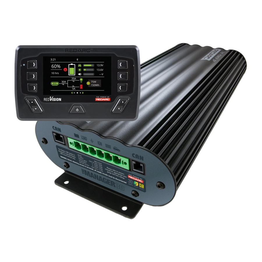
THE MANAGER30
The Manager30 Battery Management System is a complete charging solution for your Lead Acid or LiFePO4 Auxiliary or House battery. The system incorporates 12 V Solar, 110 V AC and 12/24 V DC inputs to provide a 12 V charging output at a maximum 30 A rating. The system also includes a Display which provides information such as current, voltage and temperature as well as a simplified battery percentage and charge rate. This information can also be displayed via the RedVision App on your Smartphone.
SAVE THESE INSTRUCTIONS — THIS MANUAL CONTAINS IMPORTANT SAFETY INSTRUCTIONS FOR THE MANAGER30 BATTERY MANAGEMENT SYSTEM THAT SHALL BE FOLLOWED DURING INSTALLATION, OPERATION AND MAINTENANCE OF THE UNIT.
DO NOT OPERATE THE BATTERY CHARGER UNLESS YOU HAVE READ AND UNDERSTOOD THIS MANUAL AND THE CHARGER IS INSTALLED AS PER THESE INSTALLATION INSTRUCTIONS. REDARC RECOMMENDS THAT THE CHARGER BE INSTALLED BY A SUITABLY QUALIFIED PERSON.

RISK OF EXPLOSIVE GASES:
WORKING IN THE VICINITY OF A LEAD-ACID BATTERY IS DANGEROUS. BATTERIES GENERATE EXPLOSIVE GASES DURING NORMAL OPERATION. FOR THIS REASON, IT IS OF UTMOST IMPORTANCE THAT YOU FOLLOW THE INSTRUCTIONS EACH TIME YOU USE THE CHARGER.

- The Battery Charger should not be used by persons (including children) with reduced physical, sensory or mental capabilities, or lack of experience and knowledge, unless they are supervised or have been instructed on how to use the appliance by a person responsible for their safety. Children should be supervised to ensure that they do not play with the Battery Charger.
- Do NOT alter or disassemble the Battery Charger under any circumstances. All services or repairs must be returned to REDARC for repair. Incorrect handling or reassembly may result in a risk of electric shock or fire and may void the unit warranty.
- Use of an attachment not recommended or sold by REDARC may result in a risk of fire, electric shock, or injury to persons.
- GROUNDING AND AC POWER CORD CONNECTION INSTRUCTIONS — Charger shall be grounded to reduce risk of electric shock. Charger is equipped with an electric cord having an equipment-grounding conductor and a grounding plug. The plug is to be plugged into an outlet that is properly installed and grounded in accordance with all local codes and ordinances.
![]()
Do not alter AC cord or plug provided — where it does not fit outlet, have proper outlet installed by a qualified electrician. Improper connection increases the risk of an electric shock. (If the supply cord is damaged, it must be replaced by the genuine REDARC part or assembly available from the manufacturer or service agent). - Cable and fuse sizes are specified by various codes and standards which depend on the type of vehicle the Battery Charger is installed into. Selecting the wrong cable or fuse size could result in harm to the installer or user and/or damage to the Battery Charger or other equipment installed in the system. The installer is responsible for ensuring that the correct cable and fuse sizes are used when installing this Battery Charger. The fuse must be UL Listed / UL Recognized.
- When charging a battery, make sure the settings at the Battery Setup menu on the Remote Monitor are correct for the type of battery under charge. Charging a battery with the wrong profile may cause the Battery Charger to indicate a fault or give misleading results and cause injury to persons, damage to the Battery Charger and/or property. Noticeable oscillations between Boost and Absorption stages indicate the wrong choice of battery type. Check and adjust battery type. If you are unsure of the battery type or settings to use, set to the Gel setting.
- Only use the Battery Charger for charging Standard Automotive Lead Acid, Lead Crystal, Calcium Content, Gel, AGM, SLI, Deep Cycle or Lithium Iron Phosphate type 12 V batteries.
- Do NOT try to charge non-rechargeable batteries.
- When using the Battery Charger to charge a Lithium Iron Phosphate battery, only batteries that feature an inbuilt battery management system featuring inbuilt under and over voltage protection and cell balancing are suitable.
- NEVER smoke or allow a spark or flame in vicinity of battery. This may cause the battery to explode.
- Be extra cautious so as to reduce the risk of dropping a metal tool onto a vehicle battery. Doing so might cause the battery to spark or might short-circuit the battery or other electrical parts that may cause an explosion.
- Remove personal metal items such as rings, bracelets, necklaces, and watches when working with a lead-acid battery. A lead-acid battery can produce a short-circuit current high enough to weld a ring or the like to metal, causing a severe burn.
- A SPARK NEAR A BATTERY MAY CAUSE THE BATTERY TO EXPLODE. TO REDUCE THE RISK OF A SPARK NEAR A BATTERY WHEN CONNECTING THE BATTERY INSTALLED IN A VEHICLE TO THE BATTERY CHARGER, ALWAYS DO THE FOLLOWING:
Always wire the Output Connector before connecting it to the Battery Charger. During connection of the unit, the Battery Output (positive) must be connected first, followed by the Ground (chassis) terminal. The chassis connection should be made away from the battery and fuel lines. DC Input (positive) should be connected last. Once all connections are wired to the Output Connector, plug the connector into the Main Unit.
When disconnecting the Battery Charger, remove the AC Connector first, followed by the CAN connection then the Output Connector from the Main Unit. The DC Input should be disconnected next, followed by the Ground (chassis) connection, then the Battery Output connection if complete removal is necessary.

- PERSONAL SAFETY PRECAUTIONS
To assist with the safe operation and use of the Battery Charger:- Consider having someone close by to come to your aid when you are using the Battery Charger.
- Have plenty of fresh water and soap nearby in case battery acid contacts skin, clothing, or eyes.
- Wear complete eye protection and clothing protection. Avoid touching eyes while working near a battery.
- If battery acid contacts your skin or clothing, remove the affected clothing and wash the affected area of your skin immediately with soap and water. If battery acid enters your eye, immediately flood the eye with running cold water for at least 10 minutes and seek medical assistance immediately.
- To improve user safety it is recommended to control the charger and monitor the charging process using the remote away from the vicinity of the battery being charged.
NOTICE
- Do NOT connect computers or IT equipment to the Charger front panel connector or remote. Damage may occur.
- It is recommended to leave the remote connected at all times to the base unit.
- The Main Unit must be fixed using suitable screw mounts. Failure to adequately mount the unit, such as using adhesives to mount the unit will result in unreliable operation of the charger.
- When using the charger in Storage mode, make sure that there is a valid charging source and that all loads are disconnected from the house battery. Failure to do so may cause the house battery to be under charged, give false readings on the State of Charge indicator and possibly cause damage to any loads connected.
- A partially shaded panel (or low-light conditions such as dawn or dusk) will increase the target solar panel voltage level to match the maximum power point. In this situation solar will be selected as a source however little or no current will be flowing into the battery.
- Modification of the 'Advanced Settings' menu items affect the way the Battery Charger responds to charging situations. Modification of these settings may result in the Battery Charger not functioning at 100% of its capacity. These settings should only be modified if absolutely necessary and when the effects of the changes are 100% understood.
- Touring mode will achieve it's best charge level if a Storage mode charge has been recently performed.
- It is the installers responsibility to ensure their installation complies with any applicable legal and regulatory requirements.
FEATURES AND BENEFITS
- The Manager30 incorporates six products in one, it's a DC–DC charger, a 110 VAC Mains/Shore Power charger, a solar charger, a dual battery isolator, a load disconnect controller and a remote battery monitor. The Manager30 will automatically select between charging sources, requiring no input from the operator during its operation.
- The Manager30 has no fan, which makes it super quiet and very reliable.
- The Manager30 is designed and manufactured in Australia, for Australian conditions, using the latest electronic and design technologies. It is manufactured with high-quality components to ISO9001 quality and ISO14001 environmental standards and backed with REDARC's quality service and two-year warranty.
- The Manager30 charging algorithm uses solar whenever possible making the unit more energy efficient and better for the environment.
- The Manager30's DC–DC charging enables optimal charging of house batteries, even if they have different chemical characteristics from the vehicle battery. The input voltage can be above, equal to or below the output voltage.
- State of Charge (SoC) indication means you will always know how fully charged the battery is and how much longer it will need to achieve full charge. An easy to operate, high-quality, user friendly graphical display module lets you know what's going on at all times.
- The Manager30 is very reliable and includes reverse polarity protection (without depending on fuses) and short circuit protection. The unit has undergone stringent safety and electrical compliance testing.
- The Manager30's easily selectable charging profiles make it suitable for charging all lead-acid battery types and suitably protected LiFePO4 battery types commonly used in modern travel trailers, motorhomes and Recreational Vehicles (RVs).
- The Manager30 disconnects automatically from the vehicle battery, so there is always power to start the car.
- Sophisticated fault detection monitors the house battery condition during all stages of charging, keeping you and your travel trailer/camper/RV safe.
- The Manager30 has a separate battery sensor to monitor battery conditions and state of charge even while The Manager30 is in standby mode. The battery sensor monitors current, voltage and temperature of the house batteries.
- Automatic temperature and voltage drop compensation.
INTRODUCTION
General Description
The Manager30 is designed to offer a complete solution to battery charging and maintenance needs for recreational automotive applications.
The Manager30 incorporates AC Mains/Shore Power, DC and Solar inputs to achieve the best charge to a house battery
The Display
The Manager30 comes with a Display designed to give you house battery information and charge status along with critical system information while charging is in progress.
With the Display, you can customize how your house battery is charged and monitor where the charge is coming from, keeping you in control at all times.
The Display can be surface mounted on a wall, or recessed (into the dashboard of an RV for example).
The Display also allows a Bluetooth connection to your Smartphone, via the RedVision App, which provides the same data and control available on the Display all in the palm of your hand.
The Kit Includes

Specifications


FIGURE 1.4.1: Main Unit Dimensions

FIGURE 1.4.2: Display Dimensions
Multi-stage Charging Process
The Manager30 incorporates two different multi-stage charging profiles – Touring (3-stage) and Storage (8-stage) – which can be selected in the System Mode menu (outlined in System Settings section of this manual) on the Display.
Touring Mode
Touring mode is designed for use when 'on the road'. Touring mode offers a 3-stage charging profile consisting of Boost, Absorption and Float stages (see Figure 1.5.1). In Touring mode, the house battery is monitored to detect only a limited number of faults such as short circuit, over current and over voltage. This allows The Manager30 to operate correctly even when loads are connected to the house battery. This mode will always produce an output (unless a fault condition is detected) and will cycle through the three stages as required to maintain the house battery as outlined in Figure 1.5.1.

FIGURE 1.5.1: Mode Charging Process
 NOTICE
Touring mode will achieve its best charge level if a Storage mode charge has been recently performed.
Storage Mode
Storage mode is designed to charge the house battery to its optimal level and maintain that level while your travel trailer or RV is in storage. This mode requires a valid charging source (110 V or solar and all loads to be switched off or disconnected from the house battery before charging. It uses a 8-stage* charging profile consisting of Desulphation*, Soft Start, Boost, Absorption, Battery Test, Equalize**, Float and Maintenance stages (see Figure 1.5.2).

FIGURE 1.5.2: Storage Mode Charging Process
*The Lithium profile does NOT incorporate a Desulphation stage.
**The Lithium, AGM and Gel profiles do NOT incorporate an Equalize stage
Storage mode is designed to detect a wide range of battery fault conditions, for more information on these fault conditions, please refer to section 'Fault Display'.
Unlike Touring mode, Storage mode does not cycle through the entire charge process. When the charging process is completed, The Manager30 will always remain in either Float or Maintenance stages. Float stage will provide the house battery with a 'trickle' charge whenever the house battery voltage drops below a predetermined threshold to ensure the battery stays charged. Maintenance stage turns The Manager30 output off, but continues to monitor the House Battery and will revert to Float stage when the House Battery drops below 12.7 V (12.8 V for Lithium) for 5 seconds or below 90% SoC for 1 hour.
NOTE: If The Manager30 is set to Storage mode and the vehicle is started The Manager30 will automatically switch to Touring mode once it senses an increase in input voltage from the alternator.
NOTICE
When using the charger in Storage mode, make sure that there is a valid charging source and that all loads are disconnected from the house battery. Failure to do so may cause the house battery to be under charged, give false readings on the State of Charge indicator and possibly cause damage to any loads connected.

When The Manager30 is set to 'Storage' mode and no valid charging sources are connected, it will enter a 'Sleep' mode 30 seconds after the last user interaction. The sleep mode is designed to limit the amount of current drawn from the output battery by the system whilst in Storage mode and does this by switching the screen and all non-essential functions off. The Manager30 will 'wake-up' from its Sleep mode if the power button is pushed or if any valid input source is sensed, though this may take 30-60 seconds to occur after the source is connected.
Maximum Charge Current Setting
The Manager30 allows the user to set the maximum charge current for their battery, making it suitable for charging batteries as small as 40 Ah in capacity. When the charge current is set below the maximum 30 Amps, the current supplied to charge the battery is restricted to the user setting. Any excess BMS1230S3 capacity is available to power loads running from the battery under charge.
If no loads are running from the battery, total current from The Manager30 will be restricted to the level set by the user.
Recommended batteries
Because of the rapidly changing nature of batteries and battery technology, REDARC avoid recommending specific battery makes or models. Instead, we recommend consultation with a battery specialist, and that the batteries used be ![]() UL approved where possible.
UL approved where possible.
Regardless of the battery(s) chosen, check the manufacturer's datasheet to ensure maximum charge current and maximum charge voltage does not exceed the battery's ratings.
Green Power Priority
The Manager30 is designed to charge from multiple sources simultaneously to charge the auxiliary/ house battery. If the Solar power input is available the maximum available solar power will be used before topping up the output charging current from another source if available (e.g. AC Mains/Shore Power).
Priority is given to Solar then to AC Mains power, then to DC Vehicle power.
INSTALLATION GUIDE
System Layout

FIGURE 2.1.1: System Layout
Mounting Instructions
This section describes how to mount the three major components of The Manager30: the Main Unit, the Display and the Battery Sensor.

FIGURE 2.2.1: The Manager30 System
Mounting the Main Unit
Do NOT expose the Main Unit to rain, snow, spray or bilge water. For optimum operation, The Manager30 should be mounted where the temperature is nominally below 95°F (35°C) and does not exceed a maximum of 140°F (60°C). The Main Unit must not be mounted in the engine bay and it is not suitable for charging any battery at engine bay temperatures.
The Main Unit must not be installed in a location with any less than 4" (100 mm) clearance at the top of the Main Unit, to allow for airflow across the heatsink fins.
The Main Unit and Battery Sensor should be installed as close as practicable to the house battery. The cable length should be less than 6 1/2 feet (2 m).
The Main Unit must be mounted to a flat, solid support using 1/4" (M6) sized screws or bolts, using all four mounting holes.
NOTICE
The Main Unit must be fixed using suitable screw mounts. Failure to adequately mount the unit, such as using adhesives to mount the unit will result in unreliable operation of the charger.
REDARC recommends that the Main Unit be mounted to optimize airflow past the heatsink. Mounting the unit horizontally (see Figure 2.2.1.1)

FIGURE 2.2.1.1: Horizontal mounting is recommended
is recommended and mounting vertically (see Figure 2.2.1.2)

FIGURE 2.2.1.2: Vertical mounting is acceptable
is still acceptable. Do NOT mount the unit as shown in Figure 2.2.1.3.

FIGURE 2.2.1.3: Do NOT mount the unit upside down
Mounting the Display
The Display should be mounted inside the vehicle (Refer for a 1:1 cutout template). It is however acceptable to mount the Display in any convenient location, as long as it is protected from harsh environments such as being exposed to rain or severe amounts of dust or full-time direct sunlight.

Ensure that the Display is not mounted in vehicle head-impact zones. Doing so may result in injury to the driver and/or passenger in the event of an accident.
Ensure the Display is not mounted where it may distract the driver of the vehicle. Distracting the driver may result in an accident.
Removing the Display Fascia

NOTICE
Refer to 1:1 cutout template
Flush Mount Drill/Cut Dimensions

Surface Mount Drill/Cut Dimensions

Mounting the Battery Sensor
The length of cables on the Battery Sensor to connect to the Main Unit and the House Battery will dictate the allowable mounting distance from the battery however REDARC recommend mounting the Battery Sensor as close to the House Battery as possible.
The sensor must be mounted where the red temperature/voltage sensor module can be bolted to the battery positive terminal of the House Battery.
The Battery Sensor should be mounted to a solid surface using two suitably sized screws for attachment. Figure 2.2.3.1 illustrates how to mount the Battery Sensor.

FIGURE 2.2.3.1: Mounting the Battery Sensor
DC Cable Size Requirements
Cable and fuse sizes are specified by various codes and standards which depend on the type of vehicle the Battery Charger is installed into. Selecting the wrong cable or fuse size could result in harm to the installer or user and/or damage to The Manager30 or other equipment installed in the system. The installer is responsible for ensuring that the correct cable and fuse sizes are used when installing the Battery Charger.
The Manager30 is capable of drawing up to 50 A from the Vehicle Battery (which may be several feet/ meters from its installation location) and is limited to 30 A output to the House Battery. The installer needs to ensure the appropriate cable is used to connect the positive and negative connections of The Manager30 to both the Vehicle Battery and the House Battery. The Manager30 will operate with less efficient cabling however for best performance, high-quality cable connections should be used to minimize voltage drop and efficiency losses.
Input Wire Diameter Selection
REDARC recommends the installer use cabling and connections between 8B&S and 6B&S automotive.
REDARC recommends that the input wire be of the size outlined in Figure 2.3.1.1.
| Distance from input vehicle battery to The Manager30 | Recommended Cross Sectional Area (mm²) | Recommended Diameter Equivalent |
| ≤ 10' (3 m) | 8 | 8AWG / 8B&S |
| > 10' (3 m) | 13 | 6AWG / 6B&S |
FIGURE 2.3.1.1: Recommended input cable size
Output Wire Diameter Selection
REDARC recommends the installer use cabling and connections between 8B&S and 6B&S automotive.
REDARC recommends that the output wire be of the size outlined in Figure 2.3.2.1. For longer runs, using 10 mm² is recommended, however this will lower efficiency by up to 3% (the recommended maximum length is 16'5" (5 m).
| Distance from The Manager30 to House battery | Recommended Cross Sectional Area (mm²) | Recommended Diameter Equivalent |
| ≤ 5' (1.5 m) | 8 | 8AWG / 8B&S |
| > 5' (1.5 m) | 13 | 6AWG / 6B&S |
FIGURE 2.3.2.1: Recommended output cable size
REDARC recommend using the SBI12-BLD as the 12 V relay for setting up the Load Disconnect
Feature for nonessential Loads.

Similarly, the SBI12-LLD is recommended for use between the Auxiliary/House battery and the Essential Loads in a Lithium Battery setup, to protect the Lithium battery from excessive discharge.
The Manager30 Wiring Connections
REDARC recommends that this unit be installed by a suitably qualified person.
The AC/Shore Power connection must be connected to an earthed socket outlet. Do not use The Manager30 AC input if the cord is damaged. Use of a non-genuine or damaged AC input cord may result in a risk of fire, electric shock, or injury to persons. (If the supply cord is damaged, it must be replaced by a special cord or assembly available from the manufacturer or service agent).
Always wire the Output Connector before connecting it to the Main Unit. During connection of the unit, the Battery Output (positive) must be connected first, followed by the Ground (chassis) terminal. The chassis connection should be made away from the battery and fuel lines. DC Input (positive) should be connected last. Once all connections are wired to the Output Connector, plug the connector into the Main Unit.
When disconnecting remove the Output Connector from the Main Unit first. The DC Input should be disconnected next, followed by the Ground (chassis) connection, then the Battery Output connection.
Load Disconnect Feature
The Load Disconnect wire is a ground switch to activate a relay for disconnection of any loads running from the house battery. The relay must be 12 V with a maximum coil current of 1 A and resistor or diode suppression is recommended. The Load Disconnect feature must be activated in the User Menu as explained in BMS Settings Section of this manual.
Ignition Trigger Feature
The Ignition Trigger wire is used to turn the DC charging source on with ignition. In most circumstances this wire does not need to be connected. This feature is designed to allow vehicle with Variable Voltage alternators to trigger the DC Input. Figure 2.4.4.2 shows how to wire the Ignition Trigger wire.
The Ignition Trigger feature must be activated in the User Menu as explained in BMS Settings Section of this manual.
Connecting the Battery Sensor
Wire the Battery Sensor as shown in Figure 2.4.3.1 ensuring that the "BNEG" stud connects to the
House Battery negative terminal and the "GND" stud connects to the vehicle common ground point. The Battery Positive Lead connects to the house battery positive terminal, this lead measures voltage and temperature at the battery. Connect the CANBus Connection cable to either of the main unit CANBus interfaces.
NOTE: When securing the cables to either side of the shunt using the provided nut, ensure the head of the bolt is also held by a spanner, to prevent twisting and damage to the shunt. Do not over tighten.

FIGURE 2.4.3.1: Battery Sensor connections
Wiring the Main Unit
Refer to Figure 2.4.4.1 for required connections and to Figure 2.4.4.2 typical setup.

FIGURE 2.4.4.1: Required connections
NOTE: If a longer Display cable is required, a replacement CAT5 patch cable may be used, up to a length of 32' (10 m).
Typical Setup
*1 The size of this fuse relates to the total current draw of all the loads connected to the House Battery, and should be rated slightly higher than this. REDARC recommend the use of MIDI Style Fuses.
*2 Essential loads are loads which must be left on at all times, until the battery is flat. Non-essential loads are those switched off when the battery reaches a particular low-charge level, which can be set in the 'Advanced Settings' menu.
*3 Both CANBus connections can be used for either the Display or Battery Sensor
*4 Ensure the RED terminal on the Battery Sensor is connected to the Battery Positive Terminal.
A single fuse and holder setup from the Fuse Kits available from REDARC.
Part number FK40 (40 A) or FK60 (60 A)


Batteries
Working in the vicinity of a Lead-Acid battery is dangerous. Batteries generate explosive gases during normal operation. For this reason, it is of utmost importance that you follow the instructions each time you use the charger.
When charging a battery, make sure the settings at the Battery Setup menu on the Display are correct for the type of battery under charge. Charging a battery with the wrong profile may cause The Manager30 to indicate a fault or give misleading results and could result in damage to the battery. Noticeable oscillations between Boost and Absorption stages indicate the wrong choice of battery type. Check and adjust battery type. If you are unsure of the battery type or settings to use, set The Manager30 to the Gel setting.
Figure 2.5.1 and 2.5.2 show standard wiring for batteries in series and in parallel.

To ensure that all batteries are equally charged, loads and The Manager30 should be connected with ground and 12 V power connected diagonally opposite across all batteries as shown in Figure 2.5.2.
The Ah rating needs to be setup when prompted on first start up, these settings can also be modified in the "BMS Settings" menu (Refer BMS Settings Section).
To identify the Ah rating of batteries in parallel, add the rating of each battery in the bank together. For example, 3 batteries with an Ah rating of 100 Ah each will yield a total rating of 3 × 100 Ah or 300 Ah.
Batteries connected in series will assume the Ah rating of the battery with the lowest Ah rating. For example, if one battery is 50 Ah and the other is 100 Ah, the Ah rating for the series is 50 Ah.
Note: It is strongly recommended that house batteries connected in series be the same type and capacity.
MPPT Solar Regulator
The Manager30 is designed for use with 12 V solar panels. A minimum input voltage of 9.5 V is required to start charging from a solar source. Once charging has started, the operating voltage range of the solar input can go as low as 9 V and as high as 32 V; outside of this range, charging will stop.
The power output from solar panels varies depending on the amount of sunlight and the electrical load on the solar panel output. The Manager30 utilizes a Maximum Power Point Tracking (MPPT) algorithm on the solar input, to ensure that the greatest charge possible is transferred from the solar panels to the battery under charge. As conditions change, the MPPT algorithm adjusts its parameters accordingly, in order to maintain the optimum point at which the solar panels can deliver the most power.
An array of solar panels can be connected to The Manager30 solar input, on the condition that the open circuit output voltage of the array is at least 9.5 V and does not exceed 32 V*. For this reason, 12 V panels must be connected in parallel (Refer to Figure 2.6.1). So long as the voltage requirements are met, there is no limit to the number of panels that can be connected in a solar array; however The Manager30 will not draw more than 520 W from the solar input.
For installations with a single 12 V solar panel, a blocking diode is not necessary. For installations with an array of solar panels, please refer to the panel manufacturer's instructions for requirement and/or fitment of diodes.

FIGURE 2.6.1: Array of 12 V Solar Panels
USER GUIDE
The Display

The Display is the main user interface for the Manager30 System. The Display is designed to give you control of how the battery is being charged, as well as up-to-date house battery and charge information at any time during the charging process. You can check battery charge status, estimated charge time and State of Charge (SoC) per hour over a day and per day over a month. It also allows you to select charging profiles specific to the battery type and size. It also provides the Bluetooth® interface for the RedVision App.
With a RedVision Distribution Box connected, the Display allows control of an Inverter and up to 10 outputs along with information from 2x temperature and 6x water level sensors, bringing information and control to one place without the need for multiple displays and control panels.
NOTICE
Do not use chemicals or cleaning products as damage to the unit may occur.
Clean using a slightly damp cloth only.
Navigation
The Left/Right buttons are used to navigate the pages on the center of the screen.
The Up/Down buttons are used to navigate through options found on other pages or to cycle through devices on the Home Page when a Distribution Box is connected. The Left/Right and Up/Down functions are indicated on the screen.
Soft Keys
The Soft Keys functions will be indicated by and icon and these functions will change depending on the screen.
Power Button Function

Pushing the Power Button ONCE will open a Power Button instruction dialogue and allow switching between Storage and Touring modes.

Pushing the Power Button TWICE will invoke the 'Master Switch' function, when a Distribution Box is installed. This function switches a defined set of devices and can be customized, by the installer, to user specifications.

HOLDING the Power Button will put the screen into Standby mode. Pushing any button will wake the screen up again. When the system is set to 'Storage Mode' only the Power Button will wake the display up.
Notification Bar
 Bluetooth® Connected
 Master Switch Invoked
 Fault Indication
 Load Disconnect Invoked
 Storage Mode Selected
 Alarm Notification
Basic Screens
Home Screen

When connected to a Manager only, the RedVision display will provide real time information on the battery State of Charge, Sources, Current Flow and Solar Input *1 .
--
*1 The information provided on the home screen may vary depending on the system
Pushing Left reveals the Settings menu and Right reveals the information menu.
System Settings

This menu allows the user to change Display, System, BMS and Distribution Box settings (if fitted), selected by Soft Key.
Pushing the Up/Down arrows cycle through the available settings menus. Pushing the top left 'Back' Soft Key will return the user back to the Home Screen.
Changing Settings

Once the desired Settings Screen is selected using the Soft Keys, the available settings can be modified. Pushing the Up/Down arrows will cycle through the settings. Pushing the Left/Right arrows will modify the setting.
The 'Green Tick' Soft Key will save the adjustment, the 'Red Cross' Soft Key will cancel the changes.
BMS Information

The BMS information screen provides information on charge stage, current flow, State of Charge (SoC), solar input and battery status *2 .
The Soft Keys on the right link to performance logs for SoC/Day, SoC/ Hour and Solar Power input. The Soft Key on the left links to the Charging Source information page. Pushing the down arrow displays the Distribution Box Info. screen *3 .
--
*2 When used with a REDARC MANAGER system.
*3 When used with a REDARC RedVision Distribution Box.
State of Charge logs

The State of Charge log screens detail either the SoC on the hour for the previous 24 hours (State of Charge per Hour) or the maximum and minimum SoC each day for the previous 30 days. Pushing the Left and Right buttons at this screen will cycle through the logs, displaying the information at the top of the graph.
Solar Power input log

The Solar Power input log keeps track of the Solar Power generated per day for the previous 7 days.
Pushing the Left and Right buttons at this screen will cycle through the logs, displaying the information at the top of the graph.
Display Settings

Factory Settings
Key Sound: ON
Key Backlight: ON
Home Timeout: 1 min
Standby Timeout 1 min Brightness Minimum: 20%
Brightness Maximum: 100%
Clock Format: 12 Hour
The Display Settings screen allows setup and modification of Display specific settings as outlined below.

This icon will return to the Home Screen.

This icon links to the Screen Settings menu. This menu allows switching of Key Sounds and Backlight and modification of Screen Timeouts and Minimum and Maximum Screen Brightness levels.

This icon links to the Bluetooth® pairing screen. This screen allows connection of the Display to a standalone device via Bluetooth®. This process is explained further in The RedVision App Section.

This icon links to the Date and Time settings screen. The user is prompted to enter date and time upon first startup however should this need to be changed, it can be done in this menu.

This icon links to the Regional Settings menu. This menu allows toggle of the Clock format between 12 and 24 hour formats and the Temperature units between Celsius and Fahrenheit.
System Settings

The System Settings screen allows modification of the current operating mode as well as providing information on the system and previous fault history. Each icon is described below.

This icon will return to the Home Screen.

This icon links to the System Mode menu. This menu allows switching of the System Mode between Storage and Touring. Storage Mode will switch off all loads and set the Manager into Storage Mode should one be connected.

This icon links to the About Us screen. This screen provides contact information for REDARC.

This icon links to the RBus Diagnostics screen. This screen provides a serial number for each REDARC device connected to the system. More information on the selected device can be found by clicking the top right Soft Key.

This icon links to the Fault History screen. This screen provides a list of the 10 most recent faults. Clicking the top right Soft Key will provide more information on the selected fault.
BMS Settings

When a Battery Management System is connected, the system will allow setup and modification of a number of BMS settings as outlined below.

This icon will return to the Home Screen

This icon links to the Battery Information screen. This screen allows the user to set their battery type and size. This information is critical for the operation of the Manager product so it is important to ensure this is correct

This icon links to the Charger Settings screen. This screen allows setting of the DC input trigger on the Manager and allows modification of the Low Voltage and SoC alarm levels.

This icon links to the BMS Load Disconnect screen. This allows for setting of the Load Disconnect feature on the Manager.
NOTE: This feature operates similarly but independently to the Distribution Box Load Disconnect feature.
Fault Display

If The Manager30 detects a problem with the charging system that prevents it from continuing to charge the battery, it will alert you via a 'Fault' screen and an alarm buzzer, and will instantly terminate the charging cycle until the fault condition is cleared. The screen will give a brief description of the problem and will allow you to select either 'Clear' or 'Ignore'. Both options will clear the screen. After selecting 'Clear', however, The Manager30 will immediately check to see if the condition still exists. If it doesn't, the unit will restart charging. Selecting 'Ignore' will simply hide the fault screen for up to one minute. It will NOT allow The Manager30 to recommence charging unless The Manager30 itself detects the removal of the fault condition.
If The Manager30 detects a problem with the charging system that does not prevent it from charging the battery, it will alert you via a Warning screen and an alarm buzzer, and continue charging. The screen will give a brief description of the problem and allow you to select either 'Clear' or 'Ignore'. Both options will clear the warning screen. After selecting 'Clear', however, The Manager30 will immediately check to see if the fault condition still exists. If it does, it will display the warning screen again. Selecting 'Ignore' will prevent The Manager30 from detecting the same fault for up to one minute.
NOTE: If "Ignore" is selected but the fault is not removed, when the warning re-appears after one minute, it will not be accompanied by the alarm buzzer.
See a description of faults and warnings that can be detected by the Manager30.
If a Distribution Box is connected the system can also detect faults with fusing, switching and various connected devices.
Faults
| CHARGER FAULT MESSAGE | CAUSE | ACTION |
| Charger over current fault | An internal error has caused excessive current draw | Return to supplier |
| Charger over voltage fault | The output voltage is too high (above 18 V) | Check battery is correct type (12 V, 6 cell) |
| Charger over temperature. Allow to cool | The unit has over heated | Allow to cool, charging will recommence automatically |
| Output battery under temperature fault | Output battery is below the minimum charging temperature | Charger will halt charging until battery temperature has increased above the minimum charging temperature |
| Output battery over temperature fault | Output battery is above 140°F (60°C) | Charger will halt charging until battery is below 131°F (55°C) |
| Dry cell detected in output battery | Charger has detected a dry cell in output battery | Replace battery |
| Shorted cell detected in output battery | Charger has detected a shorted cell in output battery | Replace battery |
Warnings
| CHARGER WARNING MESSAGE | CAUSE | ACTION |
| AC supply over voltage | The internal AC converter output voltage is too high | Contact supplier |
| AC supply over temperature. | The internal AC converter temperature is too high | Allow to cool If problem persists, contact supplier |
| DC supply over voltage | The DC input voltage is too high (over 32 V) | Check DC input, refer to specified input range |
| Solar supply over voltage | The solar input voltage is too high (above 32 V) | Check solar input, refer to specified input range |
| No battery sensor connected | The supplied battery sensor is not connected or is faulty | Connect battery sensor, if faulty return to supplier |
| Battery SoC low! Disconnect all loads | House battery is almost flat | Reduce/remove loads on house battery |
| Battery voltage low! Disconnect all loads | Loads exceeding charge available from input sources | Connect additional input source or disconnect loads |
| Bad cable detected | Too much voltage drop between charger and battery sensor | Check cable for correct sizing requirements |
| Load Disconnect output shorted | Load disconnect is connected directly to battery supply or is overloaded | Check wiring and ratings If problem persists, contact supplier |
Other issues
| FAULT | ACTION |
| Low output current can occur when the unit is hot and temperature derating is implemented to protect the Charger | Check that the unit is in a well ventilated space |
| The current display shows a negative current when there are no loads on the house battery and the house battery is charging | The current shunt connection is reversed |
| Noticeable oscillations between Boost and Absorption stages | Check and select the correct battery type |
The RedVision App
The RedVision App allows users to monitor up-to-date house battery and charge information at any time during the charging process. Users can check battery charge status, estimated charge time and State of Charge (SoC) per hour over a day and per day over a month. It also allows users to select charging profiles specific to the battery type and size. When connected to a RedVision Distribution Box, the app allows users to control multiple on-board devices from their smartphone; for example turning lights, inverter, water pumps and other loads such as televisions, electric steps and fridges on or off. It also provides the user with the ability to monitor water levels and temperature. The RedVision App replicates MOST of the display and switching features of the Display.

NOTICE
The RedVision App and its interactions with the Manager30 System have not been tested on all smartphones available on the market so is not guaranteed to work on all devices. However, the app has been designed to work with:
- IOS 11. 1 (or later)
- Android 7.0 (or later)
- Bluetooth® 4.0 (or later).
For a full list of compatible devices as they become validated, please visit: www.redarc.com.au/redvision
Bluetooth® Pairing Instructions
- Install the RedVision
![]()
![]()
or Configurator App
![]()
(scan the corresponding QR code![]()
![]()
or search for "REDARC" on your device's app store)
![www.apple.com]()
![play.google.com]()
- On the Display, press Left, navigate to display settings and press the Bluetooth® Soft Key – this should say "Your display is ready for pairing"
![]()

- Open the RedVision or Configurator App
- On the RedVision App, if you get a "No device selected" pop-up, click "Configure"
![]() . If using the Configurator App, move to step 5.
. If using the Configurator App, move to step 5.

- Choose your Display from the list (this should match the serial number on your Display, which can be found in R-Bus Diagnostics on the display
![]() )
) - Read and agree to any disclaimers displayed.
- Wait for passcode prompt (this may pop up or show up as a notification depending on your phone)
- Enter the 6-digit code shown on the Display
![]()

- "Your device is paired."
![]()


 . If using the Configurator App, move to step 5.


Subsequent Connections
Once a smartphone has been paired with a RedVision Display, it will automatically reconnect with that Display when the app is opened.
If you have multiple Redvision Displays paired and you want to switch between which is connected to your smart phone, tap on the 3 gear symbol on the top left of the app.
The available paired Displays will be shown. Select the one you want to connect to.

Connecting Multiple Devices
The RedVision Display can manage multiple paired devices although only one can be connected at a time. Closing the app will disconnect the device from RedVision.
Pairing a second device is the same as above.
When the RedVision App is closed on one device, the RedVision App can be opened on another device and will connect automatically if it has previously been paired.
Frequently Asked Questions
Q I have damaged my Power Cable and need to replace it, do I have to buy a special kind of cable.
A To ensure the correct operation of The Manager30, REDARC advise that if the supply cord is damaged it must be replaced by a special cord available from the manufacturer.
Q I am running a load from my house battery, but it does not seem to register on The Manager30 Display, why can I not see this current draw?
A This is generally caused by incorrect wiring of the Battery Sensor. Ensure no equipment earths go direct to the house battery negative or to the house battery end of the shunt. They must all go to common or chassis ground or to the ground end of the shunt.
Q My Input Status screen shows a voltage on the Solar input but the bar graph shows that no charge is coming from the Solar input, what does this mean?
A A partially shaded panel (or low-light conditions such as dawn or dusk) will increase the target solar panel voltage level to match the maximum power point. In this situation solar will be selected as a source however little or no current will be flowing into the battery.

Q I have just finished wiring The Manager30 and when I turn the unit on the Display says 'No Battery Sensor Detected', is my unit faulty?
A The Battery Sensor has a time-out function in-built into the unit. If the Battery Sensor is wired to Power and Ground for a considerable amount of time before the Main Unit is connected this message may appear. Try disconnecting the unit completely in the following order. Ensure all charging sources are disconnected. Unplug the Green connector on the charger. Disconnect the Battery Sensor red connection on the auxiliary battery. Leave all disconnected for 60 seconds. Reconnect in reverse order and retry. If the fault still occurs, there may be an issue with your Manager, please contact REDARC Electronics for support.
DISPLAY DRILL / CUTOUT TEMPLATE

REDARC's contact details
North America
power@redarcelectronics.com
www.redarcelectronics.com
Telephone:
+1 (704) 247-5150 if you are calling from the USA
+1 (604) 260-5512 if you are calling from Canada
(calls are answered between 8am and 5.30pm Australian Central Standard Time (ACST)
Documents / Resources
References
![www.redarc.com.au]() RedVision
RedVision![www.apple.com]() App Store - Apple
App Store - Apple![play.google.com]() Google Play
Google Play![redarcelectronics.com]() REDARC : Automotive Electronics, DC Charging & Brake Control
REDARC : Automotive Electronics, DC Charging & Brake Control

Download manual
Here you can download full pdf version of manual, it may contain additional safety instructions, warranty information, FCC rules, etc.
Advertisement


Need help?
Do you have a question about the Manager30 and is the answer not in the manual?
Questions and answers