Advertisement
Table of Contents
Advertisement
Table of Contents

Summary of Contents for Redarc BCDC1220
- Page 1 In-vehicle 3-Stage 12V Battery Charger BCDC1220 & BCDC1220-IGN...
- Page 2 Do NOT alter or disassemble the Battery Charger under any circumstances. All faulty units must be returned to REDARC for repair. Incorrect handling or reassembly may result in a risk of electric shock or fire and may void the unit warranty.
-
Page 3: Table Of Contents
5 Two Year Warranty Specifications Part Number BCDC1220 BCDC1220-IGN Continuous Current Rating Input Fuse Rating 40A (Not Supplied) REDARC FK40 recommended Output Fuse Rating Output Power 300W DC Input Voltage Range 9-32V 9-32V Output Battery Type Standard Lead Acid, Calcium content, Gel & AGM type only Charging Profile 14.6... -
Page 4: Product Function
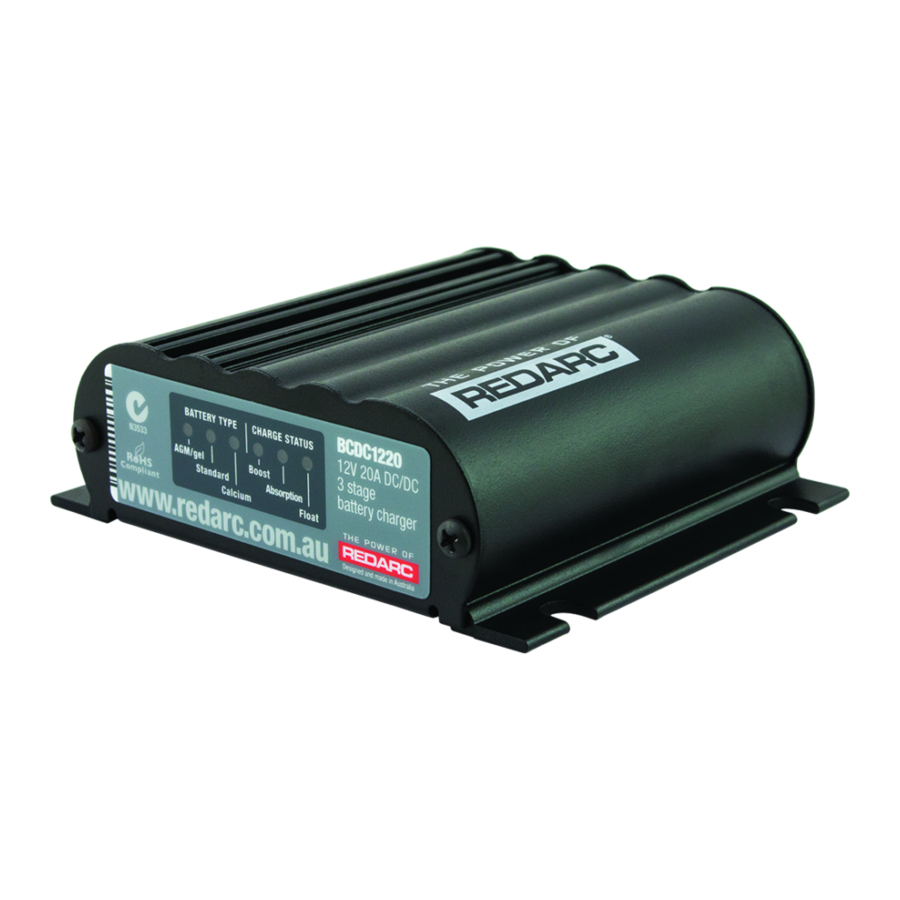
The BCDC1220(-IGN) is a multi stage, 12V, 20A, DC-DC battery charger that operates from an input of either 12V or 24V nominal. The input voltage of the BCDC1220 can be above, below or equal to the output voltage making it ideal for charging from a 24V vehicle or charging an auxiliary 12V battery where the distance from the main battery may cause a significant voltage drop. -
Page 5: Charging Algorithm
PRODUCT FUNCTION Charging Algorithm When the BCDC1220(-IGN) is turned on, it will move into the Boost stage. The Boost stage maintains a constant current until the battery voltage reaches the Absorption Voltage. The current during Boost stage may vary throughout operation in order to maintain a safe operating temperature, or to limit the difference between input and output voltages. -
Page 6: Installation
NOTE: Appropriate connections must be made to the wires with a continuous current rating of at least 20A for the BCDC1220(-IGN). Failure to do so may cause damage to the unit and vehicle. -
Page 7: Blue Wire - Input Trigger
12V Starter battery only Red Wire Input Source Positive 2.1.2 BCDC1220-IGN Vehicle To charge from either a 12V or 24V Variable Voltage or Ignition Smart Alternator system the BLUE ‘Input Trigger’ wire must always be connected to the vehicle ignition. -
Page 8: Bcdc1220
INSTALLATION ORANGE wire - Battery Type Select The ORANGE wire is used to select the Maximum output voltage. This is achieved by connecting in the following way: Connected To select Profile A leave the ORANGE wire Orange Wire disconnected. This will set the Maximum voltage to 14.6V To select Profile B connect the ORANGE wire to Orange Wire... -
Page 9: Brown Wire - Auxiliary Battery Positive
INSTALLATION BROWN wire - Auxiliary Battery Positive Brown Wire The BROWN wire should be connected to the auxiliary battery’s positive terminal. The unit should be a maximum of 1 metre in cable length from the battery. Auxiliary Appropriate size fuses should be used as per the Battery specifications table on page 2. -
Page 10: Wiring
8 B&S Wiring The wires on the BCDC1220(-IGN) unit carry peak currents of up to 30 Amps and it is important to make a good, low resistance, electrical connection that will not degrade over time. Failure to make a good, reliable contact may result in breakdown of the wire insulation and cause a short circuit, or worst case a fire. - Page 11 Fuse Fuse Battery config wire All ground points must Start Auxiliary be connected to chassis Battery Battery earth. Figure 2.7a - BCDC1220 12V Starter battery installation BCDC1220-IGN INPUT Load Loads Fuse Fuse Fuse Battery config wire To vehicle ignition All ground points must...
- Page 12 To vehicle ignition All ground points must Auxiliary Start be connected to chassis Battery Battery earth. Figure 2.7c - BCDC1220 & BCDC1220-IGN 24V installation BCDC1220 & BCDC1220-IGN INPUT INPUT INPUT 30A N/O Relay To vehicle ignition Load Loads Fuse...
-
Page 13: Fusing
INSTALLATION Fusing A single fuse and holder REDARC recommend using MIDI style bolt down fuses as setup from the Fuse Kits they ensure a low resistance connection. The REDARC available from REDARC. Part number FK40 (40A). FK40 fuse kit is recommended. -
Page 14: Frequently Asked Questions
The BCDC1220(-IGN) will turn OFF for a split second every 100 seconds to measure the unloaded voltage at the battery. When the BCDC1220(-IGN) turns off it is not drawing any load from the start battery, no load means that there is no voltage drop over the cable run. This allows the BCDC1220(-IGN) to measure the actual battery voltage, or the voltage at the battery. - Page 15 • Friendly, personalised, professional service and product support In the unlikely event that a technical issue arises with a Redarc product, customers are encouraged to initially contact the Redarc Technical Support Team on (08) 8322 4848 power@redarc.com.au for prompt and efficient diagnosis and product support.
- Page 16 Free technical assistance! please contact REDARC Electronics 23 Brodie Road North, Lonsdale SA (08) 8322 4848 power@redarc.com.au www.redarc.com.au Copyright © 2016 REDARC Electronics Pty Ltd. All rights reserved. www.redarc.com.au WARBCDC1220 - REV6...


Need help?
Do you have a question about the BCDC1220 and is the answer not in the manual?
Questions and answers