Table of Contents
Advertisement
Quick Links
Advertisement
Table of Contents

Related Manuals for Redarc Manager15


Summary of Contents for Redarc Manager15
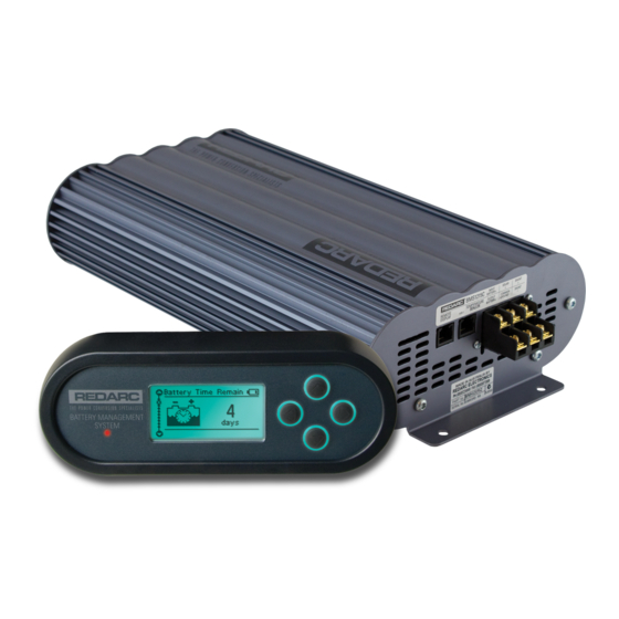
- Page 1 MANAGER Battery Management System BMS1215S3...
-
Page 2: Warnings And Safety Instructions
REDARC for repair. Incorrect handling or reassembly may result in a risk of electric shock or fire and may void the unit warranty. Use of an attachment not recommended or sold by REDARC may result in a risk of fire, electric shock, or injury to persons. - Page 3 WARNINGS & SAFETY INSTRUCTIONS Only use the Battery Charger for charging Standard Automotive Lead Acid, Calcium Content, Gel, AGM, SLI, or Deep Cycle type 12V batteries. NEVER smoke or allow a spark or flame in vicinity of battery. This may cause the battery to explode. Be extra cautious so as to reduce the risk of dropping a metal tool onto a vehicle battery.
-
Page 4: Table Of Contents
1. Mounting the Main Unit 2. Mounting the Remote Monitor 3. Mounting the Battery Sensor 3. DC Cable Size Requirements 4. The Manager15 Wiring Connections 1. Load Disconnect Feature 2. Ignition Trigger Feature 3. Connecting the Battery Sensor 4. Wiring the Main Unit 5. -
Page 5: Features And Benefits
The Manager15 will automatically select between charging sources, requiring no input from the operator during its operation. 2. The Manager15 has no fan or mechanical relays, which makes it SUPER quiet and very reliable. 3. The Manager15 is designed and manufactured in Australia, for Australian conditions, using the latest electronic and design technologies. -
Page 6: Introduction
INTRODUCTION General Description The Manager15 is designed to offer a complete solution to battery charging and maintenance needs for recreational automotive applications. The Manager15 incorporates AC, DC and Solar inputs to achieve the best charge to a house battery. The Remote Monitor... -
Page 7: Specifications
General Specifications Main Unit Dimensions 445x185x79mm Remote Dimensions 186x74x29mm Kit Weight 5.5kg Warranty 2 years * The Manager15 will only charge the battery when the battery temperature is between 0°C and 60°C in order to protect the battery from damage. - Page 8 INTRODUCTION Figure 1.4.1 - Main Unit Dimensions Figure 1.4.2 - Remote Monitor Dimensions...
-
Page 9: Multi-Stage Charging Process
This allows The Manager15 to operate correctly even when loads are connected to the house battery. This mode will always produce an output (unless a fault condition is detected) and will cycle through the three stages as required to maintain the house battery as outlined in Figure 1.4.1. - Page 10 The Manager15 output off, but continues to monitor the house battery and will revert to Float stage when necessary. NOTE: If The Manager15 is set to Storage mode and the vehicle is started The Manager15 will automatically switch to Touring mode once it senses an increase in input voltage from the alternator.
-
Page 11: Maximum Charging Current Setting
Any excess current is used to power loads running from the battery under charge. If no loads are running from the battery, total current from The Manager15 will be restricted to the level set by the user. -
Page 12: Installation Guide
The Manager15 240VAC Mains Power Figure 2.1.1 - System Layout Mounting Instructions This section describes how to mount the three major components of The Manager15: the Main Unit, the Remote Monitor and the Battery Sensor. Figure 2.2.1 - The Manager15 System... -
Page 13: Mounting The Main Unit
REDARC recommends that the Main Unit be mounted to optimise airflow past the heatsink. Mounting the unit horizontally (see Figure 2.2.1.1) is recommended and mounting vertically (see Figure 2.2.1.2) is still acceptable. -
Page 14: Mounting The Remote Monitor
INSTALLATION GUIDE 2.2.2 Mounting the Remote Monitor The Remote Monitor should be mounted inside the caravan or RV using the template provided inside the box. It is acceptable however to mount the Remote Monitor in any convenient location, as long as it is protected from harsh environments. - Page 15 INSTALLATION GUIDE Wall Mount Use the template provided (Page 36) Attach the Back Plate to the wall to mark the position and drill and cut using 4 suitably sized countersunk the mounting holes into the wall. screws. Feed the Remote Monitor cable Clip the Inner Assembly into the through the hole and connect it to Back Plate.
- Page 16 INSTALLATION GUIDE Removing the Remote Monitor The locking tabs on the back of the The locking tabs can be accessed Inner Assembly need to be unclipped through holes on the top of the from the Back Plate. backing plate when installed. Insert a flat-head screwdriver at a When the screwdriver is in a vertical slight angle towards the front of the...
-
Page 17: Mounting The Battery Sensor
Battery Charger. The Manager15 is capable of drawing up to 30A from the Vehicle Battery (which may be several metres from its installation location) and is limited to 15A output to the House Battery. - Page 18 INSTALLATION GUIDE 2.3.1 Input Wire Diameter Selection REDARC recommends the installer use cabling and connections between 8B&S and 6B&S automotive. REDARC recommends that the input wire be of the size outlined in Table 2.3.1. Distance from input to Recommended Cross...
-
Page 19: The Manager15 Wiring Connections
The AC power connection must be connected to an earthed socket outlet. Do not use The Manager15 AC input if the cord is damaged. Use of a non-genuine or damaged AC input cord may result in a risk of fire, electric shock, or injury to persons. (If the supply cord is damaged, it must be replaced by a special cord or assembly available from the manufacturer or service agent). -
Page 20: Connecting The Battery Sensor
INSTALLATION GUIDE 2.4.3 Connecting the Battery Sensor Wire the Battery Sensor as shown in figure 2.4.1.1 ensuring that the “BNEG” stud connects to the House Battery negative terminal and the “GND” stud connects to the vehicle common ground point. Connect the CANBus Connection cable, the cable with the RJ12 connector, to the CANBus network via the T-Piece supplied (see figure 2.4.2). - Page 21 INSTALLATION GUIDE...
-
Page 22: Batteries
Monitor are correct for the type of battery under charge. Charging a battery with the wrong profile may cause The Manager15 to indicate a fault or give misleading results and could result in damage to the battery. Noticeable oscillations between Boost and Absorption stages indicate the wrong choice of battery type. -
Page 23: Mppt Solar Regulator
An array of solar panels can be connected to The Manager15 solar input, on the condition that the open circuit output voltage of the array is at least 17.5V and does not exceed 32V. -
Page 24: User Guide
USER GUIDE Remote Monitor The Remote Monitor is designed to give you control of how the battery is being charged, as well as up-to-date house battery and charge information at any time during the charging process. You can check battery charge status, estimated charge time and State of Charge (SOC) per hour over a day and per day over a month. -
Page 25: Initial Setup
When charging a battery, make sure the settings at the Battery Setup menu on the Remote Monitor are correct for the type of battery under charge. Charging a battery with the wrong profile may cause The Manager15 to indicate a fault or give misleading results and could result in damage to the battery. -
Page 26: User Menu
first charge cycle (Calculating) and the battery size input by the user at setup to determine what the full State of Charge should be. Once The Manager15 has calculated the full state of charge for the system this screen will display either the Time to Full Charge or the Battery Time Remaining, depending on whether the house battery is currently being charged or discharged. - Page 27 The Output Status screen displays a summary of the current flow of the system. The screen will display current from The Manager15 unit, current in to or out of the battery and current provided to the loads. The direction of the current flow is indicated by the arrows, and a moving white dot.
-
Page 28: Settings Menu
When charging a battery, make sure the settings at the Battery Setup menu on the Remote Monitor are correct for the type of battery under charge. Charging a battery with the wrong profile may cause The Manager15 to indicate a fault or give misleading results and could result in damage to the battery. - Page 29 Restore Factory Settings Screen Modification of the ‘Advanced Settings’ menu items affect the way The Manager15 unit responds to charging situations. Modification of these settings may result in the unit not functioning at 100% of its capacity. These settings should only...
- Page 30 USER GUIDE The MaxCharge Current setting refers to the amount of current permitted by The Manager15 to charge the battery, up to a maximum of 15 Amps. Set Charging Current Screen R-Bus Diagnostics Screen Advanced Settings Screen Low SOC Alarm Screen If the Charging Current setting is set lower than 15 Amps the excess current will be used to supply the loads running from the battery under charge.
- Page 31 Load Temporarily Connected The DC Input Trigger allows you to select whether you would like your DC input to be triggered via Ignition, automatically via The Manager15, or at a specific voltage. Set DC Input Trigger Screen Load Disconnect Screen...
-
Page 32: Fault Screens
Change Setting Cancel Setting Change Setting This screen is used by REDARC to identify problems with a The Manager15 setup and does not need to be accessed unless requested by REDARC Technicians. Start Process/ More Info Set DC Input Trigger Screen... -
Page 33: Troubleshooting
Ignore Fault Troubleshooting The Manager15 is designed to detect and advise the operator of a variety of fault conditions and will terminate the charging cycle immediately should a critical fault be detected. This ensures that it will not attempt to charge a faulty battery, which protects The Manager15, house battery and most importantly the user. - Page 34 USER GUIDE Faults CHARGER FAULT MESSAGE CAUSE ACTION Charger over current fault An internal error has caused excessive Return to supplier current draw Charger over voltage fault The output voltage is too high (above Check battery is correct type (12V, 6 18V) cell) Unit over temperature fault.
-
Page 35: Factory Settings
DC Input Trigger Auto Modification of the ‘Advanced Settings’ menu items affect the way The Manager15 unit responds to charging situations. Modification of these settings may result in the unit not functioning at 100% of its capacity. These settings should only... -
Page 36: Faqs
flowing into the battery. Q I have just finished wiring The Manager15 and when i turn the unit on the Remote Monitor says ‘No Battery Sensor Detected’, is my unit faulty? A The Battery Sensor has a timeout function in-built into the unit. -
Page 37: Remote Drill Template
REMOTE DRILL TEMPLATE... - Page 38 THIS PAGE INTENTIONALLY LEFT BLANK...
-
Page 39: Two Year Warranty
• Friendly, personalised, professional service and product support In the unlikely event that a technical issue arises with a Redarc product, customers are encouraged to initially contact the Redarc Technical Support Team on (08) 8322 4848 power@redarc.com.au for prompt and efficient diagnosis and product support. - Page 40 Free technical assistance! please contact REDARC Electronics 23 Brodie Road North, Lonsdale SA +61 8 8322 4848 power@redarc.com.au www.redarc.com.au Copyright © 2018 REDARC Electronics Pty Ltd. All rights reserved. www.redarc.com.au WARBMS1215S3 - REV2...
Need help?
Do you have a question about the Manager15 and is the answer not in the manual?
Questions and answers