REDARC BCDC2420, BCDC2420-LV - In-Vehicle 3-Stage 24V DC Battery Charger Manual
- Instruction manual (16 pages) ,
- Manual (20 pages)
Advertisement
- 1 PRODUCT OVERVIEW
- 2 WARNINGS AND SAFETY INFORMATION
- 3 SPECIFICATIONS
- 4 PRODUCT FUNCTION
-
5
INSTALLATION
- 5.1 INSTALL LOCATION
- 5.2 CABLE SIZING
- 5.3 FUSING
- 5.4 WIRE CONNECTIONS
- 5.5 AUXILIARY BATTERY POSITIVE — BROWN WIRE
- 5.6 COMMON GROUND — BLACK WIRE
- 5.7 INPUT SOURCE POSITIVE — RED WIRE
- 5.8 SOURCE SELECT — BLUE WIRE
- 5.9 BATTERY TYPE SELECT — ORANGE WIRE
- 5.10 OPTIONAL EXTERNAL LED INDICATION — GREEN WIRE
- 5.11 TYPICAL SETUPS
- 6 TROUBLESHOOTING
- 7 FREQUENTLY ASKED QUESTIONS
- 8 Documents / Resources
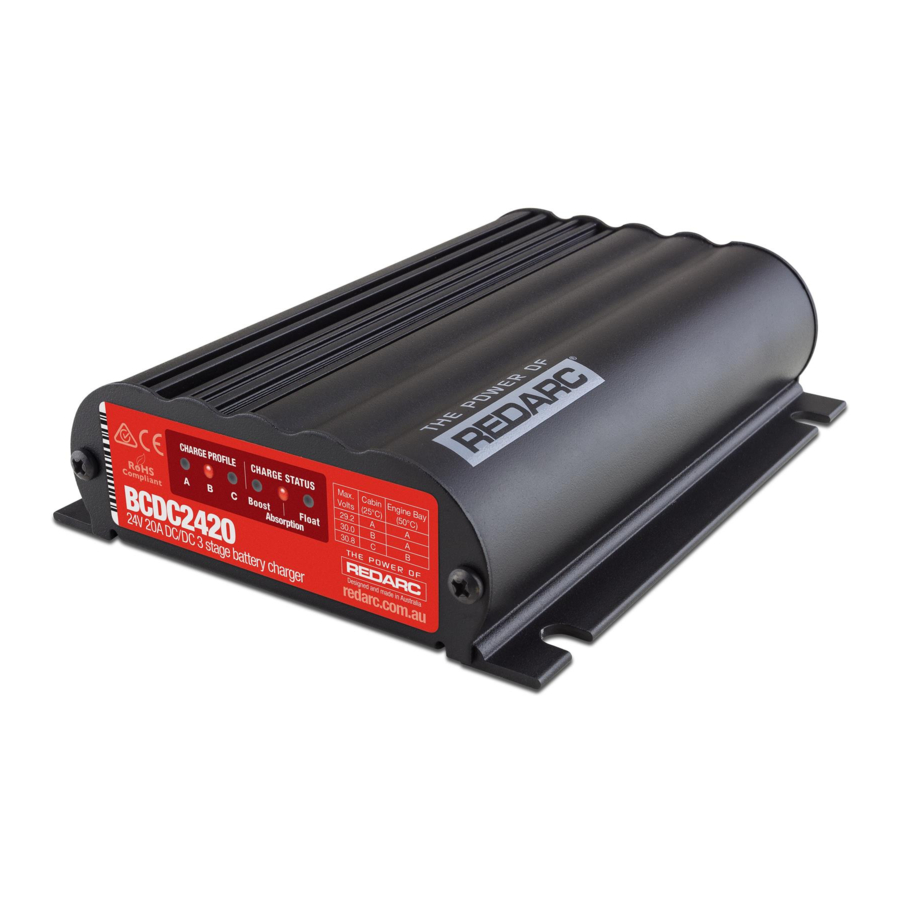
PRODUCT OVERVIEW

The BCDC2420(-LV) In-vehicle Battery Chargers feature technology designed to charge your lead-acid batteries to 100%, regardless of their type or size. By providing a unique charging profile to each specific battery type, the BCDC2420(-LV) In-Vehicle Battery Chargers are able to achieve and maintain an optimal charge in your auxiliary battery, at all times. The BCDC2420(-LV) In-vehicle
Battery Chargers also feature a Maximum Power Point Tracking (MPPT) solar regulator, allowing you to deliver the maximum amount of power from your solar panels to your auxiliary battery. The BCDC2420 is designed to work with either fixed voltage or temperature compensating alternators while the BCDC2420-LV is designed to operate with 12V variable voltage alternators.
WARNINGS AND SAFETY INFORMATION
SAVE THESE INSTRUCTIONS — This manual contains important safety instructions for the BCDC2420(-LV) battery charger.
Do not operate the battery charger unless you have read and understood this manual and the charger is installed as per these installation instructions. REDARC recommends that the charger be installed by a suitably qualified person.
Disclaimer: REDARC accepts no liability for any injury, loss or property damage which may occur from the improper or unsafe installation or use of its products.
SAFETY MESSAGE CONVENTIONS

Safety messages in this manual include a signal word to indicate the level of the hazard as follows: Indicates a potentially hazardous situation which could result in death or serious injury to the operator or to bystanders.

Indicates a potentially hazardous situation which may result in moderate or minor injury to the operator or to bystanders.
 NOTICE: Indicates a situation that may cause equipment damage.
RISK OF EXPLOSIVE GASES: working in vicinity of a lead-acid battery is dangerous. Batteries generate explosive gases during normal operation. For this reason, it is of utmost importance that you follow the instructions when installing and using the charger.
- The Battery Charger should not be used by persons (including children) with reduced physical, sensory or mental capabilities, or lack of experience and knowledge, unless they are supervised or have been instructed on how to use the appliance by a person responsible for their safety. Children should be supervised to ensure that they do not play with the Battery Charger.
- Do NOT alter or disassemble the Battery Charger under any circumstances. All faulty units must be returned to REDARC for repair. Incorrect handling or reassembly may result in a risk of electric shock or fire and may void the unit warranty.
- Only use the Battery Charger for charging Standard Automotive Lead Acid, Calcium Content, Gel, AGM, SLI, or Deep Cycle type 12 V batteries.
- Check the manufacturer's data for your battery and ensure that the 'Maximum' voltage of the profile you select does not exceed the manufacturer's recommended maximum charging voltage. If the 'Maximum' voltage is too high for your battery type, please select another charging profile.
- Check the manufacturer's data for your battery and ensure that the 'Continuous Current Rating' of the charger does not exceed the manufacturer's recommended maximum charging current.
- The Battery Charger is not intended to supply power to a low voltage electrical system other than to charge a battery.
- Cable and fuse sizes are specified by various codes and standards which depend on the type of vehicle the Battery Charger is installed into. Selecting the wrong cable or fuse size could result in harm to the installer or user and/or damage to the Battery Charger or other equipment installed in the system. The installer is responsible for ensuring that the correct cable and fuse sizes are used when installing this Battery Charger.
- NEVER smoke or allow a spark or flame in vicinity of battery or engine. This may cause the battery to explode.
PERSONAL SAFETY PRECAUTIONS
- To assist with the safe operation and use of the Battery Charger when connected to the battery:
- Wear complete eye protection and clothing protection. Avoid touching eyes while working near a battery.
- If battery acid contacts your skin or clothing, remove the affected clothing and wash the affected area of your skin immediately with soap and water. If battery acid enters your eye, immediately flood the eye with running cold water for at least 10 minutes and seek medical assistance immediately.
SPECIFICATIONS
| Part Number | BCDC2420 and BCDC2420-LV | ||
| Continuous Current Rating | 20 A | ||
| Input Current Limit | 32 A | ||
| Input Fuse Rating 12 V/24 V | 60 A / 40 A (Not supplied) | ||
| Output Fuse Rating | 30 A (Not supplied) | ||
| Output Power | 600 W | ||
| DC Input Voltage Range | 9 – 32 VDC ⎓ (9 – 16 VDC ⎓ for LV model) | ||
| Solar Panel Open Circuit Voltage | 17.5 V – 28 V | ||
| Output Battery Type | Standard Lead Acid, Calcium content, Gel & AGM type | ||
| Charging Profile | A | B | C |
| Maximum Voltage (refer to 2.3) | 29.2 V | 30 V | 30.8 V |
| Float Voltage | 26.6 V | ||
| No Load Current | <100mA | ||
| Standby Current | <8mA | ||
| Ambient Temperature | −20°C to +80°C (−4°F to +176°F) | ||
| Maximum O/P Battery Volts | 4.2 V | ||
| Weight | 680 g / 24 oz | ||
| Dimensions | 150 × 120 × 37 mm (5.9 × 4.7 × 1.5") | ||
| Warranty | 2 Years | ||
| Standards | CE,C-Tick, AS/NZS CISPR11:2004 | ||
PRODUCT FUNCTION
The BCDC2420(-LV) is a three-stage, 24 V DC-DC battery charger that operates from an alternator input of 12 V nominal or a 12 V nominal solar panel input. The BCDC2420 will also charge from an alternator input from a 24 V nominal vehicle*1. The input voltage of the BCDC2420(-LV) can be above, below or equal to the output voltage making it ideal for charging an auxiliary 24 V battery bank where the distance from the main battery may cause a significant voltage drop.
The BCDC2420(-LV) is also designed to isolate the main battery from the auxiliary battery to avoid over-discharging the main battery. The BCDC2420-LV operates almost identically to the BCDC2420 but is designed to operate from an ignition trigger to allow operation in vehicles with Variable Voltage or Smart Alternators.
*1 LV Versions are not suitable for use in 24 V vehicles.
DISPLAY PANEL
The front panel features 6 LEDs to display the charge profile and charge status.

When blinking, the flash duty-cycle of the 'Charge Status' LED will increase to reflect the amount of current being supplied - If the LED is ON solid, the unit is supplying full power (e.g. 20 A for a BCDC2420).
| LED State | 'Charge Profile' LED | 'Charge Status' LED |
Off  | Unit has no Power | Output is Off |
Blinking  | Unit is in Standby | Unit is supplying power |
On  | Unit is on and can supply power |
CHARGING PROCESS
BOOST
The Boost stage maintains a constant current until the battery voltage reaches its Absorption Voltage. The current in Boost stage may vary during operation in order to maintain safe operating temperature, or to limit the difference between input and output voltages.
ABSORPTION
The Charger will then move to Absorption stage which maintains a constant voltage level for a predetermined period of time or until the current being drawn by the output battery drops to less than 4 A for 30 seconds; after which the Charger will enter Float stage.
FLOAT
Float stage maintains 13.3 V on the output battery, keeping the battery topped up. This counteracts the battery's self discharging or loads applied to the battery. When the battery loses charge, the Charger will automatically move back into the Boost stage.

Figure 1: Charging Process
The BCDC has automatic Timeouts to protect the battery from being damaged by overcharging. The BCDC will automatically move from Boost to Absorption or Float according to these timeouts. If a Timeout occurs before the battery is fully charged, the charge process will begin again from the Boost stage after a brief 'rest-period'.
TURN ON/OFF THRESHOLDS
| 12 V BCDC2420 | 12 V BCDC2420-LV | Solar All Models | 24 V (standard)*3 BCDC2420 | ||
| Input Open Circuit Low voltage conditions*1 | Turn ON ABOVE | 12.9 V | 12.0 V | 17.5 V | 26.4 V |
| Turn OFF BELOW | 12.7 V | 11.9 V | 17.2 V | 25.4 V | |
| Input Loaded Low voltage conditions*2 | Turn OFF instantly BELOW | 8.0 V | 17.0 V | ||
| Turn OFF after 20 s BELOW | 9.0 V | N/A | 18.0 V | ||
| Input Over voltage shutdown | Turn ON BELOW | 15.5 V | 28.0 V | 32.0 V | |
| Turn OFF instantly ABOVE | 16.0 V | 29.0 V | 32.5 V | ||
| Turn OFF after 20 s ABOVE | 15.6 V | 28.2 V | 32.1 V | ||
| Output Under voltage shutdown*1 | Shutdown if Output Battery < 4 V | ||||
*1 Tested every 100 seconds
*2 Tested constantly
*3 LV Versions not suitable for use in 24 V vehicles.
ERROR CODES
In the event of a fault with the unit installation, either battery or solar panel, ALL the LEDs on the unit will flash to indicate the fault type. Flashing sequences are described in the table below.
Table 1: Flashing Sequences
| LED State | Description |
| 1 flash (1 flash followed by 3.5 second off) | Internal Hardware Fault |
| 2 flash (2 flash followed by 3.5 second off) | Reserved |
| 3 flash (3 flash followed by 3.5 second off) | Unit over temperature fault |
| 4 flash (4 flash followed by 3.5 second off) | Output battery fault (volts too high) / solar panel connected reverse polarity) |
| 5 flash (5 flash followed by 3.5 second off) | Input under voltage (battery) |
| 6 flash (6 flash followed by 3.5 second off) | Input over voltage (battery or solar panel) |
| 7 flash (7 flash followed by 3.5 second off) | Reverse polarity |
INSTALLATION
INSTALL LOCATION

Figure 2: Mounting the Charger
Mount the unit to a flat surface close to the auxiliary battery and away from any heat sources. The BCDC2420(-LV) has six wires and should be installed as described over the following pages.
The charger operates in any orientation (but it is recommended that the front of the decal be visible). Mount using the 4 mounting tabs provided on the heatsink with suitable M6 fasteners.
NOTE: The unit will operate optimally below 55°C / 131°F with good airflow. At higher temperatures the unit will de-rate output current.
NOTE: Appropriate connections must be made to the wires with a continuous current rating of at least 20 A for the BCDC2420(-LV). Failure to do so may cause damage to the unit and vehicle.
CABLE SIZING
Below is a table outlining the required cable size for a given cable install length. Always choose a wire diameter equal to or greater than what is specified below.
Table 2: Recommended Cable Sizing
| Cable Install Length | Recommended Wire Size | Closest (BAE, B&S, AWG) | |
| 1 – 5 m | 3 – 16' | 13.56 mm2 | 6 |
| 5 – 9 m | 16 – 30' | 20.28 mm2 | 4 |
FUSING
REDARC recommends using MIDI style bolt down fuses as they ensure a low resistance connection. The REDARC FK40 and FK60 fuse kits are recommended.
Blade type fuses are not recommended as they can result in a high resistance connection which causes excess heat and may damage the fuse holder and/or the wiring. Self-resetting circuit breakers are not recommended as they may trip prematurely due to the heat generated by the current flowing through the wires.

Figure 3: MIDI Style Bolt-Down Fuse

Figure 4: MIDI Fuse Assembly
WIRE CONNECTIONS
Cable and fuse sizes are specified by various codes and standards which depend on the type of vehicle the Battery Charger is installed into. Selecting the wrong cable or fuse size could result in harm to the installer or user and/or damage to the Battery Charger or other equipment installed in the system. The installer is responsible for ensuring that the correct cable and fuse sizes are used when installing this Battery Charger. Cabling is recommended to be away from heat sources and in protected areas, especially when installing or routing in the engine bay.
The heavy gauge wires on the BCDC2420(-LV) unit carry peak currents of up to 40 Amps, and it is important to make a good, low resistance, electrical connection that will not degrade over time. Failure to make a good, reliable contact may result in breakdown of the wire insulation and cause a short circuit, or worst case a fire. We recommend that this activity be undertaken by an appropriately trained person.
REDARC recommends using a soldered butt splice crimp connection that is covered with heatshrink (see Figure 5).
Figure 5: Ensuring a good wiring connection

Crimp both wires to the butt splice using single-indent type crimpers. Fold the cable over before inserting into the butt-splice as required. Single-indent crimpers should also be used on any lugs used.

Solder the wires to the butt splice. Ensure that a good connection is made. Keep heatshrink away until after soldering is complete and has cooled.
REDARC does not recommend using standard red/ blue/yellow blade connections as they are not rated for either the current required or gauge of wire supplied on the unit. Crimping provides good mechanical connection, soldering provides a long lasting electrical connection and forming of the heatshrink will prevent any shorting/contact with your vehicle chassis.
AUXILIARY BATTERY POSITIVE — BROWN WIRE
Figure 6: Connecting the BROWN wire

The BROWN wire should be connected to the auxiliary battery's positive terminal. This should be a maximum of 1 m (3') in cable length from the battery. See "Specifications" for appropriate size fuses.
COMMON GROUND — BLACK WIRE
Figure 7: Connecting the BLACK wire

The BLACK wire should be connected to a ground point that is common to both the start battery (or the solar input ground wire) and the auxiliary battery to be charged. This point may be on the chassis of the vehicle, the chassis of the trailer/camper/caravan or directly to both batteries, depending on your installation requirements.
INPUT SOURCE POSITIVE — RED WIRE
The RED wire should be connected to the positive input from the source — this can be either from a vehicle's starter battery or from a solar panel. See "Specifications" for appropriate size fuses.
Figure 8: Connecting the RED wire

Vehicle Start Battery

Solar Panel
SOURCE SELECT — BLUE WIRE
The BLUE wire is provided to select whether the Unit is charging from a vehicle input or from a solar panel. This wire is monitored at all times.
ALTERNATOR INPUT
For BCDC2420 (not 'LV' models), the BLUE wire must be permanently connected to the Input Source Positive supply and the charger will only charge when the alternator is running. This is not suitable for the BCDC2420-LV.
To charge from 12 V Variable Voltage alternator, the BLUE 'Source Select' wire must be connected to the vehicle ignition. When connected in this way, the charger will only charge the auxiliary battery when the vehicle ignition is ON, guaranteeing that the charger will not drain the input battery.

Do NOT connect the BLUE wire to ignition for a 24 V alternator system.
Figure 9: Connecting the BLUE wire to alternator input
")
Input Source Positive (BCDC2420 only)

Vehicle Ignition (12 V only)
SOLAR INPUT
The BCDC2420 is also capable of charging the auxiliary battery from a Solar source. The Unit will accept an input directly from an unregulated 12V nominal solar panels and act as a MPPT Solar Regulator. To select the Solar charging mode, the BLUE 'Source Select' wire can either be left disconnected or connected to GROUND.
Figure 10: Connecting the BLUE wire to solar panel

Connected

Not Connected
BATTERY TYPE SELECT — ORANGE WIRE
The ORANGE wire is used to select the Maximum output voltage. This is achieved by connecting in the following way:
Figure 11: Setting the Maximum Voltage (ORANGE wire)
| PROFILE A Leave the ORANGE wire disconnected to set the Maximum voltage to 29.2 V. |  | ||
| PROFILE B Connect the ORANGE wire to Common Ground to set the Maximum voltage to 30.0 V. |  | ||
| PROFILE C Connect the ORANGE wire to the RED wire (Input source positive) to set the Maximum voltage to 30.8 V. |  |
Check the manufacturer's data for your battery and ensure that the Maximum voltage of the Charging Profile you select does not exceed the manufacturer's recommended maximum charging voltage. If the Maximum voltage is too high for your battery type, select another Charging Profile.
Table 3: Charge Profile Selection
| Maximum Battery Voltage Specification | Auxiliary Battery Location | ||
| Cabin Install (25°C/75°F) | Engine Bay Install (50°C/120°F) | ||
| 29.2 V | A | A | |
| 30 V | B | A | |
| 30.8 V | C | B | |
OPTIONAL EXTERNAL LED INDICATION — GREEN WIRE
The GREEN wire is provided to optionally connect an external indicator LED to function as an indicator to let you know the BCDC is charging. The External LED will be ON when the unit is charging and OFF when the unit is in standby mode or has no power.
Figure 12: Connecting the GREEN wire

Connect the positive lead of the LED to the green wire, and the negative lead to the common ground.
NOTE: If using an Optional LED, use a standard 12 V LED with an integrated resistor (12 V = 1kΩ or 24 V = 2.2 kΩ). A basic 3 V LED will not operate correctly if installed.
NOTE: This output is not suitable for running a globe.
TYPICAL SETUPS
REDARC recommends that the charger be installed by a suitably qualified person.
Figure 13: BCDC2420 Standard Setup for a 12 V or 24 V Start Battery

Figure 14: BCDC2420-LV Standard Setup for a 12 V Start Battery

*1 Fuse ratings as shown in "Specifications".
*2 For vehicle ignition connection, connect to the ignition switched fuse in either the engine bay or the internal fuse box for the radio.
*3 If using an Optional LED, use a standard 12 V LED with an integrated resistor (12 V = 1kΩ or 24 V = 2.2 kΩ). A basic 3 V LED will not operate correctly if installed.
*4 For Charging Profile Select, refer to 'Table 3: Charge Profile Selection' .
Figure 15: Both Models Standard Setup for a 12 V Solar Array

Figure 16: Both Models Standard Setup for a 12 V Solar Array

*1 Fuse ratings as shown in "Specifications".
*2 For vehicle ignition connection, connect to the ignition switched fuse in either the engine bay or the internal fuse box for the radio.
*3 If using an Optional LED, use a standard 12 V LED with an integrated resistor (12 V = 1kΩ or 24 V = 2.2 kΩ). A basic 3 V LED will not operate correctly if installed.
*4 A relay suitable for 12 V Vehicle installations is available as part of the REDARC RK1260 Relay Kit. The kit also includes buttsplice connectors, a wiring loom, heat shrink and instructions.
*5 For Charging Profile Select, refer to 'Table 3: Charge Profile Selection').
TROUBLESHOOTING

FREQUENTLY ASKED QUESTIONS
The BCDC2420(-LV) turns ON at 12.9 V (12 V) and OFF at 12.7 V (11.9 V), but you say it operates down to 9 V, explain?
The BCDC2420(-LV) will turn OFF for a split second every 100 seconds to measure the unloaded voltage at the battery. When the BCDC2420(-LV) turns off it is not drawing any load from the start battery, no load means that there is no voltage drop over the cable run.
This allows the BCDC2420(- LV) to measure the actual battery voltage, or the voltage at the battery. If this actual battery voltage is below 12.7 V (11.9 V), the BCDC2420(-LV) will turn OFF. At any other time during the charging process, if the voltage at the BCDC2420(-LV) drops below 9 V the BCDC2420(-LV) will turn OFF.
How does the BCDC charge an auxiliary battery at 29 V when it only gets 9 V in?
The BCDC can act as both a reducer and a booster, so it can operate from a voltage of above, equal to or below the desired output voltage. The Unit is also microprocessor controlled allowing it to output a REDARC proprietary charging algorithm independent of the input. This allows the Unit to charge specificity to the battery type even if the input voltage is low due to voltage drop.
Where should I mount the BCDC Unit?
The BCDC should be mounted as close as possible to the battery being charged (generally called the auxiliary or house battery). If the auxiliary battery is located under the bonnet, pick a location for the BCDC that is close to the battery and away from any direct engine heat. If the BCDC is to be mounted into a caravan or camper, near or in the battery compartment is generally the best position. It is also a good idea to mount the BCDC to a metal surface if possible to ensure optimal heat dissipation, though this is not crucial.
What does the charger do if the temperature around it rises above its operating temperature?
As the temperature of the BCDC rises above a certain level the current capacity of the output is decreased gradually in order protect both the battery and the BCDC Unit.
If I use the BCDC to charge my auxiliary battery do I still need to install a battery isolator?
The BCDC incorporates the functionality of a battery isolator, it will turn ON and start charging when it senses that the vehicle has started and similarly it will turn OFF when the vehicle is turned OFF.
I've heard that you shouldn't charge two batteries of different chemistries from the same source, will I have any problems charging my AGM or Gel auxiliary battery from my Lead Acid start battery?
The BCDC does not 'link' the batteries together like a battery isolator does, it is a DC-DC battery charger. The output from the unit is tailored specifically to the selected output battery type, and therefore allows the optimal charging of the auxiliary battery, no matter what chemistry your start battery is.
My BCDC is setup for 12 V alternator input but will not start when the vehicle is turned ON, I've followed the troubleshooting guide and the setup is fine, what's the problem?
The most likely cause of this issue is that the BCDC is somehow 'stuck' in 24 V mode. Try removing the 'Source Select' (BLUE) wire and reconnecting it. If the problem still exists please contact REDARC Tech Support power@redarcelectronics.eu

Documents / ResourcesDownload manual
Here you can download full pdf version of manual, it may contain additional safety instructions, warranty information, FCC rules, etc.
Download REDARC BCDC2420, BCDC2420-LV - In-Vehicle 3-Stage 24V DC Battery Charger Manual
Advertisement


Need help?
Do you have a question about the BCDC2420 and is the answer not in the manual?
Questions and answers