Table of Contents
Advertisement
Advertisement
Table of Contents

Related Manuals for Redarc The Manager30


Summary of Contents for Redarc The Manager30
- Page 1 MANAGER Battery Management System BMS1230S3-NA...
-
Page 2: Warnings & Important Safety Instructions
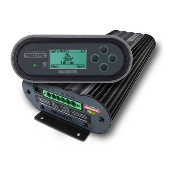
THE MANAGER30 The Manager30 Battery Management System is a complete charging solution for your Lead Acid or Lithium Iron Phosphate (LiFePO Auxiliary or House battery. The system incorporates 12 V Solar, 110 VAC and 12/24 VDC inputs to provide a 12 V charging output at a maximum 30 A rating. - Page 3 WARNINGS AND SAFETY INSTRUCTIONS battery to spark or might short-circuit the battery or other eye, immediately flood the eye with running cold water for at electrical parts that may cause an explosion. least 10 minutes and seek medical assistance immediately. e) To improve user safety it is recommended to control the 12.
-
Page 4: Table Of Contents
2.4.1 Load Disconnect Feature 2.4.2 Ignition Trigger Feature 2.4.3 Connecting the Battery Sensor 2.4.4 Wiring the Main Unit Batteries MPPT Solar Regulator Copyright © 2020 REDARC Electronics Pty Ltd. All rights reserved. Design and specifications are subject to change without notice. -
Page 5: Features And Benefits
FEATURES AND BENEFITS 1. The Manager30 incorporates six products in one, it’s a DC–DC charger, a 110 VAC Mains/Shore Power charger, a solar charger, a dual battery isolator, a load disconnect controller and a remote battery monitor. The Manager30 will automatically select between charging sources, requiring no input from the operator during its operation. -
Page 6: Introduction
The Manager30 is designed to offer a complete solution to battery charging and maintenance needs for recreational automotive applications. The Manager30 incorporates AC Mains/Shore Power, DC and Solar inputs to achieve the best charge to a house battery. The Remote Monitor The Manager30 comes with a Remote Monitor designed to give you house battery information and charge status along with critical system information while charging is in progress. -
Page 7: Specifications
INTRODUCTION Specifications Electrical Specifications Inputs AC Input Input Voltage Range (nominal) 110 to 120 VAC, 50 to 60 Hz Power Rating 560 W Efficiency 80% to 90% Connection IEC Mains Plug DC Input Input Voltage Range 9 to 30 VDC Turn ON/OFF Threshold 12 V (24 V) 13.2 V / 12.7 V (26.4 V / 25.4 V) Power Rating 520 W... - Page 8 INTRODUCTION 17.520" (445 mm) 15.906" (404 mm) 16.890" (429 mm) FIGURE 1.4.1: Main Unit Dimensions 7.323" (186 mm) 1.063" (27 mm) FIGURE 1.4.2: Remote Monitor Dimensions...
-
Page 9: Multi-Stage Charging Process
This allows The Manager30 to operate correctly even when loads are connected to the house battery. This mode will always produce an output (unless a fault condition is detected) and will cycle through the three stages as required to maintain the house battery as outlined in Figure 1.5.1. - Page 10 Valid charging sources for The Manager30 while in Storage mode include AC Shore Power and Solar. NOTE: If The Manager30 is set to Storage mode and the vehicle is started The Manager30 will automatically switch to Touring mode once it senses an increase in input voltage from the alternator.
-
Page 11: Maximum Charge Current Setting
30 Amps, the current supplied to charge the battery is restricted to the user setting. Any excess current is available to power loads running from the battery under charge. If no loads are running from the battery, total current from The Manager30 will be restricted to the level set by the user. -
Page 12: Installation Guide
BMS1230 Monitor 110 VAC Mains/Shore Power FIGURE 2.1.1: System Layout Mounting Instructions This section describes how to mount the three major components of The Manager30: the Main Unit, the Remote Monitor and the Battery Sensor. FIGURE 2.2.1: The Manager30 System... -
Page 13: Mounting The Main Unit
2.2.1 Mounting the Main Unit Do NOT expose the Main Unit to rain, snow, spray or bilge water. For optimum operation, The Manager30 should be mounted where the temperature is nominally below 95 °F (35 °C) and does not exceed a maximum of 140 °F (60 °C). -
Page 14: Mounting The Remote Monitor
INSTALLATION GUIDE 2.2.2 Mounting the Remote Monitor The Remote Monitor should be mounted inside the travel trailer or RV using the template provided on page 37. It is acceptable however to mount the Remote Monitor in any convenient location, as long as it is protected from harsh environments. - Page 15 INSTALLATION GUIDE Wall Mount Use the template provided (section 4 on Attach the Back Plate to the wall using 4 page 37) to mark the position and drill and suitably sized countersunk screws. cut the mounting holes into the wall. Feed the Remote Monitor cable through the Clip the Inner Assembly into the Back Plate.
- Page 16 INSTALLATION GUIDE Removing the Remote Monitor The locking tabs on the back of the Inner The locking tabs can be accessed through Assembly need to be unclipped from the Back holes on the top of the backing plate when Plate. installed.
-
Page 17: Mounting The Battery Sensor
Battery Charger. The Manager30 is capable of drawing up to 50 A from the Vehicle Battery (which may be several feet/ meters from its installation location) and is limited to 30 A output to the House Battery. The installer needs to ensure the appropriate cable is used to connect the positive and negative connections of The Manager30 to both the Vehicle Battery and the House Battery. -
Page 18: Input Wire Diameter Selection
2.3.2 Output Wire Diameter Selection REDARC recommends the installer use cabling and connections between 8B&S and 6B&S automotive. REDARC recommends that the output wire be of the size outlined in Figure 2.3.2.1. For longer runs, using 6B&S (13 mm ) is recommended, however this will lower efficiency by up to 3% (the recommended maximum length is 16'5"... -
Page 19: The Manager30 Wiring Connections
Manager30 AC input if the cord is damaged. Use of a non-genuine or damaged AC input cord may result in a risk of fire, electric shock, or injury to persons. (If the supply cord is damaged, it must be replaced by the genuine REDARC part or assembly available from the manufacturer or service agent). CAUTION Always wire the Output Connector before connecting it to the Main Unit. -
Page 20: Connecting The Battery Sensor
INSTALLATION GUIDE 2.4.3 Connecting the Battery Sensor Wire the Battery Sensor as shown in Figure 2.4.3.1 ensuring that the Voltage and Temperature Sensor (RED terminal) connects to the house battery positive terminal. This lead measures voltage and temperature at the battery. The “BNEG” stud connects to the House Battery negative terminal and the “GND”... - Page 21 (Red terminal) on the House Battery Sensor is Battery, and should be rated slightly higher than connected to the House Battery Positive Terminal. this. REDARC recommend the use of MIDI Style Fuses. A single fuse and holder *2 Essential loads are loads which must be left on setup from the Fuse Kits at all times, until the battery is flat.
-
Page 22: Batteries
Noticeable oscillations between Boost and Absorption stages indicate incorrect choice of battery type. Check and adjust battery type. If you are unsure of the battery type or settings to use, set The Manager30 to the Gel profile. -
Page 23: Mppt Solar Regulator
(Refer to Figure 2.6.1). So long as the voltage requirements are met, there is no limit to the number of panels that can be connected in a solar array; however The Manager30 will not draw more than 520 W from the solar input. -
Page 24: User Guide
USER GUIDE Remote Monitor The Remote Monitor is designed to give you control of how the battery is being charged, as well as up- to-date house battery and charge information at any time during the charging process. You can check battery charge status, estimated charge time and State of Charge (SoC) per hour over a day and per day over a month. -
Page 25: Initial Setup
USER GUIDE Initial Setup When The Manager30 is first switched on the unit will prompt the user to enter a number of settings. It is important to enter these settings accurately as they directly affect the operation and performance of The Manager30. -
Page 26: User Menu
USER GUIDE User Menu The Manager30 features a real time clock (time and date) function which needs to be setup when the power is first connected. Set the Time and Date Charging Status Screen Battery Charge Screen The Manager30 monitors current in and out of the house battery, keeping track of the charge remaining. - Page 27 The Output Status screen displays a summary of the current flow of the system. The screen will display current from The Manager30 unit, current in to or out of the battery and current provided to the loads. The direction of the current flow is indicated by the arrows, and a moving white dot.
-
Page 28: Settings Menu
The Manager30 to indicate a fault or give misleading results and could result in damage to the battery. Noticeable oscillations between Boost and Absorption stages indicate the wrong choice of battery type. Check and adjust battery type. If you are unsure of the battery type or settings to use, set The Manager30 to the Gel setting. - Page 29 Restore Factory Settings Screen NOTICE Modification of the ‘Advanced Settings’ menu items affect the way The Manager30 unit responds to charging situations. Modification of these settings may result in the unit not functioning at 100% of its capacity. These settings should only be modified if absolutely necessary and when the effects of the...
- Page 30 USER GUIDE The MaxCharge Current setting refers to the amount of current permitted by The Manager30 to charge the battery, up to a maximum of 30 Amps. Set Charging Current Screen R-Bus Diagnostics Screen Advanced Settings Screen Low SoC Alarm Screen If the Charging Current setting is set lower than 30 Amps the excess current will be used to supply the loads running from the battery under charge.
- Page 31 Load Temporarily Connected The DC Input Trigger allows you to select whether you would like your DC input to be triggered via Ignition, automatically via The Manager30, or at a specific voltage. Set DC Input Trigger Screen Load Disconnect Screen...
-
Page 32: Fault Screens
Set DC Input Trigger Screen Advanced Settings Screen MaxCharge Current Screen This screen gives the option of restoring the Factory Settings for The Manager30. A list of the factory settings can be found in section 3.8. Restore Settings/ Confirm Advanced Settings Screen... -
Page 33: Troubleshooting
Ignore Fault Troubleshooting The Manager30 is designed to detect and advise the operator of a variety of fault conditions and will terminate the charging cycle immediately should a critical fault be detected. This ensures that it will not attempt to charge a faulty battery, which protects The Manager30, house battery and most importantly the user. -
Page 34: Faults
USER GUIDE 3.7.1 Faults CHARGER FAULT MESSAGE CAUSE ACTION Charger over current fault An internal error has caused excessive Return to supplier current draw Charger over voltage fault The output voltage is too high (above Check battery is correct type (12 V, 6 cell) 18 V) Unit over temperature fault. -
Page 35: Factory Settings
USER GUIDE Factory Settings The Manager30 is shipped with a number of settings already programmed into the unit. These settings are set to ensure that the charger will safely charge any battery and may not reflect the actual requirements for your battery type. It is important to review these settings and adjust as required. -
Page 36: Frequently Asked Questions
REDARC cord available from the manufacturer. I am running a load from my house battery, but it does not seem to register on The Manager30 Remote, why can I not see this current draw? This is generally caused by incorrect wiring of the Battery Sensor. -
Page 37: Remote Drill Template
REMOTE DRILL TEMPLATE ⌀0.17" 1.95" (49.5 mm) (4.4 mm) ⌀1.95" (49.5 mm) PHOTOCOPY OR PRINT THIS PAGE AT 100% SCALE Before drilling holes, ensure that this template is printed at the correct size. Cut/drill the red line. 2.91" (74 mm) -
Page 38: Notes
NOTES... -
Page 39: Two-Year Product Warranty - North America
24 for prompt and efficient diagnosis and product support. REDARC Corporation Pty Ltd (“REDARC”) offers a warranty in respect of its Products purchased from an authorized distributor or reseller of REDARC by a person who is the original retail purchaser (“Purchaser”), on the terms and conditions, and for the duration, outlined below in this document (“Warranty”). - Page 40 FREE TECHNICAL ASSISTANCE For product and technical support contact your regional distributor, call our head office between 8:00 a.m. to 5:30 p.m. Australian Central Standard Time, Monday to Friday, or send us an e-mail. Pour accéder Para ver el au manuel manual en d’utilisation Español...
Need help?
Do you have a question about the The Manager30 and is the answer not in the manual?
Questions and answers