Table of Contents
Advertisement
Advertisement
Table of Contents

Summary of Contents for Redarc LFP1225
-
Page 1: Battery Charger
In-vehicle 12V LiFePO4 Battery Charger LFP1225, LFP1225-LV, LFP1240 & LFP1240-LV... - Page 2 Ensure that the battery management system is capable of allowing the battery to be charged with 25A for the LFP1225(LV) or 40A for the LFP1240(LV). Please contact REDARC if you are unsure if your battery is compatible. The LFP1225(LV)/LFP1240(LV) will achieve best results when proper battery maintenance is regularly performed.
-
Page 3: Table Of Contents
Cable Sizing Wiring RK1260 Relay Kit 3 Troubleshooting 4 Frequently Asked Questions 5 Two Year Warranty Specifications Part Number LFP1225(LV) LFP1240(LV) Continuous Current Rating Input Fuse Rating 40A (Not Supplied) 60A (Not supplied) REDARC FK40 REDARC FK60 Output Fuse Rating... -
Page 4: Product Function
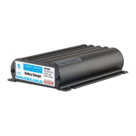
The LFP1225(LV)/LFP1240(LV) is a two stage, 12V DC-DC battery charger that operates from an alternator input of 12V nominal or a 12V nominal solar panel input. The LFP1225/ LFP1240 will also charge from an alternator input of a 24V nominal vehicle* . -
Page 5: Charging Algorithm
PRODUCT FUNCTION Charging Algorithm When the LFP1225(LV)/LFP1240(LV) is turned on, it will move into the Constant Current stage. This stage maintains a constant current until the battery voltage reaches its set point. The current may vary during operation in order to maintain safe operating temperature, or to limit the difference between input and output voltage. -
Page 6: Error Codes
NOTE: Appropriate connections must be made to the wires with a continuous current rating of at least 25A for the LFP1225(LV) or 40A for the LFP1240(LV). Failure to do so may cause damage to the unit and vehicle. - Page 7 For standard (non ‘LV’) models, the BLUE wire may models only Red Wire be permanently connected to the 12v supply and the charger will only charge when the alternator is running. This is not suitable for the LFP1225-LV or LFP1240-LV. Input Source Positive 1.1.2 Solar Input...
-
Page 8: Orange Wire - Not Used
PRODUCT FUNCTION ORANGE wire - Not Used Connected The ORANGE wire is not used on the LFP series chargers. It should be left disconnected. Orange Wire BROWN wire - Auxiliary Battery Positive Brown Wire The BROWN wire should be connected to the auxiliary battery’s positive terminal. -
Page 9: Cable Sizing
20.28 Wiring The heavy gauge wires on the LFP1225(LV) and LFP1240(LV) unit carry peak currents of up to 35 and 50 Amps respectively, and it is important to make a good, low resistance, electrical connection that will not degrade over time. Failure to make a good, reliable contact may result in breakdown of the wire insulation and cause a short circuit, or worst case a fire. - Page 10 Battery LFP1225 & LFP1240 *Fuse Ratings as per table on Page 2 Figure 2.8a - LFP1225 and LFP1240 Standard setup for a 12V Start Battery Note: Power wires must be at least 6mm² and must be crimped using an INPUT appropriate crimp tool.
- Page 11 Not Used (Leave Disconnected) Start All ground points must Battery be connected to chassis Auxiliary earth. Battery LFP1225 & LFP1240 *Fuse Ratings as per table on Page 2 Figure 2.8d - LFP1225 and LFP1240 Standard setup for a 24V Start Battery...
-
Page 12: Rk1260 Relay Kit
The below diagram shows a changeover relay being controlled by vehicle ignitions to automatically swap between alternator and solar panel inputs. A Relay suitable for 12V Vehicle installations is available as part of the REDARC RK1260 Relay Kit. The kit also includes butt-splice connectors, a wiring loom, heat shrink, and instructions. -
Page 13: Troubleshooting
4v? system or contact REDARC If the battery voltage is Electronics for more information. still low, replace battery. Figure 3.1 - Standard LFP1225(LV)/LFP1240(LV) Troubleshooting Guide... -
Page 14: Frequently Asked Questions
How does the LFP1225(LV)/LFP1240(LV) charge an Auxiliary battery at 14V when it only gets 9V in? The LFP1225(LV)/LFP1240(LV) can act as both a reducer and a booster, so it can operate from a voltage of above, equal to or below the desired output voltage. The unit is also microprocessor controlled allowing it to output a REDARC proprietary charging algorithm independent of the input. - Page 15 • Friendly, personalised, professional service and product support In the unlikely event that a technical issue arises with a Redarc product, customers are encouraged to initially contact the Redarc Technical Support Team on (08) 8322 4848 power@redarc.com.au for prompt and efficient diagnosis and product support.
- Page 16 Free technical assistance! please contact REDARC Electronics 23 Brodie Road North, Lonsdale SA (08) 8322 4848 power@redarc.com.au www.redarc.com.au Copyright © 2015 REDARC Electronics Pty Ltd. All rights reserved. www.redarc.com.au WARLFP-REV2...


Need help?
Do you have a question about the LFP1225 and is the answer not in the manual?
Questions and answers