Advertisement
PRODUCT OVERVIEW

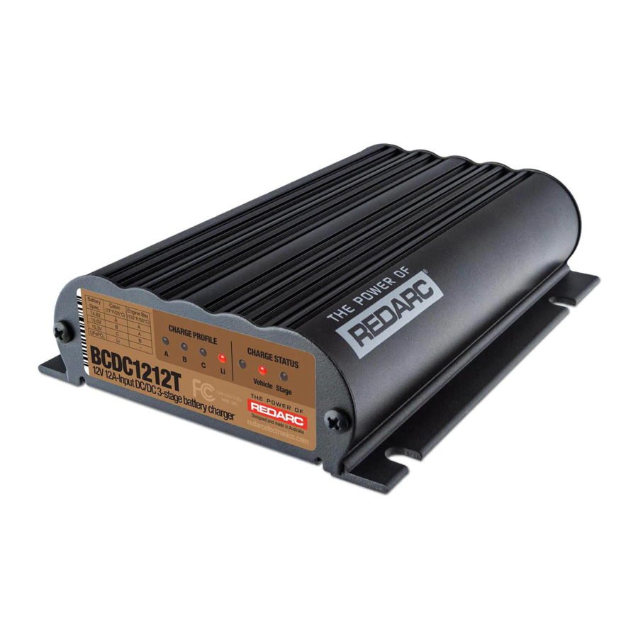
The BCDC1212T In-vehicle Battery Charger features technology designed to charge your auxiliary batteries to 100%, regardless of their type or size. The In-vehicle Battery Charger is suitable for all common types of automotive lead acid batteries and LiFePO4 lithium type batteries.
WARNINGS AND SAFETY INSTRUCTIONS
SAVE THESE INSTRUCTIONS — This manual contains important safety instructions for the BCDC1212T Battery Charger.
Do not operate the Battery Charger unless you have read and understood this manual and the Charger is installed as per these installation instructions. REDARC recommends that the Charger be installed by a suitably qualified person.
SAFETY MESSAGE CONVENTIONS
Safety messages in this manual include a signal word to indicate the level of the hazard as follows:

Indicates a potentially hazardous situation which could result in death or serious injury to the operator or to bystanders.

Indicates a potentially hazardous situation which may result in moderate or minor injury to the operator or to bystanders.
 NOTICE: Indicates a situation that may cause equipment damage.
RISK OF EXPLOSIVE GASES: Working in vicinity of a Lead-Acid battery is dangerous. Batteries generate explosive gases during normal operation. For this reason, it is of utmost importance that you follow the instructions when installing and using the Charger.
- The Battery Charger should not be used by persons (including children) with reduced physical, sensory or mental capabilities, or lack of experience and knowledge, unless they are supervised or have been instructed on how to use the appliance by a person responsible for their safety. Children should be supervised to ensure that they do not play with the Battery Charger.
- Do NOT alter or disassemble the Battery Charger under any circumstances. All faulty units must be returned to REDARC for repair. Incorrect handling or reassembly may result in a risk of electric shock or fire and may void the unit warranty.
- Only use the Battery Charger for charging Standard Automotive Lead Acid, Calcium Content, Gel, AGM, SLI, Deep Cycle or Lithium Iron Phosphate type 12 V batteries.
- Check the manufacturer's data for your battery and ensure that the 'Maximum' voltage of the profile you select does not exceed the manufacturer's recommended maximum charging voltage. If the 'Maximum' voltage is too high for your battery type, please select another charging profile.
- Check the manufacturer's data for your battery and ensure that the 'Continuous Current Rating' of the charger does not exceed the manufacturer's recommended maximum charging current.
- When using the Battery Charger to charge a Lithium Iron Phosphate battery, only batteries that feature an inbuilt battery management system featuring under and over voltage protection and cell balancing are suitable.
- The Battery Charger is not intended to supply power to a low voltage electrical system other than to charge a battery.
- Cable and fuse sizes are specified by various codes and standards which depend on the type of vehicle the Battery Charger is installed into. Selecting the wrong cable or fuse size could result in harm to the installer or user and/or damage to the Battery Charger or other equipment installed in the system. The installer is responsible for ensuring that the correct cable and fuse sizes are used when installing this Battery Charger.
- NEVER smoke or allow a spark or flame in vicinity of battery or engine. This may cause the battery to explode.
PERSONAL SAFETY PRECAUTIONS
- To assist with the safe operation and use of the Battery Charger when connected to the battery:
- Wear complete eye protection and clothing protection. Avoid touching eyes while working near a battery.
- If battery acid contacts your skin or clothing, remove the affected clothing and wash the affected area of your skin immediately with soap and water. If battery acid enters your eye, immediately flood the eye with running cold water for at least 10 minutes and seek medical assistance immediately.
SPECIFICATIONS
| Part Number | BCDC1212T | |||
| Continuous Current Rating | 12 A | |||
| Input Fuse Rating Output Fuse Rating | 15 A to 23 A / 30 A (not supplied) | |||
| Vehicle Input Voltage Range* | 9 to 32 V | |||
| Nominal System Voltage | 12 V | 24 V | ||
| Max. Rated Output Current | 11 A | 20 A | ||
| Nominal Output Power | 147 W | 294 W | ||
| Output Battery Type | Standard Lead Acid, Calcium content, Gel, AGM or LiFePO4 type only | |||
| Charging Profile | A | B | C | Li |
| Maximum Voltage* (refer to Table 2) | 14.6 V | 15.0 V | 15.3 V | 14.5 V |
| Float Voltage *1 | 13.3 V | 13.6 V | ||
| No Load Current | < 100 mA | |||
| Standby Current | < 8 mA | |||
| Minimum O/P Battery Volts | 0.1 V | |||
| Operating Temperature | –15°C to 80°C (5°F to 175°F) | |||
| Charging Temperature | A,B and C - Output Batt. > 10.5 V | –15°C to 80°C (5°F to 175°F) | ||
| A,B and C - Output Batt. < 10.5 V | 0°C to 80°C (32°F to 175°F) | |||
| LiFePO4 | 0°C to 80°C (32°F to 175°F) | |||
| Weight | 850 g (30 oz) | |||
| Dimensions | 165 × 120 × 37 mm / 6.5" × 4.75" × 1.47" | |||
| Warranty | 2 years | |||
| Standards | RCM, FCC, ICESm CE, RoHS, E-Mark | |||
* Voltages Specified are ± 100 mV

PRODUCT FUNCTION
The BCDC1212T is specifically designed for, but not limited to, applications where the input current required to charge a trailer mounted auxiliary battery is drawn through the vehicle's towing harnesses and connectors. It limits the input current drawn to 12 A which provides for safe and reliable operation when using towing harnesses, fuses and connectors that are suitably rated without the need to install additional cables and connectors between the start battery / alternator and the BCDC1212T / auxiliary battery.
The BCDC1212T is a three-stage, 12 V DC-DC Battery Charger that operates from an alternator input of 12 V or 24 V. The input voltage to the BCDC1212T can be above, below or equal to the output voltage making it ideal for charging an auxiliary 12 V battery where the distance from the start battery or alternator may cause a significant voltage drop. When connected to a 12 V alternator the BCDC1212T will typically provide peak boost currents of 11 A, and 20 A when connected to a 24 V alternator (the peak boost current however also depends on alternator voltage and input cable voltage drop).
The BCDC1212T isolates the start battery from the auxiliary battery, to avoid over-discharging the start battery.
DISPLAY PANEL
The front panel features 7 LEDs that display the Charge Profile and Charge Status.

BCDC1212T Front Panel
CHARGE PROFILE LEDS
The In-vehicle Battery Charger features 4 different charging profiles designed to suit your battery's charging requirements. It is recommended to refer to the charging specifications stated by the battery manufacturer and the installation temperature chart (see Table 1) before selecting the profile for your installation.
The selected Charge Profile LED will be on solid when the unit is ON and charging. A flashing profile LED indicates that the unit is in standby mode and NOT charging.
Check the manufacturer's data for your battery and ensure that the Maximum voltage of the Charging Profile you select does not exceed the manufacturer's recommended maximum charging voltage. If the Maximum voltage is too high for your battery type, select another Charging Profile.
Table 1: Charge Profile Selection
| Auxiliary Battery Location | ||
| Maximum Battery Voltage Specification | Cabin Install (25ºC / 75ºF) | Engine Bay Install (50ºC / 120ºF) |
| 14.6 V | A | A |
| 15.0 V | B | A |
| 15.3 V | C | B |
| 14.5 V (LiFePO4) | Li | Not Recommended |
CHARGE STATUS LEDS
The Charge Status LEDs indicate to the user which inputs are available and what stage of the charge process the unit is currently in.
VEHICLE LED
The Vehicle LED will be ON when the input is available and in use and OFF when the input is not available or not in use.
STAGE LED
The Stage LED indicates the charge profile stage. With any profile selected the Charger will output a 3-Stage charging profile consisting of Boost, Absorption and Float Stages.
Table 2 outlines the LED sequences which indicate these stages. See Figure 1 for information on the BCDC1212T charging process.
Table 2: Stage LED Sequence
| LED Sequence | Profile Stage (Lithium) | |
| Continuous |  | OFF / No Output |
| Continuous |  | Boost (Constant Current) |
| 2 Seconds |  | Absorption (Constant Voltage) |
| 2 Seconds |  | Float |
OPTIONAL EXTERNAL LED
To provide charge status and error feedback away from the Main Unit, a standard 12 V LED (with integrated resistor) can be wired as shown in Figure 11 and Figure 12.
If used, this external LED is either OFF (BCDC not charging), ON (BCDC charging) or FLASHING (see "ERROR CODES").
NOTE: If using an Optional LED, use a standard 12 V LED with an integrated resistor (12 V = 1kΩ or 24 V = 2.2kΩ). A basic 3 V LED will not operate correctly if installed.
CHARGING PROCESS
BOOST
The Boost stage maintains a constant current until the battery voltage reaches its Absorption Voltage. The current in Boost stage may vary during operation in order to maintain safe operating temperature, or to limit the difference between input and output voltages.
ABSORPTION
The Charger will then move to Absorption stage which maintains a constant voltage level for a predetermined period of time or until the current being drawn by the output battery drops to less than 4 A for 30 seconds; after which the Charger will enter Float stage.
FLOAT
Float stage maintains 13.3 V on the output battery, keeping the battery topped up. This counteracts the battery's self discharging or loads applied to the battery. When the battery loses charge, the Charger will automatically move back into the Boost stage.

Figure 1: Charging Process
The BCDC has automatic Timeouts to protect the battery from being damaged by overcharging. The BCDC will automatically move from Boost to Absorption or Float according to these timeouts. If a Timeout occurs before the battery is fully charged, the charge process will begin again from the Boost stage after a brief 'rest-period'. The Li profile timeouts have been adapted to suit optimal charging for large lithium battery banks.
BATTERY TEST MODE
The unit features a battery test mode which occurs every 100 seconds. The test mode is designed to both test that the input conditions are still met and check for the presence of a battery on the output of the unit. This feature is designed to protect the vehicle battery from over discharge and protect the vehicle and wiring in the event of damage to the output connection. During low output current situations (when in Float mode for example) this battery test may take up to 60 seconds to complete.
TURN ON/OFF THRESHOLDS
| Input | 12 V Vehicle Input | 24 V Vehicle Input | |||
| Input Trigger Settings | Standard | Low Voltage | Standard | Low Voltage | |
| Input Open Circuit Low voltage conditions*1 | Turn ON above | 12.9 V | 12.0 V | 25.8 V | 24.0 V |
| Turn OFF above | 12.7 V | 11.9 V | 25.4 V | 23.8 V | |
| Input Loaded Low voltage conditions*2 | Stop Charging Below | 12.2 V | 11.3 V | 24.4 V | 22.6 V |
| Turn OFF instantly below | 8.0 V | ||||
| Turn OFF after 20 secs below | 9.0 V | ||||
| Input Over voltage shutdown | Turn ON below | 15.5 V | 32.0 V | ||
| Turn OFF instantly above | 16.0 V | 32.5 V | |||
| Turn OFF after 20 secs above | 15.6 V | 32.1 V | |||
| Output Under voltage shutdown*1 | Shutdown if Output Battery < 0 | ||||
*1 Tested every 100 seconds.
*2 Constantly tested.
There is a maximum 20 second delay before the Charger will produce an output any time a source is introduced into the system, this allows the unit to provide optimum input sharing and effective battery isolation.
ERROR CODES
In the event of a fault with the unit installation or either battery, ALL the LEDs on the unit will flash to indicate the fault type. Flashing sequences are described in the table below.
| LED State | Description |
| 1 flash (1 flash followed by 3.5 second off) | Internal Hardware Fault |
| 2 flash (2 flash followed by 3.5 second off) | Unit under temp fault |
| 3 flash (3 flash followed by 3.5 second off) | Unit over temp fault |
| 4 flash (4 flash followed by 3.5 second off) | Output Battery Fault (Volts too high) |
| 5 flash (5 flash followed by 3.5 second off) | Input under voltage (Battery) |
| 6 flash (6 flash followed by 3.5 second off) | Input over voltage (Battery) |
PRIOR TO INSTALLATION
INSTALLATION LOCATION
The Charger is suitable for mounting in the trailer nose cone, cabin of the vehicle, along a chassis rail or in the engine bay (ensure the unit does not become covered by a build up of mud or other material and BCDC and wiring is not exposed to mechanical damage).
If mounting in an engine bay, locate the unit away from high temperature areas for maximum performance. Choose a location such as on the inner guard, behind a headlight or behind the grille to one side of the radiator. The unit will operate optimally below 55°C (130°F) with good airflow. At higher temperatures the unit will de-rate output current up to 80°C (176°F) at which point the unit will turn OFF.

Figure 2: Suitable Installation Locations
It is important to ensure the Charger is mounted as close as possible to the battery being charged (auxiliary battery). Certain batteries are better suited to each of these types of installations so it is important to select the correct battery type. For more information consult your battery manufacturer's specifications.
NOTE: Lithium type (LiFePO4) batteries may not be suitable for engine bay installations. Refer to Table 1 for selecting the best Charge Profile for your installation.
The Charger operates in any orientation (but it is recommended that the front decal be visible). Mount using the 4 mounting tabs provided on the heatsink (refer to Figure 3) with suitable M6 fasteners.

Figure 3: Mounting the Charger
Choose appropriate length of the fastners for your specific installation.
CABLE SIZING
Refer to Table 3 for auxiliary battery, start battery and ground cable thickness requirements. Always choose a cable cross sectional area equal to or greater than what is specified below.
Table 3: Recommended Cable Sizing
| Part Number | Cable Install Length | Recommended Cable Cross Section | Closest BAE, B&S, AWG | |
| BCDC1212T | 1 – 5 m | 3 – 16' | 5.3 mm² | 10 |
| 5 – 9 m | 16 – 30' | 7.7 mm² | 8 | |
Cable and fuse sizes are specified by various codes and standards which depend on the type of vehicle the Battery Charger is installed into. Selecting the wrong cable or fuse size could result in harm to the installer or user and/or damage to the Battery Charger or other equipment installed in the system. The installer is responsible for ensuring that the correct cable and fuse sizes are used when installing this Battery Charger.
FUSING
Fuses must be connected close to the auxiliary battery and start battery in order to protect the cabling and connectors between the batteries and the Battery Charger. REDARC recommends using MIDI style bolt down fuses as they ensure a low resistance connection. The REDARC FK23 and FK30 fuse kits are recommended.
Blade type fuses are not recommended as they can result in a high resistance connection which causes excess heat and may damage the fuse holder and/or the wiring. Self-resetting circuit breakers are not recommended as they may trip prematurely due to the heat generated by the current flowing through the cables.

Figure 4: MIDI style bolt-down fuse

Figure 5: MIDI Fuse Assembly
In applications where the BCDC1212T draws power through the vehicle's and trailer's towing harnesses and connectors, the harnesses wiring gauge, connectors and fuse current ratings and fuse type should be checked by a suitably qualified person to ensure that it is adequately rated for safe and reliable operation and that the vehicle's fuse is appropriately rated and located to protect the wiring in the event of a fault, including short circuits.
INSTALLATION
The heavy gauge cables on the BCDC1212T unit carry peak currents of up to 12 Amps, and it is important to make good, low resistance, electrical connections that will not degrade over time. Failure to make a good, reliable contact may result in breakdown of the cable insulation and cause a short circuit, or worst case a fire. We recommend that this activity be undertaken by an appropriately qualified or experienced person.
AUXILIARY BATTERY CONNECTION — BROWN CABLE
The BCDC1212T BROWN cable is fitted with an M5 lug respectively for ease of installation. It is recommended that the BCDC1212T be installed as close as possible to the auxiliary battery to minimise cable length and associated voltage drop.
Ideally the BROWN cable should be connected to the fuse on the auxiliary battery without adding additional length to the brown cable (see "CABLE SIZING").
Figure 6: Connecting the BROWN cable

Auxiliary Battery Input Connect the BROWN cable to the positive terminal of the battery.
COMMON GROUND CONNECTION — BLACK CABLE
The BCDC1212T BLACK cable is fitted with an M8 lug and should be connected to a good quality ground.
It is important that all the ground connections of the start battery, auxiliary battery, between the tow vehicle and trailer, and the BCDC1212T be high quality, have a low impedance between them and be corrosion free.
Figure 7: Connecting the BLACK cable

Common Ground
Connect the BLACK cable to a ground point that is common with the Start and Auxiliary battery.
START BATTERY CONNECTION — RED CABLE
The RED (input) cable can be connected directly to the trailer plug's +12 V auxiliary power pin, provided that towing harnesses and connectors are suitably rated (see CAUTION).
Figure 8: Connecting the RED cable

Start Battery Input
Connect the RED cable to the positive input of the start battery using the appropriate fuse size.
CHARGE PROFILE CONNECTION — ORANGE CABLE
Connect the ORANGE cable to set the Maximum output voltage to suit your selected Charge Profile. Refer to Table 1 to select the correct profile for your installation configuration (Cabin Install or Engine Bay Install).
Figure 9: Setting the Maximum Voltage (ORANGE cable)
| PROFILE A Leave the ORANGE cable disconnected to set the Maximum voltage to 14.6 V. |  |
| PROFILE B Connect the ORANGE cable to Common Ground to set the Maximum voltage to 15.0 V. |  |
| PROFILE C Connect the ORANGE cable to the RED cable (Input source positive) to set the Maximum voltage to 15.3 V. |  |
| PROFILE LI Connect the ORANGE cable to the GREEN cable (LED output). This will set the Charger to Lithium mode. |  |
Check the manufacturer's data for your battery and ensure that the Maximum voltage of the Charging Profile you select does not exceed the manufacturer's recommended maximum charging voltage. If the Maximum voltage is too high for your battery type, select another Charging Profile.
VEHICLE IGNITION INPUT — BLUE CABLE
The BLUE cable is required for vehicles with variable-voltage alternators to allow the BCDC1212T to operate in Low Voltage Mode. Connect to a signal which is active when the engine is running.
For vehicles with fixed voltage alternators (standard alternator) the BLUE cable is not required and the BCDC1212T will operate in Standard Voltage Mode. Leave the cable disconnected and apply electrical tape over the end.
Figure 10: Connecting the BLUE cable
| LOW VOLTAGE MODE Connect the BLUE cable to D+ for Idle-stop vehicles, or IGN for continuous Idle vehicles.  | STANDARD VOLTAGE MODE Leave and tape over the disconnected BLUE cable.  |
Table 4: Setting the Vehicle Ignition Input
| Input Mode | BLUE cable connection | 12 V Mode | 24 V Mode | ||
| ON above | OFF below | ON above | OFF below | ||
| Standard Voltage | Not connected | 12.9 V | 12.7 V | 25.8 V | 25.4 V |
| Low Voltage | Vehicle Ignition | 12.0 V | 11.9 V | 24.0 V | 23.8 V |
If the Input Trigger (BLUE Cable) is connected to a signal other than the vehicle's ignition signal, charging will only occur while the signal is active AND the Low Voltage Turn ON and OFF voltages in "TURN ON/OFF THRESHOLDS" are valid. In some applications the BCDC could deplete the start battery to 11.9 V ±100 mV or 23.8 V ± 100 mV for 12 V and 24 V vehicles respectively.
STANDARD SETUP
Figure 11: Typical Lad Acid Setup

Figure 12: Typical LiFePO4 Setup

*Fuse ratings as per table.
**If using an Optional LED, use a standard 12 V LED with an integrated resistor (12 V = 1kΩ or 24 V = 2.2kΩ). A basic 3 V LED will not operate correctly if installed.
TROUBLESHOOTING
There are no LEDs on at all...
This indicates that there is no battery connected to the output (BROWN cable) or that the battery is not at a suitable voltage level to be charged AND the input (RED cable) if the Charger is not connected.
- Check the auxiliary battery is above 0.1 V
- Check all wiring to the Charger and battery, particularly the ground (BLACK cable).
- Check fuses are intact and properly connected.
If the problem is still evident please contact your local Auto-Electrician.
The 'Charge Profile' LED is flashing...
This indicates that either the output or input is not valid.
Specifically, an auxiliary battery, at a suitable voltage level to be charged, is connected to the output of the Charger however there is currently no valid charging source OR a valid charging source is available but the auxiliary battery is not at a suitable voltage level to be charged or is not connected.
- Check that the vehicle (RED cable) is electrically connected. The vehicle (RED cable) should be connected directly to the start battery positive terminal via an adequately rated fuse.
- Check that the ground (BLACK cable) is connected to the auxiliary battery and chassis ground.
- Disconnect any loads from the auxiliary battery and check if the auxiliary battery is above 0.1 V.
- Check all wiring to the auxiliary battery, particularly the ground (BLACK cable).
- Check fuses are intact and properly connected.
If the problem is still evident please see the relevant points below.
The BCDC is connected to the 'vehicle' but the vehicle LED is off...
This indicates that the required turn ON conditions for this source have not been met. With the BLUE cable left unconnected, the voltage at the RED cable must be above 12.9 V for a 12 V installation or above 25.8 V for a 24 V installation. With the BLUE cable connected to Ignition, the Ignition must be on and the voltage at the RED cable must be above 12.0 V for a 12 V installation or above 24.0 V for a 24 V installation.
- Check that the vehicle is running.
- Check the voltage on the RED cable is above the required turn ON threshold for your installation (see "TURN ON/OFF THRESHOLDS")
- Check all wiring to the start battery, particularly the ground (BLACK cable).
If the problem is still evident please contact your local Auto-Electrician.
FREQUENTLY ASKED QUESTIONS
Q The BCDC turns ON at 12.9 V (12 V) and OFF at 12.7 V (11.9 V), but you say it operates down to 9 V, explain?
A The BCDC will turn OFF for a split second every 100 seconds to measure the unloaded voltage at the battery. When the BCDC turns off it is not drawing any load from the start battery, no load means that there is no voltage drop over the cable run. This allows the BCDC to measure the actual battery voltage, to the voltage at the battery. If this actual battery voltage is below 12.7 V (11.9 V), the BCDC will turn OFF. At any other time during the charging process, if the voltage at the BCDC drops below 9 V the BCDC will turn OFF.
Q How does the BCDC charge an auxiliary battery at 14 V when it only gets 9 V in?
A The BCDC can act as both a reducer and a booster, so it can operate from a voltage above, equal to or below the desired output voltage. The unit is also microprocessor controlled allowing it to output a REDARC proprietary charging algorithm independent of the input. This allows the unit to charge specific to the battery type even if the input voltage is low due to voltage drop.
Q Where should I mount the BCDC Unit?
A The BCDC should be mounted as close as possible to the battery being charged (generally called the auxiliary or house battery). If the auxiliary battery is located under the bonnet, pick a location for the BCDC that is close to the battery and away from any direct engine heat. If the BCDC is to be mounted into a caravan or camper, near or in the battery compartment is generally the best position. It is also a good idea to mount the BCDC to a metal surface if possible, to ensure optimal heat dissipation, though this is not crucial.
Q What does the Charger do if the temperature around it rises above its operating temperature?
A As the temperature of the BCDC rises above a certain level the current capacity of the output is decreased gradually in order to protect both the battery and the BCDC.
Q If I use the BCDC to charge my auxiliary battery do I still need to install a battery isolator?
A The BCDC incorporates the functionality of a battery isolator, it will turn ON and start charging when it senses that the vehicle has started and similarly it will turn OFF when the vehicle is turned OFF.
Q I've heard that you shouldn't charge two batteries of different chemistries from the same source, will I have any problems charging my AGM or Gel auxiliary battery from my Lead Acid start battery?
A The BCDC does not 'link' the batteries together like a battery isolator does, it is a DC-DC Battery Charger. The output from the unit is tailored specifically to the selected output battery type, and therefore allows the optimal charging of the auxiliary battery, no matter what chemistry your start battery is.
Q My BCDC is setup for a 12 V alternator input but will not start when the vehicle is turned ON, I've followed the troubleshooting guide and the setup is fine, what's the problem?
A The most likely cause of this issue is that the BCDC is somehow 'stuck' in 24 V mode. Try removing the 'positive input' (RED) cable and reconnecting it. If the problem still exists please contact REDARC support team.
redarcelectronics.com

Documents / Resources
References

Download manual
Here you can download full pdf version of manual, it may contain additional safety instructions, warranty information, FCC rules, etc.
Download REDARC BCDC1212T - Multi-Stage 12 V Input Current Battery Charger Manual
Advertisement


Need help?
Do you have a question about the BCDC1212T and is the answer not in the manual?
Questions and answers