Table of Contents
Advertisement
Quick Links
Advertisement
Table of Contents

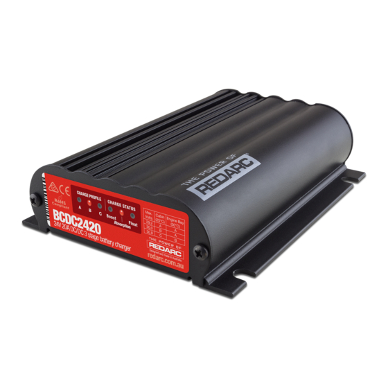
Summary of Contents for Redarc BCDC2420
- Page 1 In-vehicle 3-Stage 24V Battery Charger BCDC2420 & BCDC2420-LV...
- Page 2 Do NOT alter or disassemble the Battery Charger under any circumstances. All faulty units must be returned to REDARC for repair. Incorrect handling or reassembly may result in a risk of electric shock or fi re and may void the unit warranty.
-
Page 3: Table Of Contents
Cable Sizing Wiring Fusing 3 Troubleshooting 4 Frequently Asked Questions 5 Two Year Warranty Specifi cations Part Number BCDC2420(-LV) Continuous Current Rating Input Fuse Rating 12V/24V 60A/40A (Not supplied) Output Fuse Rating 30A (Not supplied) Output Power 600W DC Input Voltage Range... -
Page 4: Product Function
PRODUCT FUNCTION The BCDC2420(-LV) is a three-stage, 24V DC-DC battery charger that operates from an alternator input of 12V nominal or a 12V nominal solar panel input. The BCDC2420 will also charge from an alternator input from a 24V nominal vehicle* . -
Page 5: Charging Algorithm
PRODUCT FUNCTION Charging Algorithm When the BCDC2420(-LV) is turned on, it will move into the Boost stage. The Boost stage maintains a constant current until the battery voltage reaches the Absorption Voltage. The current during Boost stage may vary throughout operation in order to maintain a safe operating temperature, or to limit the difference between input and output voltages. -
Page 6: Error Codes
NOTE: Appropriate connections must be made to the wires with a continuous current rating of at least 20A for the BCDC2420(-LV). Failure to do so may cause damage to the unit and vehicle. -
Page 7: Blue Wire - Source Select
BCDC2420-LV. Input Source Positive 2.1.2 Solar Input The BCDC2420 is also capable of charging the auxiliary Connected battery from a Solar source. The unit will accept an Blue Wire input directly from an unregulated 12V nominal solar panels and act as a MPPT Solar Regulator. To select the Solar charging mode, the BLUE ‘Source Select’... - Page 8 INSTALLATION ORANGE wire - Battery Type Select The ORANGE wire is used to select the Maximum output voltage. This is achieved by connecting in the following way: Connected To select Profi le A leave the ORANGE wire Orange Wire disconnected. This will set the Maximum voltage to 29.2V.
-
Page 9: Brown Wire - Auxiliary Battery Positive
INSTALLATION BROWN wire - Auxiliary Battery Positive The BROWN wire should be connected to Brown Wire the auxiliary battery’s positive terminal. This should be a maximum of 1 metre in cable length from the battery. Appropriate size fuses should be used as per the specifi cations table Auxiliary on page 2. -
Page 10: Cable Sizing
20.28 Wiring The heavy gauge wires on the BCDC2420(-LV) unit carry peak currents of up to 40 Amps, and it is important to make a good, low resistance, electrical connection that will not degrade over time. Failure to make a good, reliable contact may result in breakdown of the wire insulation and cause a short circuit, or worst case a fi... - Page 11 Start All ground points must Battery Battery be connected to chassis earth. *Fuse Ratings as per table on Page 2 Figure 2.8a - BCDC2420 Standard setup for a 12V or 24V Start Battery BCDC2420-LV Optional LED INPUT Green Loads Load...
-
Page 12: Wiring
A Relay suitable for 12V Vehicle installations is earth. available as part of the REDARC RK1260 Relay Kit. The kit also includes butt-splice connectors, a *Fuse Ratings as per table on Page 2 wiring loom, heat shrink, and instructions. -
Page 13: Fusing
INSTALLATION Fusing A single fuse and holder REDARC recommend using MIDI style bolt down fuses as they setup from the Fuse Kits ensure a low resistance connection. The REDARC FK40 and FK60 available from REDARC. Part number FK40 (40A) fuse kits are recommended. -
Page 14: Frequently Asked Questions
The BCDC2420(-LV) will turn OFF for a split second every 100 seconds to measure the unloaded voltage at the battery. When the BCDC2420(-LV) turns off it is not drawing any load from the start battery, no load means that there is no voltage drop over the cable run. This allows the BCDC2420(- LV) to measure the actual battery voltage, or the voltage at the battery. -
Page 15: Years
Friendly, personalised, professional service and product support In the unlikely event that a technical issue arises with a Redarc product, customers are encouraged to initially contact the Redarc Technical Support Team on (08) 8322 4848 In the unlikely event that a technical issue arises with a Redarc product, customers are encouraged to initially contact the Redarc Technical Support Team on (08) 8322 4848 or or power@redarc.com.au... -
Page 16: Warranty
For specific USA Warranty terms please visit: www.redarcelectronics.com Free technical assistance! please contact REDARC Electronics 23 Brodie Road North, Lonsdale SA (08) 8322 4848 power@redarc.com.au www.redarc.com.au Copyright © 2018 REDARC Electronics Pty Ltd. All rights reserved. WARBCDC2420 - REV4 www.redarc.com.au...


Need help?
Do you have a question about the BCDC2420 and is the answer not in the manual?
Questions and answers