Advertisement
Advertisement

Related Manuals for Redarc BCDC1220


Summary of Contents for Redarc BCDC1220
- Page 1 20A In-vehicle 3-Stage 12V Battery Charger BCDC1220...
-
Page 2: Warnings And Safety Instructions
Attempting to service the unit yourself may result in electric shock or fi re and will void the unit warranty. Do NOT use the BCDC1220 to charge non-rechargeable batteries. Doing so may result in harm to the user and/or damage to the BCDC1220. Only use the BCDC1220 for charging Standard Lead Acid, Calcium content, Gel &... -
Page 3: Table Of Contents
Specifi cations 1 Product Function 1. Operation 2. Turn On/Off Thresholds 3. Display Panel 2 Installation 1. Wiring 3 Two Year Warranty Specifi cations BCDC1220 DC Input Voltage Range 9V-32V Gel/AGM Std Lead Acid Calcium Content Absorption Voltage 14.5V 14.9V 15.3V... -
Page 4: Product Function
The BCDC1220 is a multi stage, 12V, 20A, DC-DC battery charger that operates from an input of either 12V or 24V nominal. The input voltage of the BCDC1220 can be above, below or equal to the output voltage making it ideal for charging from a 24V vehicle or charging an auxiliary 12V battery where the distance from the main battery may cause a signifi... -
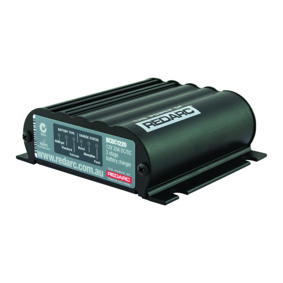
Page 5: Display Panel
PRODUCT FUNCTION Display Panel The BCDC1220 has three Battery Type Settings available. These settings enable optimal charging profi les for the auxiliary battery. The battery type selected is displayed via the LEDs on the front panel in the section ‘Battery Type’. In addition to the battery type, the status of the charger is indicated via three LEDs. - Page 6 INSTALLATION 1. Wire the ‘Common Ground’ wire to a ground point that is common to both the Start battery and the Auxiliary battery to be charged. This point may be on the chassis of the vehicle, on the chassis of the trailer/camper/caravan or directly wired to both batteries, depending on your installation requirements.
-
Page 7: Wiring
Calcium) may need to be selected to avoid damage to the battery. Wiring The wires on the BCDC1220 unit carry higher than 20 Amp, and it is important to make a good, low resistance, electrical connection that will not degrade over time. - Page 8 INSTALLATION Crimp here. Slip heatshrink over wire and insert wires into Crimp both wires to the butt splice using indent butt splice. Keep heatshrink away from joint until type crimpers. after soldering is complete and has cooled. Solder here. Solder the wires to the butt splice. Ensure that a Wait for the butt splice to cool, slip heatshrink good connection is made.
- Page 9 INSTALLATION INPUT Load Loads Fuse Fuse Fuse Battery config wire To vehicle ignition Note: Power wires must be All ground points must Auxiliary Start at least 3mm² and must be be connected to chassis Battery Battery crimped using an earth. appropriate crimp tool.
- Page 11 Friendly, personalised, professional service and product support In the unlikely event that a technical issue arises with a Redarc product, customers are encouraged to initially contact the Redarc Technical Support Team on (08) 8322 4848 In the unlikely event that a technical issue arises with a Redarc product, customers are encouraged to initially contact the Redarc Technical Support Team on (08) 8322 4848 or or power@redarc.com.au...
- Page 12 Free technical assistance! please contact Redarc Electronics 23 Brodie Road North, Lonsdale SA (08) 8322 4848 power@redarc.com.au www.redarc.com.au Copyright © 2012 Redarc Electronics Pty Ltd. All rights reserved. WARBCDC1220 - REV3 www.redarc.com.au...
Need help?
Do you have a question about the BCDC1220 and is the answer not in the manual?
Questions and answers
what setting for lithium battery