H3C S5800-32F Installation Manual
S5800 series ethernet switches
Hide thumbs
Also See for H3C S5800-32F:
- Installation manual (101 pages) ,
- Instruction manual (30 pages)

Related Manuals for H3C H3C S5800-32F


Summary of Contents for H3C H3C S5800-32F
- Page 1 H3C S5800 Series Ethernet Switches Installation Manual Hangzhou H3C Technologies Co., Ltd. Manual Version: 5W101-20090604...
- Page 2 Copyright © 2009, Hangzhou H3C Technologies Co., Ltd. and its licensors H3C Technologies Co., Ltd., a subsidiary of 3Com Corporation. All Rights Reserved No part of this manual may be reproduced or transmitted in any form or by any means without prior written consent of Hangzhou H3C Technologies Co., Ltd.
-
Page 3: About This Manual
About This Manual Organization H3C S5800 Series Ethernet Switches Installation Manual is organized as follows: Chapter Contents Briefly introduces the appearance, system description, as well as the 1 Product Overview features and applications of the H3C S5800 series switches. Describes requirements installation site,... - Page 4 Related Documentation Manual Description H3C PSR150-A & PSR150-D Power Introduces the features, specifications, installation and Modules User Manual removal of the PSR150-A and PSR150-D power modules. Introduces the features, specifications, installation and H3C PSR300-12A & PSR300-12D1 removal of the PSR300-12A and PSR300-12D1 power Power Modules User Manual modules.
- Page 5 Documentation Feedback You can e-mail your comments about product documentation to info@h3c.com. We appreciate your comments. Environmental Protection This product has been designed to comply with the requirements on environmental protection. For the proper storage, use and disposal of this product, national laws and regulations must be observed.
-
Page 6: Table Of Contents
Table of Contents 1 Product Overview ······································································································································1-1 Overview ·················································································································································1-1 S5800-60C-PWR ····································································································································1-4 Front Panel ······································································································································1-4 Rear Panel·······································································································································1-5 S5800-56C ··············································································································································1-6 Front Panel ······································································································································1-6 Rear Panel·······································································································································1-7 S5800-56C-PWR ····································································································································1-8 Front Panel ······································································································································1-8 Rear Panel·······································································································································1-8 S5800-32C ··············································································································································1-9 Front Panel ······································································································································1-9 Rear Panel·······································································································································1-9 S5800-32C-PWR ··································································································································1-10 Front Panel ····································································································································1-10 Rear Panel·····································································································································1-10 S5800-32F ············································································································································1-11 Front Panel ····································································································································1-11... - Page 7 OAP Card··············································································································································1-27 Hot Swappable PoE Module ·················································································································1-27 2 Installation Preparations···························································································································2-1 Safety Precautions ··································································································································2-1 Installation Site········································································································································2-1 Temperature/Humidity ·····················································································································2-1 Cleanness········································································································································2-2 Electromagnetic Susceptibility·········································································································2-2 Laser Safety ····································································································································2-2 Installation Tools ·····································································································································2-3 3 Installing a Switch ·····································································································································3-1 Installation Flow of the Switch·················································································································3-2 Installing the Switch into a 19-Inch Rack Using Mounting Brackets·······················································3-2 Introduction to Mounting Brackets and Cable Management Brackets ············································3-3 Attaching the Mounting Brackets to a Switch ··················································································3-4 Mounting the Switch to a Rack········································································································3-6...
- Page 8 Checking Before Power-On·············································································································4-5 Powering On the Switch ··················································································································4-5 Changing the Boot Mode·················································································································4-7 5 Loading Software·······································································································································5-1 Introduction ·············································································································································5-1 Approaches for Loading Software···········································································································5-1 Loading Software Through the Boot ROM Menu····················································································5-2 Introduction to the Boot ROM Menu································································································5-2 Loading Software Using XMODEM Through Console Port·····························································5-4 Loading Software Using TFTP Through Ethernet Port ·································································5-11 Loading Software Using FTP Through Ethernet Port····································································5-15 Loading Software Through CLI ·············································································································5-18...
-
Page 9: Product Overview
Product Overview Overview H3C S5800 Series Ethernet Switches (hereinafter referred to as the S5800 series) are Layer 3 Gigabit Ethernet switching products developed by Hangzhou H3C Technologies Co., Ltd. (hereinafter referred to as H3C). The S5800 series provide abundant service features. They provide the IPv6 forwarding function and 10 GE uplink interfaces. - Page 10 S5800-60C- S5800-56C- S5800-32 S5800-3 Item S5800-56C S5800-32C C-PWR The console port of the S5800-60C-PWR, S5800-32C or S5800-32C-PWR is Console available on the front panel. port The console port of the S5800-56C, S5800-56C-PWR or S5800-32F is available under the logo panel on the front panel. Manageme 1, on the nt Ethernet...
- Page 11 S5800-60C- S5800-56C- S5800-32 S5800-3 Item S5800-56C S5800-32C C-PWR PSR300-12A Supported PSR150 PSR300-12D swappable — — — — PSR150 power PSR750-A modules PSR750-D RPS power RPS1000-A RPS1000- RPS800 module RPS1000-A3 RPS800-A RPS800-A supported Rated voltage: 100 VAC to 240 VAC, 50/60 Hz Max voltage: 90 VAC to 264 VAC, 47/63 Hz Rated voltage:...
-
Page 12: S5800-60C-Pwr
S5800-60C- S5800-56C- S5800-32 S5800-3 Item S5800-56C S5800-32C C-PWR Operating humidity 10% to 90% (nonconden sing) S5800-60C-PWR Front Panel Figure 1-1 S5800-60C-PWR front panel (1) Interface card 1 (2) Interface card 2 (3) 10/100/1000Base-T auto-sensing Ethernet (4) Seven-segment LED port status LED (5) Port mode LED (6) Console port (7) USB interface... -
Page 13: Rear Panel
Rear Panel Figure 1-2 S5800-60C-PWR rear panel (1) OAP card filler panel (2) PoE module (3) Grounding screw (4) Filler modules (5) Hot swappable power module 1 (6) Hot swappable power module 2 (7) Hot swappable fan tray The S5800-60C-PWR provides two power module slots on its rear panel. Hot swappable power module slot 1 is empty when the switch is shipped, and hot swappable power module 2 is installed with a filler panel. -
Page 14: S5800-56C
S5800-56C Front Panel Figure 1-3 S5800-56C front panel (1) 10/100/1000Base-T auto-sensing Ethernet (2) 10/100/1000Base-T auto-sensing Ethernet port port status LED (3) Seven-segment LED (4) Port mode LED (6) Logo panel (A console port and a USB interface (5) SFP+ interface status LED are under this logo panel) (7) System status LED (SYS) (8) RPS status LED (RPS) -
Page 15: Rear Panel
Figure 1-5 S5800-56C logo panel II (1) Tab of the logo panel (2) Pin of the logo panel (3) Console port (4) USB interface (5) Slot on the front panel (6) Rubber strip Rear Panel Figure 1-6 S5800-56C rear panel (1) Bail latch (2) RPS receptacle protective cover (3) Grounding screw... -
Page 16: S5800-56C-Pwr
S5800-56C-PWR Front Panel Figure 1-7 S5800-56C-PWR front panel (1) 10/100/1000Base-T auto-sensing Ethernet (2) 10/100/1000Base-T auto-sensing Ethernet port port status LED (3) Seven-segment LED (4) Port mode LED (6) Logo panel (A console port and a USB (5) SFP+ interface status LED interface are under this logo panel) (7) System status LED (SYS) (8) RPS status LED (RPS) -
Page 17: S5800-32C
S5800-32C Front Panel Figure 1-9 S5800-32C front panel (1) 10/100/1000Base-T auto-sensing Ethernet (2) 10/100/1000Base-T auto-sensing Ethernet port port status LED (3) SFP+ interface status LED (4) Console port (5) USB interface (6) Seven-segment LED (7) Port mode LED (8) System status LED (SYS) (9) RPS status LED (RPS) (10) Interface card status LED (SLOT1) (11) Port status LED mode switching button... -
Page 18: S5800-32C-Pwr
S5800-32C-PWR Front Panel Figure 1-11 S5800-32C-PWR front panel (1) 10/100/1000Base-T auto-sensing Ethernet (2) 10/100/1000Base-T auto-sensing Ethernet port port status LED (3) SFP+ interface status LED (4) Console port (5) USB interface (6) Seven-segment LED (7) Port mode LED (8) System status LED (SYS) (9) RPS status LED (RPS) (10) Interface card status LED (SLOT1) (11) Port status LED mode switching button... -
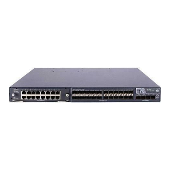
Page 19: S5800-32F
S5800-32F Front Panel Figure 1-13 S5800-32F front panel (1) Interface card 1 (2) 100/1000Base-X SFP interface (3) 10/100/1000Base-X SFP interface status (4) Seven-segment LED (5) Port mode LED (6) SFP+ interface status LED (7) Logo panel (A console port and a USB (8) System status LED (SYS) interface are under this logo panel) (9) Hot swappable power module 1 status LED... -
Page 20: Rear Panel
Rear Panel Figure 1-14 S5800-32F rear panel (1) Hot swappable power module 1 (2) Hot swappable power module 2 (3) Hot swappable fan tray (4) Management Ethernet port (5) Grounding screw (6) Management Ethernet port ACT status LED (7) Management Ethernet port LINK status LED The S5800-32F provides two power module slots on its rear panel. -
Page 21: Management Ethernet Port
Management Ethernet Port The S5800-32F provides a management Ethernet port on its rear panel. The port connects to a computer to perform system program loading and debugging without being affected by the switching chip working status; or connects to a remote network management station (NMS) to implement remote management of the system. - Page 22 Table 1-5 Transceivers supported by the S5800 series 10/100/1000Base-X SFP interfaces Transceiver Central Connect transmis Transceiver Fiber type wavelength sion distance 50/125 µm 550 m multimode (1804.5 optical fiber SFP-GE-SX-MM850-A 850 nm 62.5/125 µm 275 m multimode (902.2 ft) optical fiber 10 km (about SFP-GE-LX-SM1310-A...
-
Page 23: Sfp+ Interface
You are recommended to use SFP transceivers of H3C on the S5800 series. The types of SFP transceivers may update with time. For information about transceivers, contact H3C technical support or marketing staff. For the models and specifications of each kind of transceivers, refer to H3C Low End Series Ethernet Switches Pluggable Modules Manual. - Page 24 Transceive Central Connect transmis r/Cable Transceiver/Cable Fiber wavelength sion type distance 50/125 µm 300 m SFP-XG-SX-MM850-A 850 nm multimode optical (984.3 ft.) fiber 62.5/125 µm 10 GE SFP+ SFP-XG-LX220-MM13 220 m multimode optical transceiver (721.8 ft.) fiber 1310 nm 9/125 µm single 10 km SFP-XG-LX-SM1310 mode optical...
-
Page 25: Leds
LEDs Table 1-7 LEDs Device support Description System Status LED System status LED All series page 1-17. Hot Swappable Power Hot swappable power Module Status LEDs on page S5800-60C-PWR and S5800-32F module LED 1-18. All series (except S5800-60C-PWR RPS Status LED on page RPS status LED and S5800-32F) -
Page 26: Hot Swappable Power Module Status Leds
Hot Swappable Power Module Status LEDs The hot swappable power module status LEDs help you determine the working status of a hot swappable power module. Refer to Table 1-9 for details. Table 1-9 Description of the hot swappable power module LEDs Status Description Hot swappable power module slot 1 is installed with a power... -
Page 27: Port Mode Led
Port Mode LED The port mode LED on the S5800 series can display the working status of a port for you to obtain more device information. You can use the port mode switching button to change the status of the port mode LED. -
Page 28: 10/100/1000Base-T Auto-Sensing Ethernet Port Status Led
Status System Description status Seven-segment LED (SYS) The LED displays c. The current switch is a candidate switch in the cluster. The LED displays the specific numbers. The member ID of the current switch (A stands for 10). The seven-segment LED, the system status LED, and the port mode LED on the S5800-60C-PWR, S5800-56C-PWR or S5800-32C-PWR that supports PoE can display the PoE power consumption percentage of the switch. -
Page 29: 100/1000Base-X Sfp Interface Status Led
Status Description Port mode Ethernet port status Steady green PoE power supply is normal. Power consumption of the device connected to the port Flashing green exceeds the upper limit of the power supply Flashing green (3 Hz) (1 Hz) (PoE consumption of the port, or the available power of the mode, switch is not enough for power supply of the port. -
Page 30: Sfp+ Interface Status Led
SFP+ Interface Status LED The port mode LED and the SFP+ interface status LED together indicate the SFP+ interface operation status. For details, refer to Table 1-17. Table 1-17 SFP+ interface status LEDs description Status Description Port mode SFP+ interface status LED The port operates at a rate of 10 Gbps;... -
Page 31: Poe Module Status Led
Table 1-19 OAP card status LED description Mark Status Description Green The OAP card is in the slot and operates normally. The inserted OAP card type is incorrect or the OAP card SLOT3 Flashing yellow (1 Hz) fails. No OAP card is installed. PoE Module Status LED The S5800-60C-PWR provides a PoE module status LED (SLOT4) on its front panel. - Page 32 Table 1-22 Hot swappable power module models and specifications Model Item Specifications Device model 100 VAC to 240 VAC; Rated voltage range 50 Hz or 60 Hz 90 VAC to 264 VAC; 47 Max voltage range Hz or 63 Hz PSR150-A S5800-32F Output voltage...
-
Page 33: Hot Swappable Fan Trays
Model Item Specifications Device model Rated voltage range –48 VDC to –60 VDC Max voltage range –40.5 VDC to –72 VDC Dual outputs, 12 V and Output voltage –52 V respectively PSR750-D S5800-60C-PWR 25 A for 12 V output voltage Max output current 32 A for –52 V output voltage... -
Page 34: Interface Cards
Table 1-23 Fan tray specifications Model Specification Description Two 70 × 70 × 25.4 mm (2.76 × 2.76 × 1 in.) fans Fan number Four 40 × 40 × 28 mm (1.57 × 1.57 × 1.1 in.) fans 70 × 70 × 25.4 mm (2.76 × 2.76 × 1 in.) fans: 4700 R.P.M Fan speed 40 ×... -
Page 35: Oap Card
OAP Card The S5800-60C-PWR provides one OAP card slot on its rear panel, and a filler panel is installed on the slot when the switch is shipped. You can purchase OAP cards for wireless and security services. For the introduction to OAP cards, see Table 1-25. -
Page 36: Installation Preparations
Installation Preparations Safety Precautions To avoid any device impairment and bodily injury caused by improper use, observe these rules: Before cleaning the switch, plug out the power cord of the power module of the switch first. Do not clean the switch with wet cloth or liquid. Do not place the switch near water or in a damp environment. -
Page 37: Cleanness
Cleanness Dust is a hazard to the operating safety of your device. The dust accumulated on the chassis can be adsorbed by static electricity and result in poor contact of metal connectors or metal contact points. Especially when the indoor relative humidity is low, electrostatic adsorption is more likely to happen. This can not only shorten the service life of your device but also cause communications failures. -
Page 38: Installation Tools
When an optional interface module or SFP/SFP+ module on the S5800 series is operating, do not stare into the optical port because the laser light emitted from the optical fiber may hurt your eyes. Installation Tools Flat-blade screwdriver Phillips screwdriver ESD-preventive wrist strap The installation tools are not shipped with the S5800 series. -
Page 39: Installing A Switch
Installing a Switch On a mounting screw of the chassis of the H3C series switches, there is a seal labeled with H3C. You need to keep it intact before asking the agent to maintain the switch. You need to get the permission of the local agent before you can open the chassis. -
Page 40: Installation Flow Of The Switch
Installation Flow of the Switch Figure 3-1 Hardware installation flow of the switch Installing the Switch into a 19-Inch Rack Using Mounting Brackets The S5800 series can be installed into a 19-inch rack with load-bearing mounting brackets. Figure 3-2 Figure 3-3 show how to install an S5800 series into a 19-inch rack. -
Page 41: Introduction To Mounting Brackets And Cable Management Brackets
Figure 3-2 Install an S5800-60C-PWR switch into a 19-inch rack Front or rear Mount the cable management Mount the mounting bracket and mounting bracket switch to a kit to the switch's two sides rack Choose proper installation positions for mounting brackets (Front, center, or rear mounting) Install the mounting Mount the... -
Page 42: Attaching The Mounting Brackets To A Switch
The S5800-60C-PWR also provides a pair of cable management brackets for organizing and routing cables. The cable management brackets are fixed to the mounting brackets before they are shipped, as shown in Figure 3-5. Figure 3-5 2U cable management bracket and mounting bracket kit (1) Cable management bracket (2) Mounting bracket Attaching the Mounting Brackets to a Switch... - Page 43 Figure 3-7 Attach the 1U mounting bracket for center mounting Figure 3-8 Attach the 1U mounting bracket for rear mounting Note that each of the above figures shows only how to install one 1U bracket, because the installation procedures of the two brackets are the same. Figure 3-9 Attach the 2U cable management bracket and mounting bracket kits Note that if the 2U mounting bracket is used for a center mounting of the S5800-60C-PWR, you need to separate the mounting bracket and cable management bracket (they are fixed by default;...
-
Page 44: Mounting The Switch To A Rack
Figure 3-10 Separate the cable management bracket and mounting bracket (1) Captive screws (2) Cable management bracket (3) Mounting bracket Mounting the Switch to a Rack Step1 Wear an ESD-preventive wrist strap and make sure the rack is well grounded and is firm enough to hold the switch and cables. -
Page 45: Mounting The Switch On A Workbench
Figure 3-11 Mount the 1U S5800 series to a rack The procedures of installing an S5800-60C-PWR (2U) and other S5800 series (1U) into a rack are similar. For how to mount a switch to a rack based on different positions of the mounting brackets, see Figure 3-11. -
Page 46: Connecting The Ground Wire
Step1 Place the switch with bottom up carefully, and then clean the round holes on the chassis bottom with dry cloth. Step2 Attach the rubber feet to the four round holes on the chassis bottom. Step3 Place the switch with upside up on the workbench. During the operation, you simply need to: Make sure that the workbench is flat and sturdy. - Page 47 Figure 3-12 Connect the PGND cable to the grounding hole of switch (1) Rear panel of the switch (2) Grounding sign (3) Grounding hole (4) OT terminal (5) PGND cable (6) Grounding screw To attach the other end of the PGND cable to the grounding strip in the equipment room, follow these steps: Step1 Cut the PGND cable to a proper length according to the distance between the switch and the grounding strip.
-
Page 48: Where A Grounding Conductor Can Be Buried
The fire main and lightning rod of a building are not suitable for grounding the switch. The ground wire of the switch should be connected to the grounding device for the equipment room. Where a Grounding Conductor Can be Buried When there is no grounding strip, but an area with exposed earth is available nearby where a grounding conductor can be buried, hammer a 0.5 m (1.64 ft.) or longer angle iron or steel tube into the earth. - Page 49 Figure 3-15 Ground through an AC power PE wire (1) Three-wire AC power input cable (2) Switch rear panel When the Switch is DC-powered For a DC-powered switch, if neither of the first two conditions mentioned above is available, ground the switch through the return wire (RTN) of the DC power supply.
-
Page 50: Installing A Power Module
Use the PGND cable provided with the switch to connect the grounding strip in the equipment room. Otherwise, the grounding effect may not be ensured, which easily causes damage to the switch. Installing a Power Module The S5800-60C-PWR/S5800-32F provides two power module slots on its rear panel. Hot swappable power module slot 1 is empty when the switch is shipped, and hot swappable power module 2 is installed with a filler panel. - Page 51 Figure 3-19 Install the PSR750-A/PSR750-D to the switch (remove the blank filler module) Figure 3-20 Install the PSR750-A to the switch ② ① Figure 3-21 Install other power module models to the switch 3-13...
-
Page 52: Removing The Power Module
If a power module slot has a filler panel, remove the filler panel before inserting a power module. To prevent damage to the power module or the connector on the backplane of the powered device, insert the power module gently. If you encounter a hard resistance while inserting the power module, pull out the power module and then insert it again. -
Page 53: Connecting An Ac Power Cord
Power module Power supply mode Connection method Connecting a power cord to PSR150-A AC power supply the PSR150-A Connecting a power cord to –48 VDC the PSR150-D (–48 VDC equipment-room equipment-room power power supply DC power supply) PSR150-D supply Connecting a power cord to –54 VDC RPS the PSR150-D (–54 VDC RPS power supply... -
Page 54: Connecting An Rps Dc Power Cord
Figure 3-23 Connect an AC power cord to the S5800-56C-PWR/S5800-32C-PWR II Figure 3-24 Connect an AC power cord to the S5800-56C/S5800-32C I Figure 3-25 Connect an AC power cord to the S5800-56C/S5800-32C II Connecting an RPS DC Power Cord Connecting a –54 VDC RPS power cord The S5800-56C-PWR and S5800-32C-PWR support –54 VDC RPS power supply. - Page 55 Figure 3-26 Connect an RPS DC power cord to the S5800-56C-PWR/S5800-32C-PWR Connecting a 12 VDC RPS power cord The S5800-56C and S5800-32C support 12 VDC RPS power supply. Follow these steps to connect the power cord: Step1 Loosen the captive screws on the RPS receptacle protective cover and remove the protective cover, as shown in Figure 3-27.
-
Page 56: Connecting A Power Cord To The Psr150-A/Psr150
Connecting a Power Cord to the PSR150-A/PSR150-D Connecting a power cord to the PSR150-A Step1 Pull the bail latch leftwards (see Figure 3-29). Step2 Connect one end of the AC power cord to the AC receptacle on the power module (see callout 1 in Figure 3-30). -
Page 57: Connecting A Power Cord To The Psr300-12A/Psr300-12D1
Figure 3-31 Connect a DC power cord Pay attention to the positive (+) and negative (-) marks on the power cord to avoid connection mistakes. Connecting a power cord to the PSR150-D (–54 VDC RPS power supply) The PSR150-D supports –54 VDC RPS power supply. Follow these steps to connect the power cord: Step1 Keep the upside of the –54 VDC RPS plug on top and plug it in the RPS DC receptacle (see callout 1 in Figure 3-31). - Page 58 Figure 3-32 Connect an AC power cord I Figure 3-33 Connect an AC power cord II Connecting a power cord to the PSR300-12D1 (–48 VDC equipment-room power supply) Step1 Switch off the DC power module. Step2 Keep the upside of the DC plug shipped with the device on top and plug it in the DC receptacle (see callout 1 in Figure 3-34).
-
Page 59: Connecting A Power Cord To The Psr750-A&Psr750
Figure 3-34 Connect a DC power cord Pay attention to the positive (+) and negative (-) marks on the power cord to avoid connection mistakes. Connecting a power cord to the PSR300-12D1 (–54 VDC RPS power supply) The PSR300-12D1 supports –54 VDC RPS power supply. Follow these steps to connect the power cord: Step1 Keep the upside of the –54 VDC RPS plug on top and plug it in the RPS DC receptacle (see callout 1 in Figure... - Page 60 Figure 3-35 Connect an AC power cord I Figure 3-36 Connect an AC power cord II Connecting a power cord to the PSR750-D (–54 VDC RPS power supply) To ensure normal PoE power supply to the S5800-60C-PWR using the PSR750-D, you need to select the RPS1000-A3 of H3C that provides a voltage range from –52V to –55V.
- Page 61 To ensure normal power supply to S5800-60C-PWR using the RPS1000-A3, pay attention to the following: The RPS1000-A3 has two power module slots. Make sure that both slots are inserted with a power module. If only one power module is used, it may enter the protection state due to over current and then stop providing power supply to the switch.
-
Page 62: Installing An Interface Card
Installing an Interface Card The S5800 series provides fixed ports as well as expansion slots for optional interface cards. Filler panels are installed on the expansion card slots. For details about optional interface cards, refer to Interface Cards on page 1-26. The installation and removal of various interface cards are similar. -
Page 63: Removing An Interface Card
Figure 3-40 Install an interface card (1) Switch's front panel (2) Interface card (3) Push-in direction (4) Inward direction Step4 Tighten the captive screws with a Phillips screwdriver to fix the interface card. Removing an Interface Card Step1 Wear an ESD-preventive wrist strap, ensure a good skin contact and make sure that the ESD-preventive wrist strap is properly grounded. -
Page 64: Installing An Oap Card
Installing an OAP Card Installing an OAP Card to the Switch Step1 Wear an ESD-preventive wrist strap, ensure a good skin contact and make sure that the ESD-preventive wrist strap is properly grounded. Step2 Loosen the captive screws on the filler panel with a Phillips screwdriver, as shown in Figure 3-42, and remove the filler panel from the slot to be used. -
Page 65: Removing An Oap Card
When installing the OAP card, note the following: Make sure that the ejector levers are on the top of the OAP card. Then insert and push the OAP card in the slot along the guide rails. Do not touch the surface-mounted components directly with your hands. Do not use excessive force while installing the OAP card. -
Page 66: Installing A Poe Module
When removing the OAP card, note the following: Do not touch the surface-mounted components directly with your hands. Do not use excessive force while removing the OAP card. If you do not install a new OAP card in the slot, install a filler panel to prevent dust from entering the switch and ensure normal ventilation in the switch. -
Page 67: Verifying The Installation
Step2 Loosen the captive screws on the PoE module counterclockwise with the Philips screwdriver until all spring pressure is released. Step3 Hold each ejector lever with a hand and pull the ejector levers outward (see callout 1 in Figure 3-46). Then pull out the PoE module slowly along the guide rails (see callout 2 in Figure 3-46). -
Page 68: Initial Power-On
Initial Power-On Setting Up the Configuration Environment Set up the configuration environment as follows: Connect a terminal (a PC in this example) to the console port on the switch with a console cable. Figure 4-1 Network diagram for configuration environment setup Connecting the Console Cable Console Cable A console cable is an 8-core shielded cable. -
Page 69: Connection Procedure
RJ-45 Signal Direction DB-9 ← → → → → Connection Procedure When you want to use the terminal to configure the switch, follow these steps to connect a terminal device to the switch using the console cable: Plug the DB-9 female connector of the console cable to the serial port of the console terminal or Connect the RJ-45 connector of the console cable to the console port of the switch. - Page 70 Data bits: 8 Parity: None Stop bits: 1 Flow control: None Emulation: VT100 The specific procedure is as follows: Step1 Select Start > Programs > Accessories > Communications > HyperTerminal to enter the HyperTerminal window. The Connection Description dialog box appears, as shown below. Figure 4-3 Connection description of the HyperTerminal Step2 Type the name of the new connection in the Name text box and click OK.
- Page 71 Step3 Click OK after selecting a serial port. The following dialog box appears. Set Bits per second to 9600, Data bits to 8, Parity to None, Stop bits to 1, and Flow control to None. Figure 4-5 Set the serial port parameters Step4 Click OK after setting the serial port parameters and the system enters the HyperTerminal window shown below.
-
Page 72: Booting The Switch
Step5 Click Properties in the HyperTerminal window to enter the Switch Properties dialog box. Click the Settings tab, set the emulation to VT100, and then click OK. Figure 4-7 Set terminal emulation in Switch Properties dialog box Booting the Switch Checking Before Power-On Before powering on the switch, verify that: The power cable is properly connected. - Page 73 Memory Size : 512MB Flash Size : 512MB CPLD Version : 001 PCB Version : Ver.B Mac Address : 000ef2005800 Press Ctrl-B to enter Extended Boot menu...4 The last line asks whether you want to enter the Boot ROM menu. The system waits five seconds for your response.
-
Page 74: Changing The Boot Mode
Item Description Skip the current configuration file (this configuration is valid 7. Skip current configuration file once) 8. Set BootRom password recovery Restore the Boot ROM password 9. Set switch startup mode Set the startup mode of the switch 0. Reboot Restart the switch If you perform no operation or press a key other than Ctrl + B within one second, once the remaining waiting time becomes zero, the system begins to automatically start up and the following... - Page 75 3. Display all files in flash 4. Delete file from flash 5. Modify BootRom password 6. Enter BootRom upgrade menu 7. Skip current configuration file 8. Set BootRom password recovery 9. Set switch startup mode 0. Reboot Enter your choice(0-9): Enter 9.
- Page 76 Press Ctrl-B to enter Extended Boot menu...1 In normal startup mode, the waiting time here is one second. If you press Ctrl + B within five seconds, the Boot ROM menu is displayed. If you perform no operation or press a key other than Ctrl + B within five seconds, the system begins to automatically start up and the following information is displayed: Starting to get the main application file--flash:/S5800_release.bin....
-
Page 77: Loading Software
Loading Software Introduction Loading software on the switch involves loading application files and upgrading the Boot ROM program by using the host software package. The host software package of the S5800 series comprises the Boot ROM files and application files with the file name extension .bin. Loading application files: Download the host software package to the flash memory on the switch and set the attribute (main, backup, or none) of the application files. -
Page 78: Loading Software Through The Boot Rom Menu
Each S5800-32F series switch provides a management Ethernet port, which can operate regardless of the working status of the switching chip. To upgrade the Boot ROM program or load application files when the switching chip fails to operate normally, you are recommended to use the management Ethernet port. - Page 79 By default, the system starts up in normal mode and the waiting time here is five seconds. If you set the startup mode to fast, the waiting time is one second. For the setting of the startup mode, refer to Changing the Boot Mode on page 4-7.
-
Page 80: Loading Software Using Xmodem Through Console Port
Currently, Boot ROM files are not provided separately by the S5800 series; instead, they are stored together with the application files with name extension .bin in the host software package. The procedures for upgrading the Boot ROM program and loading application files are similar except that you need to select different items (1 for loading application files, and 6 for loading Boot ROM files) in the Boot ROM menu. - Page 81 Task Remarks Required Update the Boot ROM file on the switch Update the Boot ROM file on the switch. Optional Set the baud rate of the serial port on the terminal Restore the download rate to the default to be consistent with the default rate of the console port on the switch.
- Page 82 0. Return to boot menu Enter your choice(0-3): The items in the protocol parameter setting menu are described in Table 5-4. Table 5-4 Description of the protocol parameter setting menu Item Description 1. Set TFTP protocol parameter Set TFTP parameters 2.
- Page 83 Step1 Select Call > Disconnect in the HyperTerminal window to disconnect the terminal from the switch. Figure 5-1 Disconnect the terminal from the switch Step2 Select File > Properties. In the Properties dialog box, click Configure (as shown in Figure 5-2), and then select 115200 from the Bits per second drop-down list box (as shown in Figure...
- Page 84 Figure 5-3 Modify the baud rate Step3 Select Call > Call to reestablish the connection. Figure 5-4 Reestablish the connection The new settings can take effect only after you reestablish the connection. Upload an application file from the terminal to the switch Step1 After establishing a connection between the terminal and the switch, press Enter in the HyperTerminal window to enter the system file downloading state.
- Page 85 Press Ctrl + X to quit downloading files; otherwise, proceed as follows. Step2 Select Transfer > Send File in the HyperTerminal window (as shown in Figure 5-5). Click Browse in the pop-up dialog box (as shown in Figure 5-6) to select the application file to be downloaded (for example, update.bin), and select Xmodem from the Protocol drop-down list.
- Page 86 Figure 5-7 Send the application file using XMODEM Update the Boot ROM file on the switch After the Boot ROM file is downloaded, the terminal displays the following information: Loading ...CCCC Done! Will you Update Basic BootRom? (Y/N):Y The system asks you whether you want to update the basic Boot ROM section. Click Y and then the system displays the following information after the update is completed.
-
Page 87: Loading Software Using Tftp Through Ethernet Port
3. Update basic BootRom 0. Return to boot menu Enter your choice(0-3): Enter 0 to return to the Boot ROM menu, and then enter 0 again. After that, the device is restarted and the updated Boot ROM file becomes effective. Loading an application file To load the application file of the switch, enter 1 in the Boot ROM menu. - Page 88 Task Remarks Required Connect the switch to the TFTP server through Set up the configuration environment an Ethernet port, and to a PC through the console port. The PC and the TFTP server can be the same device. Run the TFTP Server program on the sever Required Run the terminal emulation program on the PC connected with the switch’s console port.
- Page 89 Run the terminal emulation program on the PC connected with the switch’s console port. Start the switch and enter the Boot ROM menu. Then enter the protocol parameter setting menu. If you want to load the Boot ROM file, enter 6 in the Boot ROM menu after the system displays “Enter your choice(0-9):”...
- Page 90 Update the Boot ROM file on the switch Enter the corresponding parameters based on the actual condition. The system displays the following information: Loading.......................................Done! Will you Update Basic BootRom? (Y/N):Y The system asks you whether you want to update the basic Boot ROM section. Click Y. Then the system displays the following information after the update is complete: Updating Basic BootRom...Done! Updating extended BootRom? (Y/N):Y...
-
Page 91: Loading Software Using Ftp Through Ethernet Port
If an application file with a specific attribute already exists when you set a new file with the attribute, the attribute of the existing file becomes none after the new file becomes effective. Loading Software Using FTP Through Ethernet Port Introduction to FTP The switch can serve as either an FTP server or an FTP client by using its Ethernet port to download the system application and configuration files. - Page 92 Connect an Ethernet port (GigabitEthernet 1/0/25, for example) of the switch to the server (whose IP address is available) that provides the file (usually the .bin file) to be downloaded, and connect the console port of the switch to a PC, as shown in Figure 5-8.
- Page 93 Item Description Password for logging in to the FTP server, which should be consistent FTP User Password with that configured on the FTP server. Enter the file name and IP addresses based on the actual condition. If the switch and the server are on the same network segment, you can specify any unused IP address of the network for the switch without specifying the gateway’s IP address;...
-
Page 94: Loading Software Through Cli
You can enter 2 to load the application file. The procedure of loading an application file is similar to that of upgrading the Boot ROM program. The difference lies in that the system displays the prompt of loading the application file rather than upgrading the Boot ROM program. -
Page 95: Loading Software Using Ftp
The current boot app is: flash:/update.bin The main boot app is: flash:/update.bin The backup boot app is: flash:/update.bin <H3C> reboot After loading the application file, use the reboot command to restart the switch to make the update take effect (make sure you have saved other configurations before restart). If the flash memory does not have enough space, you can load the Boot ROM file first, and then delete certain application files from the flash memory (you are recommended to delete the unused host program files);... -
Page 96: Loading Software Using Tftp
N]:y Now updating bootrom, please wait... Step3 Load the application file, and specify the file as the main program file. <H3C> boot-loader file update.bin slot 1 main This command will set the boot file of the specified board. Continue? [Y/N]:y The specified file will be used as the main boot file at the next reboot on slot 1! <H3C>... -
Page 97: Maintenance And Troubleshooting
Maintenance and Troubleshooting Software Loading Failure If loading new version software fails, the system runs steadily using the original system files. In this case, check whether the physical ports are properly connected. If not, reconnect them correctly and restart the loading procedure. If so, view the loading procedure information displayed on the HyperTerminal to check for input errors. -
Page 98: Power Module Failure
Power Module Failure Fixed Power Module Failure The S5800-56C, S5800-56C-PWR, S5800-32C-PWR and S5800-32C use fixed power modules. Each of these fixed power modules has three input modes, namely, AC input, RPS input and both. You can check whether the power system of the switch fails by viewing the system status LED and RPS status LED on the front panel of the switch. -
Page 99: Hot Swappable Power Module Failure
Check whether the AC power cord is well connected to the switch, whether the AC receptacle on the switch and the AC power socket are faulty. Check whether the AC external power supply system is normal. Check whether the switch is well connected to the external RPS power supply. Check whether the external RPS power supply works normally. - Page 100 If the cause cannot be located in the preceding steps and the problem persists, you need to contact your local sales agent or service engineer. To replace a hot swappable power module, refer to Installing a Power Module on page 3-12. Troubleshooting PSR750-D failures When the power supply system functions normally, the corresponding power module LEDs should be steady green.
-
Page 101: Oap Card Failure
To replace a hot swappable power module, refer to Installing a Power Module on page 3-12. OAP Card Failure The S5800-60C-PWR supports the hot swappable OAP card. You can check whether the OAP card of the switch runs normally by viewing SLOT3 LED on the front panel of the switch and the LED on the OAP card. -
Page 102: Fixed Fan Failure
Table 6-2 Fan failure LEDs description Mark State System status LED Steady red The LED displays F for fan failure. Seven-segment LED Unit Only when the system status LED and the seven-segment LED are displayed as steady red and F respectively does it indicate a fan failure. - Page 103 Figure 6-2 Remove an LSW1FAN (1) Figure 6-3 Remove an LSW1BFAN (1) Holding the handle of the fan tray with one hand, pull part of the fan tray out. Then supporting the bottom of the fan tray with the other hand, pull it straight out of the fan tray slot along the guide rails, as shown in Figure 6-4 Figure...
-
Page 104: Configuration Terminal Failure
Figure 6-5 Remove an LSW1BFAN (2) To replace a fan tray, pull out the fan tray after it stops rotating. Keep your hands away from fan blades even if the fan stops rotating; otherwise, the dynamic balance of the fan may be broken, and thus the fan noise will be increased. - Page 105 Troubleshooting when there is no terminal display If there is no output information after the configuration is powered on, please check whether: The power supply is normal The console cable is properly connected If no problems are found after the above-mentioned items have been checked, the cause may lie in the console cable or the settings of the terminal (such as HyperTerminal) parameters.
- Page 106 Table of Contents Appendix A Lightning Protection of the Switch······················································································· A-1 Installation of Lightning Arrester for AC Power (Socket Strip with Lightning Protection) ······················ A-1 Appendix B Obtaining Support for your Product····················································································· B-1 Register Your Product···························································································································· B-1 Purchase Value-Added Services ··········································································································· B-1 Troubleshoot Online·······························································································································...
-
Page 107: Appendix A Lightning Protection Of The Switch
Appendix A Lightning Protection of the Switch Installation of Lightning Arrester for AC Power (Socket Strip with Lightning Protection) Lightning arrester will not be shipped with the switch. You should purchase it by yourself if needed. If an outdoor AC power cord should be directly led to the switch, please serially connect the lightning arrester for AC power (Socket Strip with Lightning Protection) before you plug AC power cord into the switch, thus to prevent the possible damage to the switch due to lightning strike. - Page 108 Make sure that the arrester is well grounded before using the lightning arrester for power. After inserting AC power cord plug of switch into the socket of lightning arrester, if the green LED is on and the red LED does not alarm, it means that the lightning arrester of power is running and the function of lightning protection has taken effect.
-
Page 109: Appendix B Obtaining Support For Your Product
More information on 3Com maintenance and Professional Services is available at http://www.h3cnetworks.com. Contact your authorized reseller or 3Com for a complete list of the value-added services available in your area. Troubleshoot Online You will find support tools posted on the web site at http://www.h3cnetworks.com/ under Support,... -
Page 110: Contact Us
Details about recent configuration changes, if applicable To send a product directly to 3Com for repair, you must first obtain a return authorization number (RMA). Products sent to 3Com, without authorization numbers clearly marked on the outside of the package, will be returned to the sender unopened, at the sender’s expense.
Need help?
Do you have a question about the H3C S5800-32F and is the answer not in the manual?
Questions and answers