Jandy Pro Series, JVA 2444 Manual
- Installation and operation manual (60 pages) ,
- Owner's manual (20 pages) ,
- Installation manual (16 pages)
Advertisement
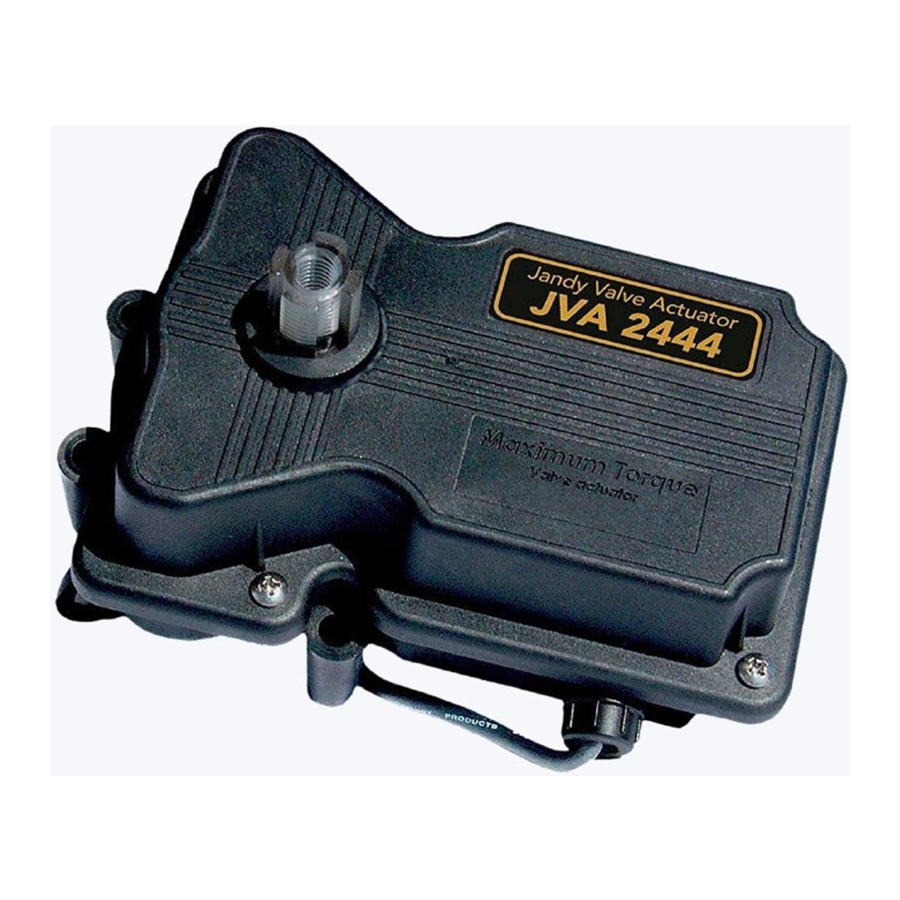
Description
Valve Actuators are designed to meet the needs of today's more advanced, automatic pool equipment. These fully adjustable actuators offer versatile pool/spa automation with easy setups. All actuators work with AquaLink® RS Control Systems and are available in 24 volt units.
| JVA 2444 Specifications | |
| Voltage | 24 VAC |
| Amperage | 0.75 AMPS |
| Cycles | 60 Hz |
Wire
| 3-conductor Common Switch Leg Switch Leg |
JVA Mounting Positions
Standard JVA Position
Standard Plumbing position is with the middle port (B) as the incoming or common port to the valve.

Standard Mounting position is with the main body of the actuator over port B.

NOTE
If the valve(s) are plumbed with port B as the common port (Standard Plumbing) and the main body of the actuator(s) are mounted over port B (Standard Mounting), there is no need to adjust the actuator cams.
Actuator Mounting
JVA's mount directly on all full-size Jandy Pro Series Valves (8 screws on lid). Zodiac recommends motorizing Jandy Pro Series Never Lube® Valves only.
JVA's may be mounted onto valves in any of the four (4) positions in Figure 3.

- Unscrew the locking knob by turning the knob counterclockwise. Remove the locking knob and valve handle.

- For standard valves, remove the four (4) large Phillips head screws from the valve. The location of the screws you remove will determine how the actuator will be mounted (see Figure 4). When installing the large 3" valve, it is not necessary to remove any screws. Use the four mounting bosses provided.
- Turn the actuator over so you can see into the clear actuator shaft. There are four (4) "teeth" on the inside of the shaft. Locate the smallest "tooth" and align this "tooth" with the smallest slot on the valve.

- Place the actuator onto the valve.
- Rotate the actuator while keeping the two shafts engaged until the screw holes on the actuator legs align with the empty screw holes (from step 2) in the valve.

- Use the four (4) large 2" Phillips head screws (included with the JVA) to secure the JVA to the valve.
- Put the valve handle on the actuator shaft. Put the knob on the shaft and tighten (finger tighten only).


Synchronization
Synchronization Methods
If the valve is plumbed in the Standard Plumbingposition and the actuator is mounted in Standard Mounting position, you do not have to change the cam settings from the factory settings. However, you may have to synchronize the cams.
One of the following will occur when the actuator is out of synchronization:
- the actuator will rotate in the wrong direction in relation to its controller (as in a solar heating system)
- one actuator will rotate incorrectly in relation to another actuator (as in pool/spa combination)
Figure 7 illustrates an example of the valves and actuators of a pool/spa combination that are out of synchronization. The valve on the left of the illustration (suction) is plumbed with the spa line on the left side of the valve and the pool line on the right; whereas, the valve on the right of the illustration (return) is plumbed with the pool on the left side of the valve and the spa on the right. In this configuration, if the actuators are activated, one will turn to spa while the other will turn to pool. The actuators will have to be synchronized.

On the actuator that is out of synchronization, flip the toggle switch located on the bottom of the actuator to the ON 2 position (see Figure 8). The toggle positions are marked on the actuator top cover. Retry the system.

Resetting the Cams

Improper cam settings can result in dead heading of the water flow which can cause injury or property damage. Improper cam settings and/or operation will void the warranty.
NOTE
Before resetting cams, if the valve is plumbed in Standard Plumbing position and the actuator is in Standard Mounting position there is no need for resetting the cams (see Figure 9). If a port other than "B" is plumbed as the common port or if the actuator is mounted other than Standard Mounting, the cam setting must be changed so the actuator shaft and the valve diverter rotate properly. Refer to the Cam Setting Chart for proper settings.

- Turn OFF actuator power. Unscrew the locking knob by turning the knob counterclockwise. Remove the locking knob and valve handle.
- Remove the four (4) Phillips head screws that secure the actuator lid and then remove the lid.
![]()
Rotate the actuator shaft so the arrow mark on the top cam aligns with the microswitch actuator (bottom cam arrow mark should also align with the bottom microswitch actuator, see Figure 10). Locate the mounting position for the actuator (as per Figure 9, the mounting position will be either I, II, III, or IV). Next, determine what valve port is the common or inlet port (as per Figure 9, the common port will be either A, B, or C). Then refer to the Cam Setting Chart below to determine what the cam settings should be. For example, if the actuator is in JVA mounting position "I", and the common port on the valve is port "A", the cam settings would be 90° for the top cam and 180° for the bottom.

NOTE
The cam is marked with the arrow at "0", a long hash mark at the 180° position, and 2 short hash marks at the 90° and 270° positions.- To set the cams, rotate the cam(s) until the arrow mark on the cam(s) align with the microswitch actuator.

NOTE
The upper cam stops counterclockwise rotation and the lower cam stops clockwise rotation. - Turn power ON to the actuator and use the toggle switch located on the bottom of the actuator to check rotation. Move the toggle switch to either ON 1 or ON 2. Allow the actuator shaft to move until it stops. Check valve diverter position*, if the position is correct flip the toggle switch in the opposite direction and allow the shaft to stop again. If the stop positions are correct, go to step 6. If they are not, reset the cams until correct.
NOTE
If the actuator does not move in either direction, refer to Section Troubleshooting. - Replace the lid and tighten screws. Replace the handle and locking knob.
NOTE
The end of the handle which has the word OFF embossed on it exactly duplicates the shape of the valve diverter. When the handle is placed on a valve or actuator shaft the word OFF will be directly over the center of the valve diverter.


Cam Setting Chart
NOTE
Before resetting cams, always rotate the actuator shaft so the arrow mark on each cam aligns with the pointer above its microswitch.

*Two Port Valve Settings
Manual Operation
Manual Override
It is sometimes necessary to rotate valve(s) manually, without using the system controller. This occurs when the controller is not accessible/operational or when the spa or pool/spa combination require filling or draining.
There are two (2) methods of manually rotating the JVA; one with power on (system operational) and one with power off (no power to the control system).

To prevent damage to your equipment and to minimize the possibility of any injury resulting from such damage, make sure that the pool filtration pump is OFF BEFORE rotating the valve handle.
Manual Override, Power On
- Move the toggle switch located on the bottom of the actuator to the opposite position (ON 1 switch to ON 2 or vice versa). This will rotate the motor to the opposite position.

- Return the toggle switch to the original position after use.

Manual Override, Power Off
- Move toggle switch located on the bottom of actuator to the OFF (center) position.
- Unscrew (counterclockwise) the locking knob above the handle four (4) full turns.
- Push down on the locking knob (not the handle). This will disengage the gear train and allow the handle, and thus the valve diverter, to be moved to any position.
- To return the actuator to automatic position, pull up on the handle while turning it clockwise or counterclockwise until you feel the shaft slide up into the gear train. Turn the locking knob down (clockwise) until snug.
- Put toggle switch back to the original position.
Maintenance
Actuator
The JVA has three (3) seals which should be lubricated once a year. One o-ring is located on the bottom of the actuator where the plastic shaft exits the housing and two (2) O-rings located in the top cover near where the shaft exits the top of the housing. Use the following steps to lubricate the seals:
- Turn OFF power to the actuator.
- Remove the locking knob and handle.

- Spread a small amount of Jandy Pro Series Lube or other silicone base lubricant around the actuator shaft just above the lock out ring (see Figure 13).
- Reinstall handle and locking knob. Only tighten knob one (1) turn.
- Push down on the locking knob to force the actuator shaft into manual.
- Wipe a small amount of lubricant around the actuator shaft where it protrudes from the bottom of the actuator.
- Turn handle once around to spread the lubricant.
- Pull up on the handle and tighten locking knob.

Valve
NOTE
This section does not apply to Jandy Pro Series Never Lube® Valves and non-positive seal valves. Never Lube Valves and non-positive seal valves can be identified by the absence of a grease cap. Never Lube Valves can also be identified by the name "Never Lube" on the handle.
Since the actuator rotates the valve diverter which redirects the flow of water, it is imperative that the seals and the O-rings within the valve body be lubricated often (at least every three (3) months). Use the following procedure to lubricate the valve diverter seals:
- Turn off all pool/spa equipment.
- Rotate valve handle so the OFF on the handle is over the word GREASE on the valve body.
- Unscrew (counterclockwise) and remove the black cap of the grease fitting.
- Fill cap with lubricant (Jandy Lube).
- Replace cap on fitting and turn in (clockwise) until all of the lubricant has been forced into the valve.
- Use manual operation to move the handle from side to side to spread the lubricant across the seal.
- Reset the valve handle to its original position and start the equipment.
Once a year the valve should be disassembled and the O-ring and valve body inspected for damage.
Thoroughly lubricate the square seal and the O-ring. Reassemble the valve.
Wiring Diagrams
JVA Wiring Schematic 2444

Disconnect power to the system at the main circuit breaker before servicing to avoid risk of electric shock which can result in property damage, severe injury or death. All wiring must be done in accordance with the National Electrical Code® (NEC®), NFPA-70. In Canada, all wiring must be done in accordance with the Canadian Electrical Code (CSA C22.1). All applicable local installation codes and regulations must be followed.
To avoid damage to the equipment and minimize risk of injury, use a properly sized, listed Class 2 transformer for connection to the power supply.
JVA's with Toggle Switch
This diagram is for two (2) JVA 2444s.
To operate more JVA's, additional poles and a higher amperage fuse are needed. Do not double lug the JVA switch leg wires (red and white wires).

* Transformer must be sized for the number of JVA's. Each JVA requires.75 amp. at 24 VAC.

JVA's with Time Clock
This diagram is for a single JVA 2444. To operate more JVA's, additional poles and a higher amperage fuse are needed. Do not double lug the JVA switch leg wires (red and white wires).

* Transformer must be sized for the number of JVA's. Each JVA requires.75 amp. at 24 VAC.
Troubleshooting
All major components, including the power cord, are replaceable without replacing the entire actuator. Each item may be replaced as a separate piece allowing easy infield repair. See Exploded Views and Replacement Kits, for actuator replacement part numbers.
| Problem | Cause | Solution/Check |
| Actuator handle oscillates. | Lack of valve seal lubrication. Obstruction in valve body. | Lubricate valve. Remove actuator and valve lid and inspect. |
| Actuator motor works but the valve diverter does not turn. NOTE On a pool/spa combination, the problem would be spa draining or overflowing. |
|
|
| Actuator motor does not turn. |
|
|
| Actuator rotates in one direction but not back again. |
|
|
| Water inside valve actuator. | Damaged seals. | Replace top lid and grease seals. |
JVA Exploded View and Spare Parts

| Dwg. # | Kit # | Description | Qty. |
| 1 | R0409600 | JVA Gasket and Screw Kit | |
| Gasket O-ring, Screw, #14 x 2" Screw, #8 x 5/8" | 1 2 4 4 | ||
| 2 | R0411500 | Top Housing Kit | |
| Gasket O-ring Screw, #8 x 5/8" Housing, Top | 1 2 4 1 | ||
| 3 | R0408700 | Center Plate Kit | |
| O-ring Screw, #8 x 5/8" Bridge Top Cam (Clear) Bottom Cam (Textured) Microswitch Center Plate Output Shaft, Threaded Spring, JVA | 2 8 1 1 1 2 1 1 1 | ||
| 4 | R0411600 | Gear Kit | |
| Primary Gear Secondary Gear Large Pinion Gear Output Gear Housing, Bottom w/3 Pins | 1 1 1 1 1 | ||
| 5 | R0411800 | Cable Kit, 20' | |
| O-ring, Strain Relief Washer, Strain Relief Cap, Strain Relief Power Cord, 20' w/3-pin Connector | 1 1 1 1 | ||
| 5 | R0411900 | Cable Kit, 75' | |
| O-ring, Strain Relief Washer, Strain Relief Cap, Strain Relief Power Cord, 75' w/3-pin Connector | 1 1 1 1 | ||
| 6 | R0441700 | PCB w/Toggle Switch Kit | |
| PCB Sub-Assy, 24V w/PCB, w/Toggle Switch, Lock Washer and Nut | 1 | ||
| 7 | R0408500 | Motor Kit | |
| Screw, #8 x 5/8" Motor 24V, w/Wire and Connector | 1 1 | ||
| 8 | R0408600 | Cam and Microswitch Kit | |
| Top Cam (Clear) Bottom Cam (Textured) Microswitch | 1 1 2 | ||
Safety Information
FOR YOUR SAFETY - This product must be installed and serviced by a contractor who is licensed and qualified in pool equipment by the jurisdiction in which the product will be installed where such state or local requirements exist. The maintainer must be a professional with sufficient experience in pool equipment installation and maintenance so that all of the instructions in this manual can be followed exactly. Before installing this product, read and follow all warning notices and instructions that accompany this product. Failure to follow warning notices and instructions may result in property damage, personal injury, or death. Improper installation and/or operation will void the warranty.
Improper installation and/or operation can create unwanted electrical hazard which can cause serious injury, property damage, or death.
IMPORTANT SAFETY INSTRUCTIONS PERTAINING TO A RISK OF FIRE, ELECTRIC SHOCK, OR INJURY TO PERSONS
READ AND FOLLOW ALL INSTRUCTIONS
When installing and using this electrical equipment, basic safety precautions should always be followed, including the following:
This manual contains important information about the installation, operation and safe use of this product. This information should be given to the owner/operator of this equipment.
This product must be installed and serviced by professionals who are qualified in pool/spa product installation and service. Improper installation and/or operation can create an unwanted electrical hazard which can cause serious injury, property damage, or death. Improper installation and/or operation will void the warranty.
Disconnect power to the system at the main circuit breaker before servicing to avoid risk of electric shock which can result in property damage, severe injury or death. All wiring must be done in accordance with the National Electrical Code® (NEC®), NFPA-70. In Canada, all wiring must be done in accordance with the Canadian Electrical Code (CSA C22.1). All applicable local installation codes and regulations must be followed.
To ensure best customer service and tracking of warranty, we recommend you register your product at:
Jandy.com/Registration (USA)
Jandy.ca/Registration (Canada)
Zodiac Group Australia.
219 Woodpark Road
Smithfield, NSW AU 2164
1.800.688.552
www.Zodiac.com.au
Zodiac Pool Systems, Inc.
2620 Commerce Way, Vista, CA 92081
1.800.822.7933
www.ZodiacPoolSystems.com
Documents / Resources
References
![jandy.com]() http://jandy.com/Registration
http://jandy.com/Registration![jandy.ca]() http://jandy.ca/Registration
http://jandy.ca/RegistrationWorld Leader In Pool Maintenance | Zodiac Australia
![www.zodiacpoolsystems.com]() Zodiac Pool Systems United States | Zodiac Pool Systems
Zodiac Pool Systems United States | Zodiac Pool Systems

Download manual
Here you can download full pdf version of manual, it may contain additional safety instructions, warranty information, FCC rules, etc.
Advertisement


Need help?
Do you have a question about the Pro Series and is the answer not in the manual?
Questions and answers