
Related Manuals for Korenix JetNet 3008


Summary of Contents for Korenix JetNet 3008
- Page 1 JetNet 3008 v3 JetNet 3008f v3 Industrial 8-port Ethernet Switch User’s Manual Version:1.2 Date: 17-Oct-2019...
-
Page 2: Table Of Contents
Content Introduction ..............1 1-1. Features..............2 1-2. Packing List..............2 Hardware Description..........3 2.1. Dimensions ............3 Front Panel ............4 2-3. Bottom View............4 2-4. LED Indicators ............5 2-5. Ports ..............6 Mounting Installation ........... 7 DIN-Rail Mounting ............... 7 Hardware Installation .......... -
Page 3: Federal Communications Commission (Fcc) Statement
Federal Communications Commission (FCC) Statement This equipment has been tested and found to comply with the limits for a Class A digital device, pursuant to Part 15 of the FCC Rules. These limits are designed to provide reasonable protection against harmful interference when the equipment is operated in a commercial environment. -
Page 4: Introduction
The combination of enhanced network features and rugged specs make the JetNet 3008 V3 /JetNet 3008f V3 become your best entry-level networking solution in industrial deployments. -
Page 5: Features
This session will introduce following information of JetNet 3008 for your reference. 1. Features 2. Packing list 1-1. Features ◼ 8 10/100TX ports – JetNet 3008 ◼ 6 10/100TX, plus 2 100FX in Multi-mode or Single-mode – JetNet 3008f ◼... -
Page 6: Hardware Description
2-4. LEDs of system and port 2-5. Connectors 2.1. Dimensions JetNet 3008 / JetNet 3008f 8-port Industrial Fast Ethernet Rail Switch dimensions are 120 mm (H) x 55 mm (W) x 108 mm (D), detail mechanical design drawings are attached as following:... -
Page 7: Front Panel
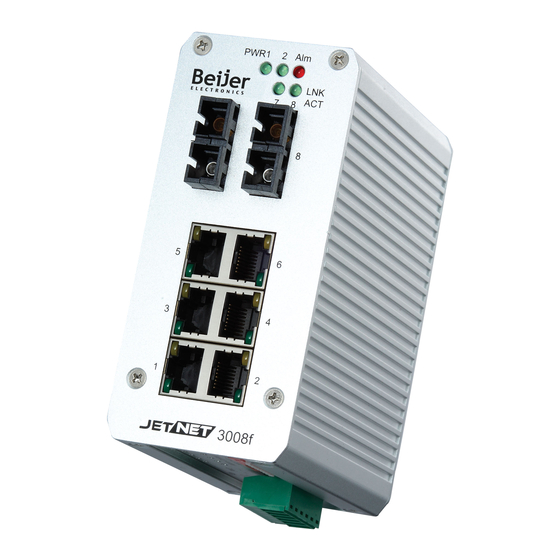
2-2 Front Panel The Front Panel of the JetNet 3008/JetNet 3008f Industrial 8-port Fast Ethernet Switch is shown in Figure A. Figure A. Front Panel of the JetNet 3008 / JetNet 3008f. 2-3. Bottom View The bottom view of the JetNet 3008/JetNet 3008f Industrial 8-port Ethernet Switch consists of one 6-pin removable terminal block connector for two DC power inputs and event alarm output. -
Page 8: Led Indicators
Figure B. Bottom view of the JetNet 3008/ JetNet 3008f 2-4. LED Indicators There are some system diagnostic LEDs and Ethernet Port LEDs located on the front panel of JetNet3008 / JetNet 3008f Industrial 8-port Ethernet Switch. These LED indicators provide administrators with real-time system status. -
Page 9: Ports
TX device. Table 1 2-5. Ports RJ-45 ports (Auto MDI/MDIX): JetNet 3008 has eight 10/100 Mbps auto-sensing RJ-45 ports for 10Base-T or 100Base-TX device connection and JetNet 3008f has six 10/100Mbps RJ-45 ports and two 100Mbps fiber ports for multi-mode or single-mode fiber cable in SC type connector. -
Page 10: Mounting Installation
3. Mounting Installation DIN-Rail Mounting The DIN-Rail clip is already attached on the rear side of JetNet 3008/ JetNet 3008f. JetNet 3008 series supports EN 50022 standard DIN Rail, in the following diagram includes the dimension of EN 55022 DIN Rail for your reference. - Page 11 4. To remove the JetNet 3008/ JetNet 3008f-m from the track, reverse the steps above.
-
Page 12: Hardware Installation
4. Hardware Installation The following figure illustrates a typical application of JetNet 3008 / JetNet 3008f in field site. It includes Enterprise communication backbone network, Factory communication, field site communication and field site control layers. The control equipments access and report production information through the JetNet 3008 or JetNet 3008f and uplink to factory communication level by fiber or copper which with network redundancy. -
Page 13: Wiring The Dc Power Inputs
4-1. Wiring the DC Power Inputs Follow the steps below to wire JetNet 3008’s / JetNet 3008f’s dual DC power inputs. [Note] The suitable electric wire ranges is from 12 to 24 AWG. V- V+ V- V+ 1. Insert the positive and negative wires into the V+ and V- contacts respectively of the terminal block connector 2. -
Page 14: Wiring The Alarm Relay
4-2. Wiring the Alarm Relay JetNet 3008 /JetNet 3008f provides one dry relay output for power or port link event; the alarm relay is “Normal open” and form a close circuit The maximum current is 1A. In the following diagram shows how to make an alarm circuit. -
Page 15: Wiring Earth Grounding
The feature is controlled by digital control circuits and effect immediately without system reset when DIP SWITCH changed. On the bottom side of JetNet 3008 and JetNet 3008f, there is one 9-Pin DIP SWITCH for alarm control. By inserting the port and power wiring, setting the DIP SWITCH of the intended Alarm to “ON”, the relay output... - Page 16 The DIP SWITCH Setting for the Alarm Relay Output is show as following table. Pin No. # Status Description To enable port link down alarm at this port. P1 to P8 (Pin1 ~8) To disable port link down alarm at this port. To enable power failure alarm.
-
Page 17: Cabling
4-5. Cabling The UTP cable connection between the JetNet 3008 and the attached devices (switches, hubs, workstations, etc.) must be less than 100 meters (328 ft.) long. The transmission distance of JetNet 3008f is depends on the type of fiber transceiver model and the attenuation of optical fiber cable. -
Page 18: System Power-On And Testing
1. Take your JetNet 3008 / JetNet 3008f Industrial 8-port Fast Ethernet Switch out from the box. 2. To place the JetNet 3008 on the DIN-Rail track, refer to the Mounting Installation section. 3. Pull the terminal block off the JetNet 3008 and wire the power lines. - Page 19 8. Check the port status LED indicator (blinking green) on the JetNet3008 to see if the network connection is established successfully. 9. Power on your host PC, make an Ethernet connection to JetNet 3008 and check the connected port is link up ;The connection diagram shown as below: 10.
- Page 20 address 192.168.1.1 as an example. 11. Repeat step 10 to make sure that the connection of each device connected to the JetNet3008 is successfully established. 12. Power on the PC host, activate the Command Line mode, and ping the connected Ethernet device by typing “ping 192.168.1.1 –t” command to see if it will respond.
- Page 21 successfully connected to power sources. When PWR1 fails, the LED for PWR1 will go out. At that moment, if the ping command is still being replied to, then it proves that the redundant power input function works normally.
-
Page 22: Packet Forwarding And Filtering Ability
VLAN Tag and TCP/IP TOS of IPv4 and IPv6. IEEE 802.1Q tag based CoS The JetNet 3008/ 3008f will examine the 3 bits of priority field carried by a VLAN tag and map it to the corresponding priority. A packet with priority field ranging from 0 to 3 will be treated as a low priority packet, and will be stored in low priority queue. - Page 23 The JetNet 3008/3008f also provides the IP layer QoS function by recognizing the priority octet and mapping it to the corresponding priority. For an IPv4 packet, it is embedded in the TOS (type of Service) Octet. The first 3 bits are used to define a precedence. The higher the value, the more important the IP packet is, in case of congestion, the router would drop the low-priority packets first.
-
Page 24: Trouble Shooting
6. Trouble shooting ◼ Make sure you are using the correct DC power suppliers (DC12 to 48 V). Do not use power suppliers with DC output over 48V. It may damage devices. ◼ Select Ethernet cables with specifications suitable for your applications to set up your systems. -
Page 25: Technical Specifications
7. Technical Specifications Technology Standard IEEE 802.3 10Base-T Ethernet IEEE 802.3u 100Base-TX /100Base-FX Fast Ethernet IEEE 802.3x Flow Control and Back-pressure IEEE 802.1p Class of Service (CoS) System Performance Store and Forward Technology with 2.0Gbps Switch Fabric Switch Technology Mega packets per second, 64 bytes packet size System Throughput 14,880pps for 10Base-T 148,800pps for 100Base-TX... - Page 26 55(W) x 120(H) x 108 (D) / with DIN Rail Clip JetNet 3008 V3: 0.555Kg Weight JetNet 3008f V3:0.575kg Environmental -25~70℃ ( JetNet 3008); -40~75 ℃ (JetNet 3008-w) Operating Temperature -10~70℃ ( JetNet 3008f); -40~75 ℃ (JetNet 3008f-w) Note-1 Operating Humidity 0% ~ 90%, non-condensing -40 ~ 85 ℃...
- Page 27 Revision History Edition Date Modifications V1.0 Nov-2011 Modify from 3008 V2 user manual. Relay 1A, 24V -> 0.5A, 24V ( Drawing) Remove – CD User Manual V1.1 26-Jun-2013 V1.2 17-Oct-2019 Updated Relay 1A, 24V...
Need help?
Do you have a question about the JetNet 3008 and is the answer not in the manual?
Questions and answers