Korenix JetNet 3018G User Manual
Industrial managed ethernet switch
Hide thumbs
Also See for JetNet 3018G:
- Quick installation manual (5 pages) ,
- Quick installation manual (2 pages)

Related Manuals for Korenix JetNet 3018G


Summary of Contents for Korenix JetNet 3018G
- Page 1 Korenix JetNet 3018G/4518/5012G/5018G/5018G 2.0 Industrial Managed Ethernet Switch User Manual Manual v1.4 Firmware v1.3 July, 2012 www.korenix.com...
-
Page 2: User Manual
Korenix JetNet 3018G/4518/5012G/5018G/5018G 2.0 Industrial Managed Ethernet Switch User Manual Copyright Notice Copyright 2006-2012 Korenix Technology Co., Ltd. All rights reserved. Reproduction in any form or by any means without permission is prohibited. - Page 3 Federal Communications Commission (FCC) Statement This equipment has been tested and found to comply with the limits for a Class A digital device, pursuant to Part 15 of the FCC Rules. These limits are designed to provide reasonable protection against harmful interference when the equipment is operated in a commercial environment.
-
Page 4: Table Of Contents
4.12 Device Front Panel ..................... 133 4.13 Save to Flash ....................134 4.14 Logout ......................135 Appendix ........................136 Korenix SFP family ..................136 Korenix Private MIB ..................138 ..................ModBus TCP /IP ..................Revision History About Korenix ....................151... -
Page 5: Introduction
Gigabit ports. With fewer unit installation capability, the access ports share wider on-chip backplane, faster local transmission latency, efficient upstream transmission. The summary of the model list are as below. The JetNet 3018G is gigabit plug-and-play Ethernet switch. The JetNet 4518/5012G/5018G/5018G v2.0 is managed switch which supports abundant software features and can be managed through a single management agent. - Page 6 Gigabit SX, LX, LHX, ZX and XD for several connections and distances. The on board gigabit port of the JetNet 3018G always acts as uplink port or server port, they are much important than other ports. The JetNet 3018G provides 2 Digital Output to indicate the alarm when gigabit port link failure.
-
Page 7: Major Features
• 2 Relay Outputs indicate Gigabit port Link Failure (JetNet 3018G) or configured other failures by software (JetNet 4518/5012G/5018G/5018G v2.0.0) • IEEE 802.1p Quality of Service (QoS) compliant (JetNet 3018G, the Tag Priority ID is as following: Higher (6,7), High (4,5), Low (0,3), Lowest (1,2)) •... -
Page 8: Hardware Installation
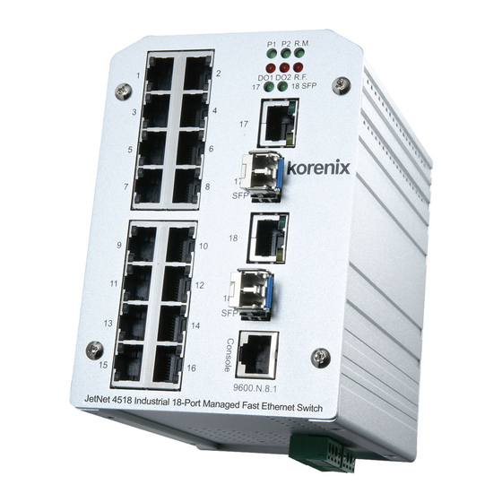
(JetNet 3018G/5012G/5018G supports Gigabit SFP only. JetNet 4518-w supports 100M SFP only. JetNet 5018G v2.0 supports both 100M and Gigabit SFP) JetNet 3018G does not support R.M. and R.F. LED. The RO 1 indicates gigabit port 17 link down/failure, the RO 2 indicates gigabit port 18 link down/failure. - Page 9 Figure of the JetNet 3018G Bottom view of the JetNet 3018G...
- Page 10 Figure of the JetNet 4518/5018G/5018G v2.0 Figure of the JetNet 5012G The Bottom dimension is the same as the JetNet 3018G. Besides the DIP switch on JetNet 3018G, the other placement of JetNet 4518, 5018G and 5012G is the same as JetNet 3018G.
-
Page 11: Wiring Power Inputs
UI. JetNet 3018G: In JetNet 3018G, the Digital Output indicates gigabit port 17 and 18 link down or failure. Click the equipped DIP 1 to ON to enable the port 17 link failure DO alarm, click the DIP 2 to ON to enable the port 18 link failure DO alarm. -
Page 12: Wiring Fast Ethernet Ports
UI will show Unknown vendor type when choosing the SFP which is not certificated by Korenix. The JetNet 3018G/5012G/5018G support Gigabit SFP transceiver, JetNet 4518 supports 100M SFP transceiver, the JetNet 5018G v2.0 supports both 100M and 1000M SFP. The types of the SFP transceivers include single-/multi-mode fiber, the support range is from 550m to 120KM depends on the capability of the plugged transceiver. -
Page 13: Wiring Combo Ports
JetNet 3018G/5012G/5018G/5018G v2.0 The JetNet 3018G/5012G/5018G/5018G v2.0 include 2 Gigabit RJ-45/SFP Combo ports. The port number of the JetNet 3018G/5018G/5018G v2.0 is port 17 and 18. The port number of the JetNet 5012G is port 11 and 12. The speed of the gigabit Ethernet copper port supports 10Base-TX, 100Base-TX and 1000Base-T. -
Page 14: Din-Rail Mounting Installation
buy a new one. The Pin assignment spec is listed in the appendix. DIN-Rail Mounting Installation The DIN-Rail clip is already attached to the JetNet Switch when packaged. If the DIN-Rail clip is not screwed on the JetNet Switch, follow the instructions and the figure below to attach DIN-Rail clip to JetNet Switch. -
Page 15: Wall Mounting Installation
Lightly push the bottom of DIN-Rail clip into the track. Check if DIN-Rail clip is tightly attached on the track. To remove JetNet Switch from the track, reverse the steps above. 2.10 Wall Mounting Installation Follow the steps below to install JetNet Switch with the wall mounting plate. 1. -
Page 16: Safety Warming
2. Place the wall mounting plate on the rear panel of JetNet Switch. 3. Use the screws to tighten the wall mounting plate onto JetNet Switch. 4. Use the hook holes at the corners of the wall mounting plate to hang JetNet Switch onto the wall. - Page 17 “Laite on liitettava suojamaadoitus-koskettimilla varustettuun pistorasiaan” „Apparatet ma tilkoples jordet stikkontakt“ ”Apparaten skall anslutas till jordat uttag”...
-
Page 18: Preparation For Management
3.3 Preparation for Telnet console Preparation for Serial Console In JetNet Managed Switch package, Korenix attached one RS-232 DB-9 to DB-9/RJ-45 console cable. Please attach RS-232 DB-9 connector to your PC COM port, connect the other end to the Console port of the JetNet Managed Switch. If you lose the cable, please follow the console cable PIN assignment to find one. -
Page 19: Preparation For Web Interface
Interface for web management. 3.2.1 Web Interface Korenix web management page is developed by JAVA. It allows you to use a standard web-browser such as Microsoft Internet Explorer, or Mozila, to configure and interrogate the switch from anywhere on the network. - Page 20 3.2.2 Secured Web Interface Korenix web management page also provides secured management HTTPS login. All the configuration commands will be secured and will be hard for the hackers to sniff the login password and configuration commands.
-
Page 21: Preparation For Telnet Console
3.3.1 Telnet Korenix JetNet managed Switch supports Telnet console. You can connect to the switch by Telnet and the command lines are the same as what you see by RS232 console port. Below are the steps to open Telnet connection to the switch. - Page 22 3.3.2 SSH (Secure Shell) Korenix JetNet Managed Switch also support SSH console. You can remotely connect to the switch by command line interface. The SSH connection can secure all the configuration commands you sent to the switch. SSH is a client/server architecture while JetNet Managed Switch is the SSH server.
- Page 23 3. After few seconds, the SSH connection to JetNet Managed Switch is opened. You can see the login screen as the below figure. 4. Type the Login Name and its Password. The default Login Name and Password are admin / admin. 5.
-
Page 24: Feature Configuration
Then you can remotely connect to its embedded HTML web pages or Telnet console. Korenix web management page is developed by JAVA. It allows you to use a standard web-browser such as Microsoft Internet Explorer, or Mozila, to configure and interrogate the switch from anywhere on the network. -
Page 25: Command Line Interface Introduction
Command Line Interface Introduction The Command Line Interface (CLI) is the user interface to the switch’s embedded software system. You can view the system information, show the status, configure the switch and receive a response back from the system by keying in a command. There are some different command modes. - Page 26 Global Configuration Mode: Press configure terminal in privileged EXEC mode. You can then enter global configuration mode. In global configuration mode, you can configure all the features that the system provides you. Type interface IFNAME/VLAN to enter interface configuration mode, exit to leave. ? to see the command list.
- Page 27 Type exit to leave. Type ? to see the command list Available command lists of the (port) Interface configuration mode. Switch(config)# interface fa1 Switch(config-if)# acceptable Configure 802.1Q acceptable frame types of a port. auto-negotiation Enable auto-negotiation state of a given port description Interface specific description duplex...
- Page 28 Summary of the 5 command modes. Command Main Function Enter and Exit Method Prompt Mode User EXEC This is the first level of access. Enter: Login successfully Switch> User can ping, telnet remote Exit: exit to logout. device, and show some basic Next mode: Type enable to information enter privileged EXEC mode.
- Page 29 Here are some useful commands for you to see these available commands. Save your time in typing and avoid typing error. ? To see all the available commands in this mode. It helps you to see the next command you can/should type as well. Switch(config)# interface (?) IFNAME Interface's name vlan...
-
Page 30: Basic Setting
Basic Setting The Basic Setting group provides you to configure switch information, IP address, User name/Password of the system. It also allows you to do firmware upgrade, backup and restore configuration, reload factory default, and reboot the system. Following commands are included in this group: 4.2.1 Switch Setting 4.2.2 Admin Password 4.2.3 IP Configuration... - Page 31 System OID: The SNMP object ID of the switch. You can follow the path to find its private MIB in MIB browser. (Note: When you attempt to view private MIB, you should compile private MIB files into your MIB browser first.) System Description: JetNet (Model name) Industrial Managed Switch is the name of this product.
- Page 32 4.2.3 IP Configuration This function allows users to configure the switch’s IP address settings. DHCP Client: You can select to Enable or Disable DHCP Client function. When DHCP Client function is enabled, an IP address will be assigned to the switch from the network’s DHCP server.
- Page 33 also can click the button “Get Time from PC” to get PC’s time setting for switch. After click the “Get Time from PC” and apply the setting, the System time display the same time as your PC’s time. NTP client: Select the Time Setting Source to NTP client can let device enable the NTP client service.
- Page 34 19 (GMT-03:00) Brasilia 20 (GMT-03:00) Buenos Aires, Georgetown 21 (GMT-03:00) Greenland 22 (GMT-02:00) Mid-Atlantic 23 (GMT-01:00) Azores 24 (GMT-01:00) Cape Verde Is. 25 (GMT) Casablanca, Monrovia 26 (GMT) Greenwich Mean Time: Dublin, Edinburgh, Lisbon, London 27 (GMT+01:00) Amsterdam, Berlin, Bern, Rome, Stockholm, Vienna 28 (GMT+01:00) Belgrade, Bratislava, Budapest, Ljubljana, Prague 29 (GMT+01:00) Brussels, Copenhagen, Madrid, Paris 30 (GMT+01:00) Sarajevo, Skopje, Sofija, Vilnius, Warsaw, Zagreb...
- Page 35 Click the check box to enable the Daylight Saving Function as the setting of start and end week or disable it. Daylight Saving Start and Daylight Saving End: the functions allows user to selects and apply the daylight saving start week and end week by monthly basis. Once you finish your configuration, click on Apply to apply your configuration.
- Page 36 4.2.6 DHCP Server You can select to Enable or Disable DHCP Server function. JetNet Managed Switch will assign a new IP address to link partners. DHCP Server configuration After selecting to enable DHCP Server function, type in the Network IP address for the DHCP server IP pool, Subnet Mask, Default Gateway address and Lease Time for client.
- Page 37 Manual Binding: JetNet Managed Switch provides a MAC address and IP address binding and removing function. You can type in the specified IP and MAC address, then click Add to add a new MAC&IP address binding rule for a specified link partner, like PLC or any device without DHCP client function.
- Page 38 4.2.7 Backup and Restore With Backup command, you can save current configuration file saved in the switch’s flash to admin PC or TFTP server. This will allow you to go to Restore command later to restore the configuration file back to the switch. Before you restore the configuration file, you must place the backup configuration file in the PC or TFTP server.
- Page 39 4.2.8 Firmware Upgrade In this section, you can update the latest firmware for your switch. Korenix provides the latest firmware in Korenix Web site. The new firmware may include new features, bug fixes or other software changes. We’ll also provide the release notes for the update as well. For technical viewpoint, we suggest you use the latest firmware before installing the switch to the customer site.
- Page 40 Please remind the attached users before you reboot the switch. Figure 4.2.8.1 Main UI of Firmware Upgrade There are 2 modes for users to backup/restore the configuration file, Local File mode and TFTP Server mode. Local File mode: In this mode, the switch acts as the file server. Users can browse the target folder and then type the file name to backup the configuration.
- Page 41 Figure 4.2.8.4 Error Message due to the file error or not a firmware for the switch. Before upgrading firmware, please check the file name and switch model name first and carefully. Korenix switch provide protection when upgrading incorrect firmware file, the system would not crash even download the incorrect firmware. Even we have the protection, we still ask you don’t try/test upgrade incorrect firmware, the unexpected event...
- Page 42 Type the IP address of TFTP Server and Firmware File Name. Then click on Upgrade to start the process. After finishing transmitting the firmware, the system will copy the firmware file and replace the firmware in the flash. The CLI show …… until the process is finished. 4.2.9 Factory Default In this section, you can reset all the configurations of the switch to default setting.
- Page 43 4.2.10 System Reboot System Reboot allows you to reboot the device. Some of the feature changes require you to reboot the system. Click on Reboot to reboot your device. Note: Remember to click on Save button to save your settings. Otherwise, the settings you made will be gone when the switch is powered off.
- Page 44 JetNet4518 (System Name, Loader Version : 1.0.0.3 Firmware Version : 1.1.22-20100927-12:11:00 Location, Contact; Copyright 2006-2009 Korenix Technology Co., Ltd. System Firmware and SWITCH# show hardware mac Loader version, MAC MAC Address : 001277FF1357 address, LED status) SWITCH# show hardware led led information...
- Page 45 SWITCH# show interface vlan1 Display interface vlan1 is up, line protocol detection is disabled (Management VLAN, index 22 metric 1 mtu 1500 <…> HWaddr: 00:12:77:ff:13:57 Running-Config) inet 192.168.10.1/24 broadcast 192.168.10.255 ……….. SWITCH# show running-config ……… interface vlan1 ip address 192.168.10.8/24 no shutdown ip route 0.0.0.0/0 192.168.10.254/24 Time Setting...
- Page 46 Type the maximum MTU to enable Jumbo Frame: Jumbo Frame SWITCH(config)# system mtu <64-9216> bytes (with VLAN tag) Switch(config)# system mtu 9216 Disable Jumbo Frame: SWITCH(config)# no system mtu SWITCH# show system mtu Display System MTU size is 9216 bytes After disabled Jumbo Frame: SWITCH# show system mtu System MTU size is 1522 bytes...
- Page 47 replace Switch(config-dhcp)# ip dhcp relay information policy drop <cr> Switch(config-dhcp)# ip dhcp relay information policy keep <cr> Switch(config-dhcp)# ip dhcp relay information policy replace <cr> Switch(config-dhcp)# ip dhcp helper-address DHCP Relay – IP A.B.C.D Helper Address Switch(config-dhcp)# ip dhcp helper-address 192.168.10.200 Switch(config-dhcp)# ip dhcp reset Reset DHCP Settings <cr>...
- Page 48 Firmware Upgrade Switch# archive download-sw /overwrite tftp 192.168.10.33 Firmware Upgrade JN5018G.bin Firmware upgrading, don't turn off the switch! Tftping file JN5018G.bin Firmware upgrading ......................................Firmware upgrade success!! Rebooting..Factory Default Switch# reload default-config file Factory Default System Reboot Switch# reboot Reboot...
-
Page 49: Port Configuration
Port Configuration Port Configuration group enables you to enable/disable port state, or configure port auto-negotiation, speed, and duplex, flow control, rate limit control and port aggregation settings. It also allows you to view port status and aggregation information. Following commands are included in this group: 4.3.1 Understand the port mapping 4.3.2 Port Control 4.3.3 Port Status... - Page 50 In Speed/Duplex column, you can configure port speed and duplex mode of this port. Below are the selections you can choose: Fast Ethernet Port 1~N (fa1~faN): AutoNegotiation, 10M Full Duplex(10 Full), 10M Half Duplex(10 Half), 100M Full Duplex(100 Full) and 100M Half Duplex(100 Half). Gigabit Ethernet Port 1~N (gi1~giN): AutoNegotiation, 10M Full Duplex(10 Full), 10M Half Duplex(10 Half), 100M Full Duplex(100 Full), 100M Half Duplex(100 Half), 1000M Full Duplex(1000 Full), 1000M Half Duplex(1000 Half).
- Page 51 Note: Most of the SFP transceivers provide vendor information which allows your switch to read it. The UI can display vendor name, wave length and distance of all Korenix SFP transceiver family. If you see Unknown info, it may mean that the SFP transceiver is not certified by Korenix Quality system, and the vendor information won’t display except other...
- Page 52 4.3.4 Rate Control Rate limiting is a form of flow control used to enforce a strict bandwidth limit at a port. You can program separate transmit (Egress Rule) and receive (Ingress Rule) rate limits at each port, and even apply the limit to certain packet types as described below.
- Page 53 IEEE standard, 802.3ad. The aggregated ports can interconnect to the other switch which also supports Port Trunking. Korenix Supports 2 types of port trunking. One is Static Trunk, the other is 802.3ad. When the other end uses 802.3ad LACP, you should assign 802.3ad LACP to the trunk.
- Page 54 Group ID: Display Trunk 1 to Trunk 5 set up in Aggregation Setting. Type: Static or LACP set up in Aggregation Setting. Aggregated: When LACP links well, you can see the member ports in Aggregated column. Individual: When LACP is enabled, member ports of LACP group which are not connected to correct LACP member ports will be displayed in the Individual column.
- Page 55 Port Status Switch# show interface fa1 Port Status Interface fastethernet1 Administrative Status : Enable Operating Status : Connected Duplex : Full Speed : 100 MTU: 1518 Flow Control :off Default Port VLAN ID: 1 Ingress Filtering : Disabled Acceptable Frame Type : All Port Security : Disabled Auto Negotiation : Disable Loopback Mode : None...
- Page 56 multicast Multicast packets Type) SWITCH(config)# storm-control broadcast ? <0-100000> Rate limit value 0~100000Kbyte/sec SWITCH(config)# storm-control broadcast 10000 limit_rate = 10000 Set rate limit for Broadcast packets. SWITCH(config)# storm-control multicast 1000 limit_rate = 1000 Set rate limit for Multicast packets. SWITCH(config)# storm-control dlf 1000 limit_rate = 1000 Set rate limit for Destination Lookup Failue packets.
- Page 57 long specifies a long timeout value (default) short specifies a short timeout value SWITCH(config-if)# lacp timeout short Set lacp port timeout ok. Switch(config)# trunk group 2 fa6-7 Static Trunk Trunk group 2 enable ok! Failure to configure due to the group ID is existed. SWITCH(config)# trunk group 1 fa11-12 Can't set trunk group 1 enable! The group 1 is a lacp enabled group!
-
Page 58: Network Redundancy
MultiRing Technology. The Ring ports can be LACP/Port Trunking ports, after aggregated ports to a group, the group of ports can act as the Ring port of the Ring. This is Korenix Pattened TrunkRing Technology. Advanced Rapid Dual Homing(RDH) technology also facilitates JetNet switch to connect with a core managed switch easily and conveniently. - Page 59 4.4.1 STP Configuration This page allows select the STP mode and configuring the global STP/RSTP Bridge Configuration. The STP mode includes the STP, RSTP, MSTP and Disable. Please select the STP mode for your system first. The default mode is RSTP enabled. After select the STP or RSTP mode, continue to configure the global Bridge parameters for STP and RSTP.
- Page 60 Since different RSTP aware switches may have their own mechanism to calculate the message age. So that this is most possibly occurred when interoperate different vendors’ RSTP aware switches together. The maximum volume of the Korenix RSTP domain is 23, configure the MAX Age lower than 23 is recommended.
- Page 61 decides which port should be blocked by priority in a LAN. Link Type: There are 3 link types for your selection-Auto, P2P and Share. Some of the rapid state transitions that are possible within RSTP depend upon whether the port of concern can only be connected to another bridge (i.e. it is served by a point-to-point LAN segment), or if it can be connected to two or more bridges (i.e.
- Page 62 4.4.3 RSTP Info This page allows you to see the information of the root switch and port status. Root Information: You can see root Bridge ID, Root Priority, Root Port, Root Path Cost and the Max Age, Hello Time and Forward Delay of BPDU sent from the root switch. Port Information: You can see port Role, Port State, Path Cost, Port Priority, Oper P2P mode, Oper edge port mode and Aggregated(ID/Type).
- Page 63 The figure shows there are 2 VLANs/MSTP Instances and each instance has its Root and forwarding paths. A Common Spanning Tree (CST) interconnects all adjuacent MST regions and acts as a virtual bridge node for communications with STP or RSTP nodes in the global network. MSTP connects all bridges and LAN segments with a single Common and Internal Spanning Tree (CIST).
- Page 64 After enabled MSTP mode, then you can go to the MSTP Configuraiton pages. MSTP Region Configuration This page allows configure the Region Name and its Revision, mapping the VLAN to Instance and check current MST Instance configuration. The network can be divided virtually to different Regions.
- Page 65 Instance ID: Select the Instance ID, the available number is 1-15. VLAN Group: Type the VLAN ID you want mapping to the instance. Instance Priority: Assign the priority to the instance. After finish your configuration, click on Add to apply your settings. Current MST Instance Configuration This page allows you to see the current MST Instance Configuration you added.
- Page 66 Path Cost: Enter a number between 1 and 200,000,000. This value represents the “cost” of the path to the other bridge from the transmitting bridge at the specified port. Priority: Enter a value between 0 and 240, using multiples of 16. This is the value that decides which port should be blocked by priority in a LAN.
- Page 67 Multiple Super Ring (MSR) technology is Korenix’s 3 generation Ring redundancy technology. This is patented and protected by Korenix and is used in countries all over the world. MSR ranks the fastest restore and failover time in the world, 0 ms for restore and about milliseconds level for failover for 100Base-TX copper port.
- Page 68 Ring Port2: Assign another port for ring connection Path Cost: Change the Path Cost of Ring Port2 Rapid Dual Homing: Rapid Dual Homing is an important feature of Korenix 3 generation Ring redundancy technology. When you want to connect multiple RSR or form a redundant topology with other vendors, RDH could allow you to have maximum 7 multiple links for redundancy without any problem.
- Page 69 4.4.8 Ring Info This page shows the MSR information. ID: Ring ID. Version: which version of this ring, this field could be Rapid Super Ring, Super Ring, or Any Ring Role: This Switch is RM or nonRM Status: If this field is Normal which means the redundancy is approved. If any one of the link in this Ring is broken, then the status will be Abnormal.
- Page 70 Bridge Priority Switch(config)# spanning-tree priority <0-61440> valid range is 0 to 61440 in multiple of 4096 Switch(config)# spanning-tree priority 4096 Bridge Times Switch(config)# spanning-tree bridge-times (forward Delay) (max-age) (Hello Time) Switch(config)# spanning-tree bridge-times 15 20 2 This command allows you configure all the timing in one time. Forward Delay Switch(config)# spanning-tree forward-time <4-30>...
- Page 71 Instance Vlans Mapped -------- -------------------------------------- 1,4-4094 Config HMAC-MD5 Digest: 0xB41829F9030A054FB74EF7A8587FF58D ------------------------------------------------ Remove Region Switch(config-mst)# no Name name name configure revision revision configure instance the mst instance Switch(config-mst)# no name Remove Instance Switch(config-mst)# no instance example <1-15> target instance number Switch(config-mst)# no instance 2 Show Pending MST Switch(config-mst)# show pending Configuration...
- Page 72 Root Times : max-age 20, hello-time 2, forward-delay 15 Bridge Address : 0012.77ee.eeee Priority : 32768 Bridge Times : max-age 20, hello-time 2, forward-delay 15 BPDU transmission-limit : 3 Port Role State Cost Prio.Nbr Type Aggregated ------ ---------- ---------- -------- ---------- ------------ ------------ fa1 Designated Forwarding 200000 128.1...
- Page 73 Port Role State Cost Prio.Nbr Type ------ ---------- ---------- -------- ---------- ------------------ fa1 Designated Forwarding 200000 128.1 P2P Internal(MSTP) Internal(MSTP) fa2 Designated Forwarding 200000 128.2 P2P ###### MST01 vlans mapped: 2 Bridge address 0012.77ee.eeee priority 32768 (sysid 1) Root this switch for MST01 Port Role State...
- Page 74 default set default Switch(config)# super-ring priority 100 Ring Port Switch(config-multiple-super-ring)# port IFLIST Interface list, ex: fa1,fa3-5,gi8-10 cost path cost Switch(config-multiple-super-ring)# port fa1,fa2 Ring Port Cost Switch(config-multiple-super-ring)# port cost <0-255> valid range is 0 or 255 default set default (128)valid range is 0 or 255 Switch(config-multiple-super-ring)# port cost 100 <0-255>...
-
Page 75: Vlan
VLAN A Virtual LAN (VLAN) is a “logical” grouping of nodes for the purpose of limiting a broadcast domain to specific members of a group without physically grouping the members together. That means, VLAN allows you to isolate network traffic so that only members of VLAN could receive traffic from the same VLAN members. - Page 76 VLAN Configuration group enables you to Add/Remove VLAN, configure port Ingress/Egress parameters and view VLAN table. Following commands are included in this group: 4.5.1 VLAN Port Configuration 4.5.2 VLAN Configuration 4.5.3 GVRP Configuration 4.5.4 VLAN Table 4.5.5 CLI Commands of the VLAN 4.5.1 VLAN Port Configuration VLAN Port Configuration allows you to set up VLAN port parameters to specific port.
- Page 77 Tunnel Mode: This is the new command for QinQ. The command includes None, 802.1Q Tunnel and 802.1Q Tunnel Uplink. The figure shows the relationship between 802.1Q Tunnel and 802.1Q Tunnel Uplink. Following is the modes you can select. None: Remian VLAN setting, no QinQ. 802.1Q Tunnel: The QinQ command applied to the ports which connect to the C-VLAN.
- Page 78 4.5.2 VLAN Configuration In this page, you can assign Management VLAN, create the static VLAN, and assign the Egress rule for the member ports of the VLAN. Figure 4.5.2.1 Web UI of the VLAN Configuration. Management VLAN ID: The switch supports management VLAN. The management VLAN ID is the VLAN ID of the CPU interface so that only member ports of the management VLAN can ping and access the switch.
- Page 79 remain in Unused until you add ports to the VLAN. Note: Before you change the management VLAN ID by Web and Telnet, remember that the port attached by the administrator should be the member port of the management VLAN; otherwise the administrator can’t access the switch via the network. Note: Currently JetNet 4518/5012/5018G/5018G v2.0 supports max 255 group VLAN.
- Page 80 Steps to configure Egress rules: Select the VLAN ID. Entry of the selected VLAN turns to light blue. Assign Egress rule of the ports to U or T. Press Apply to apply the setting. If you want to remove one VLAN, select the VLAN entry. Then press Remove button. 4.5.3 GVRP configuration GVRP allows users to set-up VLANs automatically rather than manual configuration on...
- Page 81 After created the VLAN, the status of this VLAN will remain in Unused status until you add ports to the VLAN. 4.5.5 CLI Commands of the VLAN Command Lines of the VLAN port configuration, VLAN configuration and VLAN table display Feature Command Line VLAN Port Configuration...
- Page 82 (for VLAN 2) Display – Port Ingress Switch# show interface fa1 Rule (PVID, Ingress Interface fastethernet1 Filtering, Acceptable Administrative Status : Enable Frame Type) Operating Status : Not Connected Duplex : Auto Speed : Auto Flow Control :off Default Port VLAN ID: 2 Ingress Filtering : Disabled Acceptable Frame Type : All Port Security : Disabled...
- Page 83 switchport trunk allowed vlan add 10 switchport dot1q-tunnel mode uplink VLAN Configuration Create VLAN (2) Switch(config)# vlan 2 vlan 2 success Switch(config)# interface vlan 2 Switch(config-if)# Note: In CLI configuration, you should create a VLAN interface first. Then you can start to add/remove ports. Default status of the created VLAN is unused until you add member ports to it.
- Page 84 output packets 959, bytes 829280, dropped 0 output errors 0, aborted 0, carrier 0, fifo 0, heartbeat 0, window 0 collisions 0 GVRP configuration GVRP enable/disable Switch(config)# gvrp mode disable Disable GVRP feature globally on the switch enable Enable GVRP feature globally on the switch Switch(config)# gvrp mode enable Gvrp is enabled on the switch! Configure GVRP timer...
-
Page 85: Private Vlan
Private VLAN The private VLAN helps to resolve the primary VLAN ID shortage, client ports’ isolation and network security issues. The Private VLAN provides primary and secondary VLAN within a single switch. Primary VLAN: The uplink port is usually the primary VLAN. A primary VLAN contains promiscuous ports that can communicate with lower Secondary VLANs. - Page 86 communicate with each other. 4.6.2 PVLAN Port Configuration PVLAN Port Configuration page allows configure Port Configuration and Private VLAN Association. Private VLAN Association Secondary VLAN: After the Isolated and Community VLAN Type is assigned in Private VLAN Configuration page, the VLANs are belonged to the Secondary VLAN and displayed here.
- Page 87 For example: 1. VLAN Create: VLAN 2-5 are created in VLAN Configuration page. 2. Private VLAN Type: VLAN 2-5 has its Private VLAN Type configured in Private VLAN Configuration page. VLAN 2 is belonged to Primary VLAN. VLAN 3-5 are belonged to secondary VLAN (Isolated or Community). 3.
- Page 88 4.6.3 Private VLAN Information This page allows you to see the Private VLAN information. 4.6.4 CLI Command of the PVLAN Command Lines of the Private VLAN configuration Feature Command Line Private VLAN Configuration Create VLAN Switch(config)# vlan 2 vlan 2 success Switch(config-vlan)# End current mode and change to enable mode exit...
- Page 89 Primary Type Switch(config-vlan)# private-vlan primary <cr> Isolated Type Switch(config-vlan)# private-vlan isolated <cr> Community Type Switch(config-vlan)# private-vlan community <cr> Private VLAN Port Configuraiton Go to the port Switch(config)# interface (port_number, ex: gi9) configuraiton Switch(config-if)# switchport private-vlan host-association Set the private VLAN host association mapping map primary VLAN to secondary VLAN Private VLAN Port Type...
- Page 90 Vlan Type Ports ---- ----------------- ----------------- primary gi10 isolated community community fa7,gi9 primary Host List Switch# show vlan private-vlan port-list Ports Mode Vlan ----- ----------- ---- normal normal normal normal normal normal host host host promiscuous 2 Running Config Switch# show run Information Building configuration...
- Page 91 switchport trunk native vlan 5 switchport mode private-vlan host switchport private-vlan host-association 2 3 interface gigabitethernet10 switchport access vlan add 2,5 switchport trunk native vlan 2 switchport mode private-vlan promiscuous switchport private-vlan mapping 2 add 3-5 ……… ……..
-
Page 92: Traffic Prioritization
Traffic Prioritization Quality of Service (QoS) provides traffic prioritization mechanism which allows users to deliver better service to certain flows. QoS can also help to alleviate congestion problems and ensure high-priority traffic is delivered first. This section allows you to configure Traffic Prioritization settings for each port with regard to setting priorities. - Page 93 In JetNet, users can freely assign the mapping table or follow the suggestion of the 802.1p standard. Korenix uses 802.p suggestion as default values. You can find CoS values 1 and 2 are mapped to physical Queue 0, the lowest queue. CoS values 0 and 3 are mapped to physical Queue 1, the low/normal physical queue.
- Page 94 4.7.4 DSCP-Queue Mapping This page is to change DSCP values to Physical Queue mapping table. Since the switch fabric of JetNet only supports 4 physical queues, Lowest, Low, Middle and High. Users should therefore assign how to map DSCP value to the level of the physical queue. In JetNet, users can freely change the mapping table to follow the upper layer 3 switch or routers’...
- Page 95 Queue Scheduling - Switch(config)# qos queue-sched wrr <1-10> Weights for COS queue 0 (queue_id 0) Switch(config)# qos queue-sched wrr 10 <1-10> Weights for COS queue 1 (queue_id 1) ……….. Switch(config)# qos queue-sched wrr 1 2 3 4 The queue scheduling scheme is setting to Weighted Round Robin.
- Page 96 The CoS to queue mapping is set ok. Map CoS 1 to Queue 0 Switch(config)# qos cos-map 1 0 The CoS to queue mapping is set ok. Map CoS 2 to Queue 0 Switch(config)# qos cos-map 2 0 The CoS to queue mapping is set ok. Map CoS 3 to Queue 1 Switch(config)# qos cos-map 3 1 The CoS to queue mapping is set ok.
-
Page 97: Multicast Filtering
Multicast Filtering For multicast filtering, JetNet Managed Switch uses IGMP Snooping technology. IGMP (Internet Group Management Protocol) is an Internet Protocol that provides a way for internet device to report its multicast group membership to adjacent routers. Multicasting allows one computer on the internet to send data to a multitude of other computers that have identified themselves as being interested in receiving the originating computers data. - Page 98 Select All checkbox for all VLANs. Then press Enable. In the same way, you can also Disable IGMP Snooping for certain VLANs. IGMP Snooping Table: In the table, you can see multicast group IP address, VLAN ID it belongs to, and member ports of the multicast group. JetNet 5018G/5018G v2.0/5012G supports 256 multicast groups.
- Page 99 This page allows users to configure IGMP Query feature. Since JetNet Managed Switch can only be configured as the member port of the management VLAN, IGMP Query can only be enabled on the management VLAN. If you want to run IGMP Snooping feature in several VLANs, you should notice that whether each VLAN has its own IGMP Querier first.
- Page 100 4.8.4 GMRP To enable the GMRP configuration, the Global GMRP Configuration should be enabled first. And all the port interfaces should enable GMRP learning as well. Then the switch exchange the IGMP Table with other switches which is also GMRP-aware devices. 4.8.5 CLI Commands of the Multicast Filtering Command Lines of the multicast filtering configuration...
- Page 101 IGMP snooping is enabled on vlan 2 Disable IGMP Snooping Switch(config)# no ip igmp snoopin - Global IGMP snooping is disabled globally ok. Disable IGMP Snooping Switch(config)# no ip igmp snooping vlan 3 - VLAN IGMP snooping is disabled on VLAN 3. Display –...
- Page 102 Unknown Multicast Unknown Multicast - Switch(config)# mac-address-table multicast filtering Enable Force filtering Filtering unknown multicast addresses ok! (Send to All Ports) Switch(config)# no mac-address-table multicast filtering Flooding unknown multicast addresses ok! Disable Force filtering (Discard) Unknown Multicast – Switch(config)# ip igmp snooping source-only-learning Send to All Ports...
-
Page 103: Snmp
SNMP Simple Network Management Protocol (SNMP) is a protocol used for exchanging management information between network devices. SNMP is a member of the TCP/IP protocol suite. JetNet Full Managed Switch series support SNMP v1 and v2c and V3. (Web Managed Switch doesn’t support SNMP feature.) An SNMP managed network consists of two main components: agents and a manager. - Page 104 4.9.2 SNMP V3 Profile SNMP v3 can provide more security functions when the user performs remote management through SNMP protocol. It delivers SNMP information to the administrator with user authentication; all of data between JetNet Managed Switch and the administrator are encrypted to ensure secure communication.
- Page 105 Community name, and trap Version V1 or V2c. After configured, choose “Add”, you can see the trap server profile in below. The NMS or the trap server you assigned can receive the change of the SNMP pre-defined standard traps and Korenix pre-defined traps. The pre-defined traps can be found in Korenix private MIB.
- Page 106 4.9.4 CLI Commands of the SNMP Command Lines of the SNMP configuration Feature Command Line SNMP Community Read Only Community Switch(config)# snmp-server community public ro community string add ok Read Write Community Switch(config)# snmp-server community private rw community string add ok SNMP Trap Enable Trap Switch(config)# snmp-server enable trap...
-
Page 107: Security
4.10 Security JetNet Layer 2+ Managed Switch provides several security features for you to secure your connection. The features include Port Security and IP Security. Following commands are included in this group: 4.10.1 Filter Set (Access Control List) 4.10.2 IEEE 802.1x 4.10.3 CLI Commands of the Security 4.10.1 Filter Set (Access Control List) The Filter Set is known as Access Control List feature. - Page 108 MAC Filter (Port Security): The MAC Filter allows user to define the Access Control List for specific MAC address or a group of MAC addresses. Filter ID/Name: The name for this MAC Filter entry. Action: Permit to permit traffic from specified sources. Deny to deny traffic from those sources.
- Page 109 Egress Port: Bind the MAC Filter rule to specific front port. Once you finish configuring the ACE settings, click on Add to apply your configuration. You can see below screen is shown. Example of the below Entry: Permit Source MAC “0012.7700.0000” to Destination MAC “0012.7700.0002”. The Permit rule is egress rule and it is bind to Gigabit Ethernet Port 25.
- Page 110 Example: IP Standard Access List: This kind of ACL allows user to define filter rules according to the source IP address. IP Extended Access List: This kind of ACL allows user to define filter rules according to the source IP address, destination IP address, Source TCP/UDP port, destination TCP/UDP port and ICMP type and code.
- Page 111 Filter ID/Name: The ID or the name for this IP Filter entry. Action: Permit to permit traffic from specified sources. Deny to deny traffic from those sources. Source/Destination Address: Type the source/destination IP address you want configure. Source/Destination Wildcard: This command allows user to define single host or a group of hosts based on the wildcard.
- Page 112 Then the port has the capability to filter traffic/attach based on the packets lost. Note: Different model may support different access control capability, the above commands are applied to generic Korenix managed switch. But, due to the hardware restriction, some of the above command may not support in your product. Please check the web and CLI of your product.
- Page 113 System AuthControl: To enable or disable the 802.1x authentication. Authentication Method: Radius is a authentication server that provide key for authentication, with this method, user must connect switch to server. If user select Local for the authentication method, switch use the local user data base which can be create in this page for authentication.
- Page 114 4.10.2.2 802.1x Port Configuration After the configuration of Radius Server or Local user list, user also need configure the authentication mode, authentication behavior, applied VLAN for each port and permitted communication. The following information will explain the port configuration. Port control: Force Authorized means this port is authorized; the data is free to in/out. Force unauthorized just opposite, the port is blocked.
- Page 115 Once you finish configuring the settings, click on Apply to apply your configuration. Click Initialize Selected to set the authorize state of selected port to initialize status. Click Reauthenticate Selected to send EAP Request to supplicant to request reauthentication. Click Default Selected to reset the configurable 802.1x parameters of selected port to the default values.
- Page 116 range) WORD Access-list name Switch(config)# ip access-list standard 1 Switch(config-std-acl)# deny Specify packets to reject permit Specify packets to forward End current mode and change to enable mode exit Exit current mode and down to previous mode list Print command list Negate a command or set its defaults quit Exit current mode and down to previous mode...
- Page 117 Switch(config-ext-acl)#permit ip 192.168.10.1 A.B.C.D Source wildcard bits Switch(config-ext-acl)#permit ip 192.168.10.1 0.0.0.1 A.B.C.D Destination address Any destination host host A single destination host Switch(config-ext-acl)#permit ip 192.168.10.1 0.0.0.1 192.168.10.100 0.0.0.1 [IFNAME] Egress interface name Switch(config-ext-acl)#permit ip 192.168.10.1 0.0.0.1 192.168.10.100 0.0.0.1 gi17 Note: Follow the below rule to configure ip extended access list. IP Rule: Permit/Deny Source_IP wildcard Dest_IP wildcard Egress_Interface TCP Rule: Permit/Deny tcp Source_IP wildcard Dest_IP wildcard eq...
- Page 118 : 192.168.10.250 Secondary RADIUS Server Key : 5678 Secondary RADIUS Server Port : 1812 Secondary RADIUS Accounting Port : 1813 User name/password Switch(config)# dot1x username korenix passwd korenix vlan for authentication Display Switch# show dot1x <cr> (802.x is short of dot1x)
- Page 119 Secondary RADIUS Server IP : N/A Secondary RADIUS Server Key : N/A Secondary RADIUS Server Port : N/A Secondary RADIUS Accounting Port : N/A Switch# show dot1x username 802.1x Local User List Username : orwell , Password : * , VLAN ID : 1...
-
Page 120: Warning
4.11 Warning JetNet Managed Switch provides several types of Warning features for you to remote monitor the status of end devices or the change of your network. The features include Fault Relay, System Log and SMTP E-mail Alert. Following commands are included in this group: 4.11.1 Fault Relay 4.11.2 Event Selection 4.11.3 Syslog Configuration... - Page 121 Turn on the relay output Turn off the relay output Event Type: Power Failure Power ID: Select Power DC 1, Power DC2 or Any you want to monitor. When the power you selected is shut down or broken, the system will short Relay Out and light the DO LED. Event Type: Like Failure Link: Select the port ID you want to monitor.
- Page 122 Hold Time (Sec): Waiting time to ping the target device for the duration of remote device boot How to configure: After selecting Ping Failure event type, the system will turn Relay Output to short state and continuously ping the target device. When the ping failure occurred, the switch will turn the Relay Output to open state for a period of Reset Time.
- Page 123 Authentication Failure An incorrect password, SNMP Community String is entered Time Synchronize Accessing to NTP Server is failure. Failure Power 1 Failure Selected Power ID is failure. Power 2 Failure Selected Power ID is failure. Fault Relay The DO/Fault Relay is on. Super Ring Topology Master of Super Ring has changed or backup path is Changes...
- Page 124 4.11.3 SysLog Configuration System Log is useful to provide system administrator locally or remotely monitor switch events history. There are 2 System Log modes provided by JetNet Managed Switch, local mode and remote mode. Local Mode: In this mode, JetNet Managed Switch will print the occurred events selected in the Event Selection page to System Log table of JetNet Managed Switch.
- Page 125 Field Description SMTP Server IP Address Enter the IP address of the email Server Authentication Click on check box to enable password User Name Enter email Account name (Max.40 characters) Password Enter the password of the email account Confirm Password Re-type the password of the email account You can set up to 4 email addresses to receive email alarm from JetNet Rcpt E-mail Address 1...
- Page 126 Feature Command Line Relay Output Relay Output Switch(config)# relay 1 DI state (Not support in JetNet 4518/ 5012G/5018G/5018G v2.0) dry output ping ping failure port port link failure power power failure ring super ring failure Note: Select Relay 1 or 2 first, then select the event types. DI State Switch(config)# relay 1 di <1-2>...
- Page 127 Switch(config)# smtp-server server 192.168.10.100 admin@korenix.com SMTP Email Alert set Server: 192.168.10.100, Account: admin@korenix.com ok. Receiver mail Switch(config)# smtp-server receipt 1 korecare@korenix.com SMTP Email Alert set receipt 1: korecare@korenix.com ok. Authentication with Switch(config)# smtp-server authentication username admin username and password admin password...
- Page 128 Receipt 2: Receipt 3: Receipt 4:...
-
Page 129: Monitor And Diag
4.12 Monitor and Diag JetNet Managed Switch provides several types of features for you to monitor the status of the switch or diagnostic for you to check the problem when encountering problems related to the switch. The features include MAC Address Table, Port Statistics, Port Mirror, Event Log and Ping. - Page 130 4.12.2 Port Statistics In this page, you can view operation statistics for each port. The statistics that can be viewed include Link Type, Link State, Rx Good, Rx Bad, Rx Abort, Tx Good, Tx Bad and Collision. Rx means the received packet while Tx means the transmitted packets. Note: If you see many Bad, Abort or Collision counts increased, that may mean your network cable is not connected well, the network performance of the port is poor…etc.
- Page 131 4.12.3 Port Mirroring Port mirroring (also called port spanning) is a tool that allows you to mirror the traffic from one or more ports onto another port, without disrupting the flow of traffic on the original port. Any traffic that goes into or out of the Source Port(s) will be duplicated at the Destination Port.
- Page 132 4.12.4 Event Log In the 4.10.3, we have introduced System Log feature. When System Log Local mode is selected, JetNet Managed Switch will record occurred events in local log table. This page shows this log table. The entry includes the index, occurred data and time and content of the events.
- Page 133 4.12.6 Ping Utility This page provides Ping Utility for users to ping remote device and check whether the device is alive or not. Type Target IP address of the target device and click on Start to start the ping. After few seconds, you can see the result in the Result field.
- Page 134 4.12.7 CLI Commands of the Monitor and Diag Command Lines of the Monitor and Diag configuration Feature Command Line MAC Address Table Ageing Time Switch(config)# mac-address-table aging-time 350 mac-address-table aging-time set ok! Note: 350 is the new ageing timeout value. Add Static Unicast MAC Switch(config)# mac-address-table static 0012.7701.0101 address...
- Page 135 Port Statistics Port Statistics Switch# show rmon statistics fa4 (select interface) Interface fastethernet4 is enable connected, which has Inbound: Good Octets: 178792, Bad Octets: 0 Unicast: 598, Broadcast: 1764, Multicast: 160 Pause: 0, Undersize: 0, Fragments: 0 Oversize: 0, Jabbers: 0, Disacrds: 0 Filtered: 0, RxError: 0, FCSError: 0 Outbound: Good Octets: 330500...
- Page 136 Ping Ping IP Switch# ping 192.168.10.33 PING 192.168.10.33 (192.168.10.33): 56 data bytes 64 bytes from 192.168.10.33: icmp_seq=0 ttl=128 time=0.0 ms 64 bytes from 192.168.10.33: icmp_seq=1 ttl=128 time=0.0 ms 64 bytes from 192.168.10.33: icmp_seq=2 ttl=128 time=0.0 ms 64 bytes from 192.168.10.33: icmp_seq=3 ttl=128 time=0.0 ms 64 bytes from 192.168.10.33: icmp_seq=4 ttl=128 time=0.0 ms --- 192.168.10.33 ping statistics --- packets transmitted, 5 packets received, 0% packet loss...
-
Page 137: Device Front Panel
4.12 Device Front Panel Device Front Panel command allows you to see LED status of the switch. You can see LED and link status of the Power, DO, R.M. and Font Ports. Below is the example of JetNet 5018G. Different model has its own front panel display. Feature On / Link UP Off / Link Down... -
Page 138: Save To Flash
4.13 Save to Flash Save Configuration allows you to save any configuration you just made to the Flash. Powering off the switch without clicking on Save Configuration will cause loss of new settings. After selecting Save Configuration, click on Save to Flash to save your new configuration. -
Page 139: Logout
4.14 Logout The switch provides 2 logout methods. The web connection will be logged out if you don’t input any command after 30 seconds. The Logout command allows you to manually logout the web connection. Click on Yes to logout, No to go back the configuration page. Command Lines: Feature Command Line... -
Page 140: Appendix
Korenix will keep on certificating and updating the certificated SFP transceivers in Korenix web site and purchase list. You can refer to the web site to get the latest information about SFP transceivers. Note: Poor SFP transceivers may result in poor network performance or can’t meet up claimed distance or temperature. - Page 141 RX: 1550nm, -10~70°C 1000Base-LX BIDI single-mode transceiver 10km, TX:1310nm, SFPGLX10B13-W RX: 1550nm, -40~85° 1000Base-LX BIDI single-mode transceiver 10km, TX:1550nm, SFPGLX10B15 RX: 1310nm, -10~70°C 1000Base-LX BIDI single-mode transceiver 10km, TX:1550nm, SFPGLX10B15-W RX: 1310nm, -40~85°C 1000Base-LX BIDI single-mode transceiver 20km, TX:1310nm, SFPGLX20B13 RX: 1550nm, -10~70°C 1000Base-LX BIDI single-mode transceiver 20km, TX:1310nm, SFPGLX20B13-W...
-
Page 142: Korenix Private Mib
SNMP. But, since some commands can’t be found in standard MIB, Korenix provides Private MIB to meet up the need. Compile the private MIB file by your SNMP tool. You can then use it. Private MIB can be found in product CD or downloaded from Korenix Web site. -
Page 143: Modbus Tcp /Ip
Volt/Current Transducer, network communication switch) which process information and sends the output data to the master using modbus TCP protocol. Korenix JetNet Switch operating as slave/server devices, while a typical master/client device is host computer running appropriate application software, like as SCADA / HMI system. The transction architecture like as the... - Page 144 There are three most common Modbus versions, Modbus ASCII, Modbus RTU and Modbus TCP. Ethernet based device, Industrial Ethernet Switch for example, supports Modbus TCP that it can be polled through Ethernet. Thus the Modbus TCP master can read or write the Modbus registers provided by the Industrial Ethernet Switch.
- Page 145 5.3.2 Error Checking The utilization of the error checking will help eliminate errors caused by noise in the communication link. In Modbus TCP mode, messages include an error-checking field that is based on a Cyclical Redundancy Check (CRC) method. The CRC filed checks the contents of the entire message. It applied regardless of any parity check method used for the individual BYTE acters of the message.
- Page 146 Word Address Data Type Description System Information Vender Name = “Korenix” 0x0000 16 words Word 0 Hi byte = ‘K’ Word 0 Lo byte = ‘o’ Word 1 Hi byte = ‘r’...
- Page 147 0x01C2 to 0x01FF 60 words Reserved address space 0x0200 2 words hardware version 0x0202 2 words S/N information 0x0204 2 words CPLD version 0x0206 2 words Boot loader version 0x0208 2 words Firmware Version Word 0 Hi byte = major Word 0 Lo byte = minor Word 1 Hi byte = reserved Word 1 Lo byte = reserved...
- Page 148 0x0401 1 word 0x0000:Off 0x0001:On 0xFFFF: unavailable 0x0402 1 word 0x0000:Off 0x0001:On 0xFFFF: unavailable 0x0403 1 word 0x0000:Off 0x0001:On 0xFFFF: unavailable 0x0404 to 0x040F 12 words Reserved address space 0x0410 1 word 0x0000:Off 0x0001:On 0xFFFF: unavailable 0x0411 1 word 0x0000:Off 0x0001:On 0xFFFF: unavailable 0x0412...
- Page 149 0x0001:On 0x0423 1 word Port Information (32 Ports) 0x1000 to 0x11FF 16 words Port Description 0x1200 to 1 word Administrative Status 0x121F 0x0000: disable 0x0001: enable 0x1220 to 1 word Operating Status 0x123F 0x0000: disable 0x0001: enable 0xFFFF: unavailable 0x1240 to 1 word Duplex 0x125F...
- Page 150 0x12C0 to 1 word Ingress Filtering 0x12DF 0x0000: disable 0x0001: enable 0x12E0 to 1 word Acceptable Frame Type 0x12FF 0x0000: all 0x0001: tagged frame only 0x1300 to 1 word Port Security 0x131F 0x0000: disable 0x0001: enable 0x1320 to 1 word Auto Negotiation 0x133F 0x0000: disable...
- Page 151 SFP Information (32 Ports) 0x1500 to 0x151F 1 word SFP Type 0x1520 to 0x153F 1 words Wave length 0x1540 to 0x157F 2 words Distance 0x1580 to 0x167F 8 words Vender 0x1680 to 384 words Reserved address space 0x17FF SFP DDM Information (32 Ports) 0x1800 to 0x181F 1 words Temperature...
- Page 152 0x22C0 to 2 words Filtered frames 0x22FF 0x2300 to 2 words RxError 0x233F 0x2340 to 2 words FCSError 0x237F 0x2380 to 0x23BF 2 words Collisions 0x23C0 to 0x23FF 2 words Dropped Frames 0x2400 to 0x243F 2 words Last Activated SysUpTime 0x2440 to 191 words Reserved address space...
- Page 153 0x29FF Number of frames received and transmitted with a length(in octets) 0x2A00 to 2 words 0x2A3F 0x2A40 to 2 words 65 to 127 0x2A7F 0x2A80 to 2 words 128 to 255 0x2ABF 0x2AC0 to 2 words 256 to 511 0x2AFF 0x2B00 to 2 words 512 to 1023...
-
Page 154: Revision History
V1.1 Dec. 24, 2009 Add 3018G model and its related description and specification. JetNet 3018G is the unmanaged gigabit switch. Follow the hardware installation to install switch, there is no software configuration available. Correct the curve mechanical to vertical. Add SFP BIDI V1.0... -
Page 155: About Korenix
Less Time At Work! Fewer Budget on applications! The Korenix business idea is to let you spend less time at work and fewer budget on your applications. Do you really want to go through all the troubles but still end up with low quality products and lousy services? Definitely not! This is why you need Korenix.
Need help?
Do you have a question about the JetNet 3018G and is the answer not in the manual?
Questions and answers