
Related Manuals for Korenix JetNet 3010G Series


Summary of Contents for Korenix JetNet 3010G Series
- Page 1 JetNet3010G 7 10/100TX + 3 Gigabit SFP/Gigabit Copper Industrial Gigabit Switch User’s Manual Version: 2.1, Jun-2011...
- Page 2 Korenix JetNet 3010G Series Industrial Gigabit Ethernet Switch User’s Manual Copyright Notice Copyright © 2008 Korenix Technology Co., Ltd. All rights reserved. Reproduction in any form or by any means without permission is prohibited...
-
Page 3: Table Of Contents
1. Introduction ..................4 1-1. Features...................4 1-2. Packing Check List ................4 2. Hardware Description ................6 2-1. Dimension..................6 2-2. Front Panel ..................7 2-3. Bottom View..................7 2-4. Wiring the Power Input..............8 2-5. wiring the Earth ground..............9 2-6. LED Indicators ................10 2-7. Ethernet interface introduction ............11 2-8. -
Page 4: Introduction
1. Introduction In the traditional industrial communication, the communicate infrastructure is combined with proprietary protocol and hard to connect with different layer. Today, the new trend of industrial communication is integrated all of layers to Ethernet protocol. As the bandwidth demands is growing up by several of applications, like video security, traffic signal monitoring and control;... - Page 5 One DIN-Rail clip (already screwed on the back of JetNet3010G) x1 One wall mounting plate User’s manual Quick Installation Guide JetNet3010G Industrial Switch User’s Manual CD-ROM Quick Installation Guide Wall Mounting Plate Screw x 4 (M3 x 6mm) Contact your sales representative if any item is missing or damaged.
-
Page 6: Hardware Description
2. Hardware Description This session will introduce the enclosure interface, system power installation, dimension and the QoS. 2-1. Dimension The dimension of JetNet3010G is 96 mm (w) x 137 mm (H) x 119 mm (D) -
Page 7: Front Panel
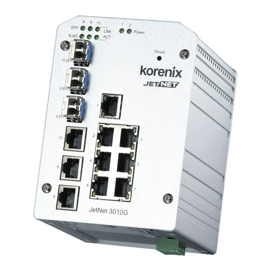
2-2. Front Panel The following diagram shows the front panel of JetNet 3010G, it describes the LEDs, Fast Ethernet and Gigabit Ethernet ports. Figure A. Front Panel of JetNet 3010G 2-3. Bottom View The bottom view of the JetNet3010G Industrial Gigabit Switch consists of one terminal block connector with two DC power inputs. -
Page 8: Wiring The Power Input
Figure B. Bottom view of the JetNet3010G Industrial Gigabit Switch 2-4. Wiring the Power Input The JetNet 3010G supports 2 power inputs with power redundance and polarity auto reverse functions; the typically input power voltage is DC 24V with 12~48V input range. On the bottom side, there is one 4-pin removable terminal block for the redundant power input and the suitable specification of power cable is 12 ~24 AWG. -
Page 9: Wiring The Earth Ground
Note 1: It is a good practice to turn off input and load power, and to unplug power terminal block before making wire connections. Otherwise, your screwdriver blade can inadvertently short your terminal connections to the grounded enclosure. Note 2: The range of the suitable electric wire is from 12 to 24 AWG. Note 3: If the 2 power inputs are connected, JetNet 3010G will be powered from the highest connected voltage. -
Page 10: Led Indicators
2-6. LED Indicators The front panel of JetNet3010G includes 2 Power LEDs, 6 LEDs for Gigabit SFP and RJ-45 ports. Each 10/100Base-TX ports includes 2 LEDs with Green and Yellow color. These LED indicators provide administrators with real-time system status. Table 1 gives descriptions of the function of each LED indicator. -
Page 11: Ethernet Interface Introduction
2-7. Ethernet interface introduction The JetNet 3010G equipped 7 ports 10/100 Fast Ethernet, 3 Gigabit SFP / RJ-45 combo ports. The 10/100Mbps Fast Ethernet ports support auto negotiation and MDI/MDI-X; the Gigabit RJ-45 support 100/1000Mbps for port 8, 9 and port 10 supports 1000Mbps only. -
Page 12: Wiring Cable
SFP port: The SFP port permits standard SFP fiber transceiver, which is provided by Korenix with 3.3v DC power supply. The fiber cable of SFP transceiver will depends on SFP fiber transceiver specification. Please notice that the link connection supports either one of RJ-45 or SFP. -
Page 13: Mounting Installation
3. Mounting Installation 3-1. DIN Rail Mounting The DIN-Rail clip is already attached to the JetNet3010G when packed. If the DIN-Rail clip is not screwed on the JetNet3010G, follow the instructions and the figure below to attach the DIN-Rail clip to the etNet 3010G. Rear Panel of the JetNet3010G 1. -
Page 14: Wall Mounting
2. Lightly push the bottom of the DIN-Rail clip into the track. 3. Check if the DIN-Rail clip is tightly attached to the track. 4. To remove the JetNet3010G from the track, reverse the steps above. Notes: The DIN Rail should compliance with DIN EN50022 standard. Using wrong DIN rail may cause system install unsafe. - Page 15 JetNet3010G onto the wall. 5. To remove the wall mounting plate, reverse the steps above.
-
Page 16: Hardware Installation
4. Hardware Installation The following figure illustrates a typical application of JetNet3010G Industrial Gigabit Switch. This figure illustrates an application of JetNet3010G in factory automation. In the figure, JetNet3010G handle entry level control device, like P.Q., O.K.’S. or serial communication device and provides faster uplink ability with a backbone switch, and also provides gigabit interface for monitoring and H.M.I. - Page 17 the JetNet3010G, refer to Wall Mounting section for wall mounting installation. 3. To place the JetNet3010G on the DIN-Rail track or wall, refer to the Mounting Installation section. 4. Pull the terminal block off the JetNet3010G and wire the power lines. Refer to the Wiring the DC Power Inputs section for how to wire the power inputs.
- Page 18 Type ping 192.168.1.1 command to check the connection. Here we use IP address 192.168.1.1 as an example. Before the testing, be sure your PC host and target device are in the same subnet. 12. Repeat step 10 to make sure that the connection of each device connected to the JetNet3010G is successfully established.
- Page 19 Before you continue, make sure that both PWR1 and PWR2 are successfully connected to power sources. When PWR1 fails, the LED for PWR1 will go out. At that moment, if the ping command is still replying, then it proves that redundant power input function works normally. 15.
-
Page 20: Trouble Shooting
5. Trouble Shooting Make sure you are using the correct DC power suppliers (DC12~ 48 V) or power adapters. Select Ethernet cables with specifications suitable for your applications to set up your systems. Ethernet cables are categorized into unshielded twisted-pair (UTP) and shielded twisted-pair (STP) cables. Category 3, 4, 5 Ethernet cables are suitable for systems with 10 Mbps transmission speed. - Page 21 Port 1~7: 10/100Base-TX Port 8~9 (Combo ): 10/100/1000Base-TX or Gigabit Fiber Port Link Speed (SFP) Port 10 (Combo) : 1000Base-TX or Gigabit Fiber (SFP) Provides Tag Based Class of Service, per port 4 priority queues with 8:4:2:1 W.R.R. rule. Quality of Service Priority ID: High (6,7),Middle (4,5), Low (0,3), Lowest (1,2) Per Fast Ethernet: Link/Activity (Green) Full duplex/Collision (Orange)
-
Page 22: Sfp Fiber Transceiver Order Information
Korenix will keep on certificating and updating the certificated SFP transceivers in Korenix web site and purchase list. You can refer to the web site to get the latest information about SFP transceivers. Note: Poor SFP transceivers may result in poor network performance or can’t meet up claimed distance or temperature. - Page 23 1000Base-XD single-mode SFP transceiver, 50Km, wide operating SFPGXD50-w temperature, -40~85°C SFPGZX70 1000Base-ZX single-mode SFP transceiver, 70Km, -10~70°C SFPGZX70-w 1000Base-ZX single-mode SFP transceiver, 70Km, -40 ℃ - 85°C Some of SFP Transceiver model is not listed on the table, please contact Korenix’s distributor for your inquire.
-
Page 24: Revision History
Revision History Edition Date Modifications V2.0 31-July,2008 New Case design (no curve) 1. Add port link speed table to remind user about the port 10 only support 1000Mbps in RJ-45. 2. Add power installation diagram for UL certificate. Modify chapter 2.7 – Ethernet interface: V2.1 7-Apr,2011 Add explanation of Fiber link first function...
Need help?
Do you have a question about the JetNet 3010G Series and is the answer not in the manual?
Questions and answers