Table of Contents
Advertisement
Quick Links
Advertisement
Table of Contents

Related Manuals for Shining 3D FreeScan Trak Pro2


Summary of Contents for Shining 3D FreeScan Trak Pro2
- Page 1 FreeScan Trak Pro2 V2.1.0.5...
-
Page 2: Table Of Contents
Table of Contents Overview Welcome Getting Started Hardware Introduction Appearance Connection Software Installation Activation Running Upgrade Calibration Preparation Calibration Scan Mode Scan Project Settings Preparation Interface Settings Scan Scan Mesh Partial HD Scanning Scan Global Markers Photogrammetry... - Page 3 Data Editing Alignment FreeProbe Operation Post Processing Mesh Processing Mesh Optimization Measurement Measurement Create Features Align Measurement Tools Save and Export Save Data Data Sharing Third-party Software Contact Us...
-
Page 4: Overview
3. SHINING 3D does not guarantee the applicability of the outcomes of your use of the products, and you are responsible for verifying the quality and functionality of the outcomes. You should check and verify thoroughly that any outcomes meet your requirements before using them, for which you bear full responsibility. -
Page 5: Getting Started
5. The Product Usage Documentation is a guidance for installing, operating, and maintaining the product instead of serving as the quality guaranty for the products. SHINING 3D makes all efforts to ensure the applicability of the Product Usage Documentation, but reserves the right of final interpretation. Images and diagrams in the product documentation are presented to provide convenience to user understanding. -
Page 6: About Software
About Software Here you can learn about software-related information of the device, including software installation, device activation, and other content. How to install software? How to activate the device? How to upgrade the firmware / software? How to run the software and do basic settings? After successfully installing the software and activating the device, you can follow the steps below to operate the device. -
Page 7: Hardware
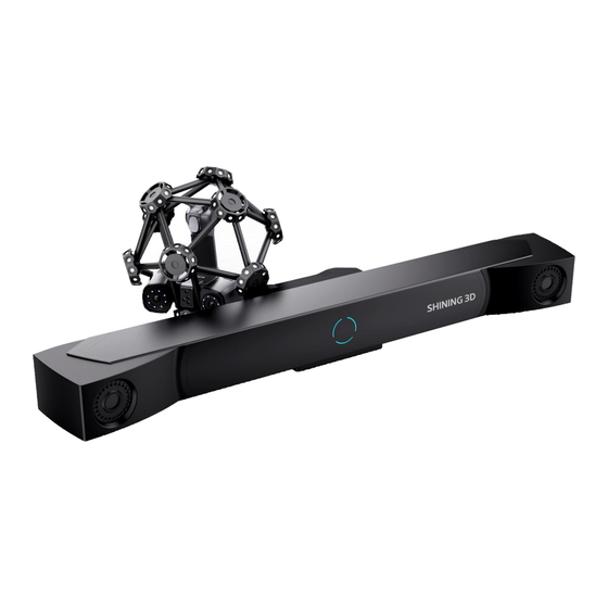
Hardware Introduction Based on the dynamic referencing technology, FreeScan Trak Pro2 is capable of capturing the spatial position of the scanner tip in real time to acquire an accurate and complete 3D data of large or middle-sized objects. The scanner does not require marker placement, thereby simplifying the procedures and reducing the influences on the scanned object to a minimum. - Page 8 Indicator Status Buttons The indicator turns bluish after the device is Press and hold the up button: To turn on / powered on and goes out when the device is off the Local Enlarged View function. on standby. Press and hold the down button: To turn on / off the View Lock function.
- Page 9 Indicator Status Cyan: The device is power on. Red: The device is unconnected to the network. Blue: The device is unconnected to the software. FreeTrak Ⅰ- G1 Green: The device is connected to the network and the software. FreeProbe This instrument can obtain the 3D coordinate of points by touching the surface of an object to achieve different detection targets.
-
Page 10: Connection
Note When the indicator light is blue and the probe is not successfully connected to the software, you can long press the right rhombic button to switch the color of the indicator light to cyan. Buttons Left rhombic button: Short press for power on; press and hold for 5 seconds for power off. In the state of steady green indicator light: ①... - Page 12 Name Description Optical Tracker To be installed on a tripod. Tracker Cable One end for the tracker and the other end for the hub. At the tracker end: One port for power supply, and the other port for network connection. Laser Scanner Scanner Cable One end for the scanner and the other end for the hub.
- Page 13 Front Ports Name Description USB Port To connect the tracker, the scanner and the computer to transmit data. Network Port To connect the computer or the switch to test. Auxillary Power To connect the power adapter (24 V, 3.75 A). It is only available when an Input extended tracker is used.
-
Page 14: Wired Connection
Back Ports Name Description Power Output To power on the extended tracker. Power Output To power on the tracker. Power Output To power on the scanner. Network Port To transmit data of the extended tracker . Network Port To transmit data of the tracker. USB Port To transmit data of the scanner. - Page 15 2. Connect one end of the tracker cable with the tracker. 3. Connect the other end of the tracker cable with the hub. 4. Connect one end of the scanner cable with the scanner.
- Page 16 5. Connect the other end of the scanner cable with the hub. 6. Connect the hub and the power supply with the hub power cable. 7. Connect the hub and the computer with the data cable. 8. Power on the device.
-
Page 17: Software
Software Installation Please install the software before using the scanner. Steps 1. Insert the dongle. 2. Copy the installation file to the PC and double-click to run it. 3. Install the software by following the guidance. Environmental Requirements Recommendation Operating System Windows 11 Professional 22H2 (64-bit) Processor 13th Gen Intel®... - Page 18 If you are using the device for the first time, Please insert the dongle before running the please start the software after installation and software. log in with your SHINING 3D user account to Please run the software after the device indicator activate the device. light is on.
-
Page 19: Device Activation
Register For a new user, create a SHINING 3D user account first. Sign up via the software Click Register and fill in the account information in the registration pop-up. Sign up via the website Click Register a new account in our SHINING 3D User Account website: passport.shining3d.com/login... - Page 20 The activation will be completed automatically after logging in successfully on the networked computer. Offline Activation If the PC cannot be networked, activate the scanner offline. Steps 1. Connect scanner to the computer with no Internet, then export C2SN3D file. 2.
-
Page 21: Running
4. Start to use the device after the successful activation. Note If you fail to activate the device in neither way, please contact your supplier or our technical support. Running If you are using the device for the first time, after logging in and launching the software, it will automatically go to the calibration interface. - Page 22 Interface Caution Check the device connection status by in the upper left corner. If the device is not connected or connected abnormally, check the device connection and then click to reconnect the device.
- Page 23 Reverse Engineering Service: By sending us the scanned project files and specific information, we can assist you with reverse engineering. Option Description Official Open the official website of SHINING 3D to learn about the company's products and Website information. Fackbook Check the Fackbook account of SHINING 3D and get latest information.
- Page 24 General Settings Preview: To preview the scanning effect before scanning when enabled. Global Marker Mode: You can select real-time scanning or still photography before using Trak Mode. For specific scanning operations, please refer to Scan Markers and Photogrammetry. Shape Detection Optimization: To improve the accuracy of sphere diameter at the cost of some details of the scanned data.
-
Page 25: Upgrade
System Diagnose: To check if the computer meets the operating conditions. If all items show , it means that the configuration meets the operation requirements. If not, please resolve the problem according to the prompts in the interface. Click Refresh to diagnose the system again. Support: You can open the user manual, get remote assistance and check contact information of technical support here. -
Page 26: Software Upgrade
When you need to upgrade the firmware of the freeprobe, please first confirm that the probe is connected to the computer hotspot, and then start TrakFirmwareUpdate.exe in the software root directory. Caution If the upgrade fails, please power off the device and reconnect it to try it again. Make sure that the device is powered on during the upgrade;... -
Page 27: Calibration
Caution The software will be closed during upgrading. Please save your projects properly before upgrading. Calibration Preparation You can re-adjust parameters of the device through calibration, which not only ensures the accuracy of the device, but also the scanning quality. Note Calibration is required under the following conditions: The scanner was severely shaken or vibrated during transportation. -
Page 28: Calibration
Caution Do not wipe the calibration board with chemical liquids. Do not put heavy objects or sundries on the calibration board. After using the calibration board, put it in the flannel bag. The calibration board can only be used for the calibration of the device. Keep the calibration board away from corrosives, metals and sharp objects to avoid corrosion or damage. - Page 29 Trak Calibration 1. Stand in the visual field of the tracker with a calibration bar. 2. Move the bar to a correct position and the calibration will start. 3. Change its direction. Note Do not cover or damage the markers on the calibration bar. If the tracker fails to recognize the calibration bar, please follow the guidance and adjust the direction of the bar to make sure it is at a right position in the front view and the top view.
- Page 30 Scanner Calibration 1. Place the calibration board horizontally. 2. Adjust the distance between the scanner and the calibration board according to the height box. 3. Place the scanner in the same direction as shown in the figure and align the center point of the scanner handle with that of the gray circle on the calibration board.
- Page 31 3. Align the three-dimensional graphics and coordinates of the device with the diagrams on the interface one by one, and complete the calibration of all positions. The orientation guide diagram for the current Adjust the position of the device to align the calibration position three-dimensional graphics with the orientation guide diagram.
- Page 32 3. Place the tip of the probe at the specified position according to the interface diagram, and adjust the position of the probe to align with the red indicator diagram multiple times until the entire probe calibration is completed. The navigation bar on the top of the interface will display when the calibration is successful.
-
Page 33: Scan Mode
Scan Mode Trak Mode This mode requires both the tracker and scanner to be online. Once selected, you can quickly obtain scanning data without placing markers on the object in Scan Mesh. It is suitable for medium to large-scale 3D scanning of static / dynamic scenes in manufacturing industries such as aerospace, automotive, rail transportation, energy, etc. -
Page 34: Scan
Scan Project Settings After calibration, please create a project group before scanning, or you can import the existing project group file. Create a Project Group To create a project group, please refer to two ways as follows:... -
Page 35: Project Management
After selecting the scan mode, the project group interface will automatically appear. At this point, select New project group. In the file dialog that appears, enter the name and path for the project group, then click Confirm. All data related to this project group will be saved to the specified path. In the scan interface, click in the right sidebar. -
Page 36: Preparation
Icon Function Description Create a new Click to create a new project. porject Open a project Click to import a project. You can right-click one in the list to rename it. Remove a Click to remove the project from the list, which still exists in the folder and project you can add it in the list by opening it. -
Page 37: Interface
Note When scanning markers in Trak Mode or Laser Mode: Need to place markers on the objects. Place the markers evenly and randomly. Do not use damaged or incomplete markers. Do not use greasy, dusty, or dirty markers. Do not attach the markers to a surface with high curvature. If the device fails to capture markers, it will not emit laser lines. - Page 38 ① Camera Window To display the actual scanning scenarios so that the user can set scanning parameters. ② Project Group and Scan Setting To manage your project group and set scanning parameters. ③ Scan Mode To switch among Scan Mesh, Partial HD Scanning Scan Markers.
-
Page 39: Settings
To edit data after scanning. See more details in Data Editing. ⑧ Keyboard Shortcuts To change the perspectives and move the model by the composition of keys. ⑨ Buttons Click to preview the scanning; click to start scanning; click to pause scanning. ⑩... -
Page 40: High-Speed Mode
Scan Mode You can select Scan Mesh, Partial HD Scanning or Scan Markers. Note When the scanner is in Scan Mesh and there is only one project within the project group, you can adjust the point distance in real time. High-Speed Mode You can improve the scanning speed when it is enabled. - Page 41 Object Select the mode according to the material of the object you are ready to scan. Brightness Drag the slider and adjust the brightness until the scanned data or the markers are clearly visible and complete. Too high brightness may result in much noises in the scanned data. Data Quality Indicator Quality of the scanned data can be displayed by different colors: blue represents a high quality and yellow represents an insufficient scanned data, which needs further scanning.
-
Page 42: Field Of View
View Lock The view in the scanning interface will not vary with the movement of the scanner when the function is enabled. Field of View When the scanner is outside the view field of the tracker, the scanner may not be able to scan data or the quality of the scanned data may be poor. - Page 43 Caution If you move the tracker in a real-world scene, the model position of the tracker in the 3D scene will not change, but the relative position of the scanned object in the 3D scene will change in real-time. Intelligent Resolution After enabling Intelligent Resolution, the software automatically adjusts the mesh resolution based on the curvature of the scanned object.
- Page 44 Laser scan can quickly and accurately acquire 3D data of the scanned object. Featured in contact-free measurement, high sampling rate of data, active emission of scanning light source, low requirements for use, and strong environmental adaptability, laser scan can be used in complex environments, and acquire complete 3D data of large and complex objects into the computer, thereby reconstructing the corresponding 3D model as well as various geometric data concerning the points, lines, surfaces, and solids.
-
Page 45: Scan Operation
Note Click Open global markers file to import the global markers file. Scan Operation Press the scan button on the scanner or click the icons in the interface to switch among Preview, Scan, and Pause (also in this order). Function Icon Description Preview... - Page 46 3. Click to save the data. Add New Global Markers When the markers are not fully scanned in Scan Global Markers, you can choose Add New Global Markers to scan new global markers. Caution Preview scanning is not available when scanning new global markers. Add New Global Markers is only available during mesh scanning in Trak Mode (real-time scanning) and Laser Mode.
-
Page 47: Partial Hd Scanning
Partial HD Scanning Steps 1. Switch to Partial HD Scanning after acquiring the data in the Scan Mesh. Note The light source mode will be automatically switched to parallel lines in Partial HD Scanning. You can switch it to cross lines or single line according to the actual situation. 2. -
Page 48: Laser Mode
Trak Mode 1. Select Trak Mode (still photography) > Scan Markers. 2. (Optional) Click on the right sidebar or press the scan button on the scanner to preview scanning. 3. Click on the right sidebar or press the scan button on the scanner to start scanning. Note During the scanning process, adjust the scanning distance based on the color indications on the scanning interface border:... - Page 49 Note In Laser Mode, after obtaining the global markers, you may notice additional colors outside the global markers. If there is an orange circle outside the markers, it indicates that the quality of the scanned markers is low. If there are no additional colors outside the markers, it means that the quality of the scanned markers is normal.
-
Page 50: Photogrammetry
Photogrammetry Note In the Trak Mode (real-time scanning), after scanning the global markers, you may notice additional colors outside the global markers. If there is an orange circle outside the markers, it indicates that the quality of the scanned markers is low. -
Page 51: Data Editing
Note During the scanning process, adjust the scanning distance based on the color indication box that appears on the scan interface: Blue indicates that the scanning distance is too far. Yellow indicates that the scanning distance is too close. No color indicates that the scanning distance is suitable. 6. - Page 52 Icon Function Description Multi view To view the scanned data from 6 different angles. Cutting plane To create a plane to do quick cutting. See more details in Cutting Plane. Icon Function Description Data editing To edit the selected data. Click it again and you can switch the mode. Edit markers To edit the markers.
- Page 53 Icon Function Description Rectangular To select a rectangular area by holding down ⇧ S h i f t L e f t B u t t o n which will then turn red. Polygon To select a polygonal area by holding down ⇧...
-
Page 54: Right Panel
Caution Once the edit are applied, the data can not be recovered only if you re-load the file. Right Panel Icon Function Description Preview / Scan / To preview the scanned data / To start scan / To stop scan. Pause Global markers To optimize the global markers. -
Page 55: Keyboard Shortcuts
Keyboard Shortcuts Shortcut Function Hold down and move the cursor To rotate the data L e f t B u t t o n Hold down wheel button and move the cursor To move the data To select an area ⇧... - Page 56 1. Click 2. Select the creation method and follow the interface prompts to create a cutting plane. Method Instruction Scan data fitting The plane that the selected data are in will be the cutting plane. Creating straight line The plane that the straight line cuts through will be the cutting plane. Markers The plane that the markers (at least three) are in will be the cutting plane.
- Page 57 Alignment Through alignment, multiple scanned data are combined into a larger mesh, thereby effectively solving the problem of incomplete data collection at one time. Caution When more than two project files with scanned data are present in the project list, these projects can be aligned. Click on the right side of the interface to enter the project alignment interface.
- Page 58 Mode Description Note 1. Choose Auto Feature Alignment. Objects with repeated features, like a round or a ring, or with small size are 2. Select a project to be aligned in the fixed not suitable for this mode. window and the floated window Auto Feature respectively.
- Page 59 2. Press the button on the left rhombic button to turn on. The indicator will turn cyan after powering on. For more button operations, please refer to FreeProbe's appearance. Connection 1. Power on the probe and wait for its indicator to become cyan. 2.
-
Page 60: Battery Specifications
Note If the probe cannot connect successfully, please open Network & Internet > Mobile Hotspot and set the network band to 2.4 GHz. If you are using a desktop computer, you can turn on the mobile hotspot by inserting a wireless network card. If the mobile hotspot cannot be turned on after inserting the wireless network card, please contact technical support. -
Page 61: Post Processing
Cautions Before using the battery and the probe charging case, please read the following safety precautions to prevent dangerous situations such as battery explosions. Caution Do not charge the battery for a long time. Do not reverse the positive (+) and negative (-) terminals. Do not directly solder the battery terminals. - Page 62 Item Description Note Optimization To optimize the data and reduce noises. None: No optimization. A filter with high level may cause the Standard: To optimize data slightly and data to lose some details. preserves data characteristics. Med: To reduce the noise on the surface of the scanned data.
- Page 63 Mesh Optimization After the model data is meshed, the software automatically switches to the Post-processing interface. Alternatively, you can directly click the navigation bar to enter the post-processing interface. Click to select the file for post-processing; or directly drag the file in STL, OBJ, PLY format into the post-processing interface.
- Page 64 Mesh Optimization Item Description Note Simplification To simplify the data by reducing the number The simplification will not be iterated. of triangles. Drag the slider or click the arrows to adjust the ratio. The default is 0. Mesh To optimize the quality of the data. Optimization Drag the slider or click the arrows to adjust the ratio.
- Page 65 Caution After post-processed, the data will not be saved automatically. Please save your data in time. Bottom Panel See more details in Data Editing. Right Panel Icon Function Description Open File To open a file (STL, OBJ, PLY format) for post-processing. Save Your Scan To save the scanned data in a specified format to a specified location.
- Page 66 Additionally, it also supports clicking in the right-side function bar to import models (including third-party 3D models). Note Support opening files in the type of STL, OBJ and PLY. Support dragging the model file into the software interface. Create Features Click and a Create Feature window will pop up on the left.
- Page 67 Point Creation Description Note Method Selected Points 1. Click on the data to select a point. 2. Click Create to create a point. Line-Plane 1. Click the existing feature lines or choose lines in The feature line can't be in Intersection the drop-down list.
- Page 68 Plane Creation Description Note Method 3 Points Fit Click the data or existing feature points to select the point and The three points can't click Create to create a plane. be in a line. Tick the checkbox before the three points and re-select the point.
- Page 69 Precise Alignment Click Move to to align the model center with the input coordinates, and the axis direction is adjusted to match the input rotation angle. The coordinate system displayed on the interface is the global coordinate system, in which the direction of the red line is the positive direction of X-axis, green is the positive direction of Y-axis and blue is the positive direction of Z-axis.
- Page 70 Select a feature surface in the plane drop-down menu, and select an axis in the corresponding constraint drop-down menu of the plane. The arrow on the plane corner indicates the positive direction of the plane, and the selected axis direction will be consistent with the plane direction. Select a feature line in the drop-down menu of the line, and select an axis in the drop-down menu of the line.
-
Page 71: Measurement Tools
Click Align to move the coordinate frame to the center of the object, and the position of the coordinate frame is that the Z axis is parallel to the screen and faces upward, the X axis is perpendicular to the screen and the Y axis is parallel to the screen and faces to the right. -
Page 72: Save And Export
Measurement Description Note Distance Calculate the straight-line distance Click on the surface of the model to pick two between two points on the surface of the points, the calculation will be done model. automatically. Total is the 3D distance. X, Y and Z are the projection of the segment to the respective planes. -
Page 73: Data Sharing
Format Data Type Saved as Application Optimized point Scan.as Data checking cloud (whole scan) Quick export and no need for post-operation Use other software to post- possess the data Mesh Scan.stl 3D printing Reverse engineering Compatible with most post- processing software Mesh Scan.ply Compact size... -
Page 74: Third Party Software
Polyworks Metrology Suite (2023) Contact Us By Email: metrology_support@shining3d.com Support platform: support.shining3d.com SHINING 3D Offices APAC Region & Headquarters SHINING 3D Tech Co., Ltd. Hangzhou, China Phone: +86 571 82999050 Add: No. 1398, Xiangbin Road, Wenyan, Xiaoshan, Hangzhou, Zhejiang, China, 311258... - Page 75 EMEA Region SHINING 3D Technology GmbH. Stuttgart, Germany Phone: +49 711 28444089 Add: Breitwiesenstraße 28, 70565, Stuttgart, Germany Americas Region SHINING 3D Technology Inc. San Leandro, United States Phone: +1 (888) 597-5655 2450 Alvarado St #7, San Leandro, CA 94577...
Need help?
Do you have a question about the FreeScan Trak Pro2 and is the answer not in the manual?
Questions and answers