Table of Contents
Advertisement
Quick Links
Advertisement
Table of Contents

Related Manuals for Shining 3D FreeScan UE Pro


Summary of Contents for Shining 3D FreeScan UE Pro
- Page 1 FreeScan UE Pro User Manual V1.2.2 FreeScan UE Pro_ User Manual _V1.2.2...
- Page 2 Foreword General The Manual introduces the information concerning the installation and the use of FreeScan UE Pro (hereinafter referred to as the “Scanner”). Safety Instructions Signal Meaning Additional information for particular situation. Improper actions or conditions that may damage the product or injury, and consequently void your warranty or service contract or lose the customer data or system data.
- Page 3 information provided herein. FreeScan UE Pro_ User Manual _V1.2.2...
-
Page 4: Table Of Contents
Contents FOREWORD ............................... I HARDWARE ............................1 1.1 I ..............................1 NTRODUCTION 1.2 A ..............................1 PPEARANCE 1.3 C .............................2 ONNECT ABLES SOFTWARE ............................4 2.1 I ..............................4 NTRODUCTION 2.2 O ..........................4 PERATING NVIRONMENT 2.3 I ..............................4 NSTALLMENT 2.4 C ..........................4 ONFIGURE HINING 2.4.1 Register an Account ..........................5 2.4.2 Activate the Scanner ...........................5 2.5 U ................................5... - Page 5 3.5.5 Fill Holes ............................35 3.5.6 Cutting Plane Tool ..........................37 3.6 M ............................37 EASUREMENT 3.6.1 Create Feature ..........................38 3.6.2 Align ..............................39 3.6.3 Measure ............................41 3.7 S ................................43 3.7.1 Save Data ............................43 3.7.2 Share Data ............................45 3.7.3 Third-party Software ........................
-
Page 6: Hardware
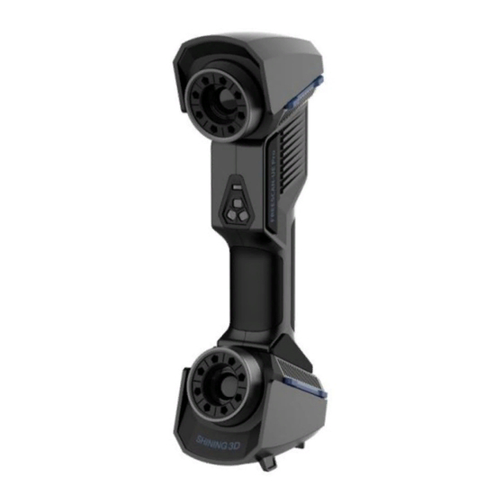
1. Hardware 1.1 Introduction FreeScan UE Pro scanner is a handheld laser 3D scanner independently developed by SHINING 3D, featured in the fast scanning speed, complete data acquisition, light weight, and convenient handholding operation. Besides, the device supports repeatable high-precision operations, without discrimination on the material and color of the objects to be scanned. -
Page 7: Connect Cables
Description Description Menu Camera brightness adjustment Power indicator: Only after the indicator of the Device lights on, the user can operate. Standby Adjustment of the size of display in Preview the software window Scanning Scanning paused Scanning distance indicator: Scanning button ⚫... - Page 8 Attention: Ensure that cables are not loose during the above operations. You are suggested to use fastening tools to prevent the device from being offline. FreeScan UE Pro_ User Manual _V1.2.2...
-
Page 9: Software
2. Software 2.1 Introduction FreeScan software supports UE Pro scanners. With user-friendly software interface, full process scanning guidance, simplified software settings, you can operate the Scanner easily. 2.2 Operating Environment Recommended operating environment of the software: ⚫ Operating system: Windows 10 Pro. and above (64-bit only) ⚫... -
Page 10: Register An Account
2.4.1 Register an Account Register an account if you do not have a Shining account or access to the software interface for the first time. To register an account, ensure your PC is networked. Step 1 Click Register. Step 2 Enter account information and user information. Step 3 Select Read and agree to Privacy Policy (Mandatory) and Read and agree our Marketing and Promotion Agreement (Optional). -
Page 11: Upgrade Software
power cuts. ⚫ Back up the original firmware so as to retrieve it in case of upgrade failure or in case that the user finds the new version unsatisfactory. ⚫ Download the new firmware files to the local computer where the software has been installed. Upgrading process: The software will automatically detect the firmware. - Page 12 Click “Download Now”. The software will automatically download the installation package in the background. Do not close the software during the download. When the download is completed, a window automatically pops up for users to decide whether the new version shall be installed immediately. Click “Yes” to start installing the new updates.
-
Page 13: Operation
3. Operation This Chapter mainly explains how to perform scanning, editing, and setting to the models through the software. Double-click to enter the operational interface. 3.1 Workflow If it is the first time you operate the system, refer to the following process. Figure 3-1 Operation flowchart 3.2 Calibration Through calibration, the device parameters are recalculated, which not only ensures the accuracy of the... -
Page 14: Introduction To The Calibration Interface
Accuracy of calibration directly affects the scanning accuracy. Re-calibration is required Under the following conditions: - When the scanner is used for the first time, or when it is reused after being laid idle for a long period of time (1-2 weeks). -... -
Page 15: Create A Project
select “Calibration” on the navigation bar to switch to the calibration interface. Follow the steps provided by the calibration wizard on the right side of the interface. Step 1 Place the calibration board horizontally. Step 2 Align the center point of the Device’s handle with the center point of the gray circle on the calibration board. -
Page 16: Scan
Step 4 Click “Apply”. 3.4 Scan Laser scanners can quickly and accurately obtain 3-dimensional data of objects scanned. Laser scanners are featured in non-contact measurement, high data sampling rate, active emission of scanning lights and strong environmental adaptability. These devices can be used in the complex environments and spaces for scanning, and directly and completely acquire the 3D data of physical objects with various sizes. - Page 17 Introduction to the scanning interface: Introduction to the scanning interface FreeScan UE Pro_ User Manual _V1.2.2...
- Page 18 Item Description It is used to preview the actual scene during scanning. Parameters can be Camera windows adjusted accurately through the camera window. Project group and scan For project group settings, see 3.4.6 Project Management. For scan setting settings, set scan mode and parameters. Through scanning settings, the scanning mode and parameters can be set.
-
Page 19: Preparation
Project import, manual alignment, data deleting, and data saving can be Functions performed. For related content, please refer to 3.4.6 Project Management and 3.4.8 Alignment. Mesh See 3.4.9 Mesh. 3.4.1 Preparation To obtain better scanning effects, please pay attention to the following details when scanning: ⚫... -
Page 20: Preview
Error 1- artificial grouping of markers Error 2- Attach markers only on one line ⚫ When scanning a model prone to being deformed, make sure deformation does not occur. 3.4.2 Preview To acquire better scanning effects through previewing and adjusting the parameters. Click on the right side of the interface or press the Scan button on the Device to enter the preview mode. -
Page 21: Parameter Setting
3.4.3 Parameter Setting Scanning parameters can be set during preview or scanning, including setting of scanning distance, light source modes, scanning objects, brightness. ⚫ Adjustment of the scanning distance: There is a bar on the left side of the preview interface, displaying the scanning distance. -
Page 22: Point Cloud Scanning
the brightness on the camera window until the data and markers are clearly visible. Attention: If the brightness is too high, a large amount of noise can occur to the scanned data. The parameters are inappropriately adjusted. Please adjust the scanning distance and/or Parameters are appropriately adjusted. -
Page 23: Partial Hd Scanning
Step 2 After scanning, click on the right to generate point clouds. After the point clouds data is generated, the system will automatically optimize and generate point clouds. This function can also be used under offline mode. Point clouds not generated Point clouds generated (scanning data optimized) Step 3 Click to save the scanned data in .asc or .p3 format. -
Page 24: Scanning Global Markers
2. Press and hold Shift + left button of the mouse to select an area on the object to be scanned. The selected area will be displayed in red. Step 4 Set point distance. 1. Click or drag the slider located under Partial HD Scanning or use the up/down arrows on the right to adjust the point distance, ranging from 0.03mm to 0.4mm. -
Page 25: Photogrammetry
Step 1 Select the global markers scanning mode. Step 2 Click located on the right-hand side of the interface or press the Scan button on the Device to enter preview mode. The scanning parameters are adjustable. Step 3 Start scanning. Click on the right-hand side or press the Scan button on the Device to start collecting markers. -
Page 26: Project Management
3.4.8 Project Management Import a Project The system allows to create a project instantly by importing the existing scanned data into it. In the project management window, click “Open project group”; or in the scanning interface, click on the right; the project file window will pop up. Then select a project file, click “Open” at the bottom right to import the project. -
Page 27: Edit Data
Open project After clicking, a project file will be imported. Select a project in the project list and right-click on it, select “Rename” to rename the project. Remove project After clicking, the project will be removed from the list. This operation does not delete the project. - Page 28 ⚫ Alternatively, select the perspective selecting button, click located at the bottom of the interface, and select different previews under various perspectives. Introduction to perspective adjustment Icon Description Front view, viewing the object to be scanned from the front perspective. Top view, viewing the object to be scanned from the top perspective.
- Page 29 Step 4 Click “Create Plane” to generate the cutting plane. Step 5 Drag the blue ball to adjust the X, Y, Z axis or translation increment to determine the direction and angle of the plane. ⚫ Delete a plane: After clicking, the scanned data below the plane will be deleted. ⚫...
- Page 30 Icons Name Description Point cloud Edit Edit the selected data area in Point cloud Edit mode. Markers Edit Click Point cloud Edit again to switch to Mark Edit. Select the data area and the mark points in this area will in red. The red mark points can be deleted at this time.
-
Page 31: Align
Connected Domain To enable domain connecting function, selecting a patch of data and click this button, model area associated with such data will be automatically selected. Invert After clicking, areas other than the selected editing areas will be selected. Delete selected data After clicking, the selected editing area will be deleted. - Page 32 individual scanned area may overlap. Therefore, alignment is done to obtain identical surface features based on the repeatedly scanned areas, connecting such point cloud data obtained through multiple scans into one complete set of data. Through alignment, multiple scan data are combined into a whole set of point cloud data, thereby effectively solving the problem of incomplete data collection.
- Page 33 Feature Alignment When the scanned point cloud files share common features, feature alignment can be chosen, which is the most effective way to solve the alignment problem. This method can adjust the manual alignment to minimize the error between the model and the original data. Select “By Feature”...
-
Page 34: Mesh
Press Ctrl + Z or ESC to undo the selected points in sequential order. Markers Alignment If the currently selected project is a Markers project, the markers can be aligned. It is necessary to ensure that the number of shared markers in the two projects is not less than 3. Otherwise, the alignment will fail. The software will automatically align according to the markers. - Page 35 Use recommended parameters: Turn on the function, software helps you to optimize a specific model. To customize parameters, turn off the function. Filter: Optimize data. Filter Low Filter Med Remove small floating parts: Remove small floating parts on the model. Remove spikes: Remove spike-like data on the image edge.
-
Page 36: Post-Processing
Fill small hole: For objects with tiny holes (larger than 10 mm), use the function to fill tiny hole to make the scanned image look better. For objects with holes (smaller than 10 mm), you are not recommended to use the function or you can set the function parameter value to a smaller one. -
Page 37: Simplification
Shift+ Left Button of the mouse: Select the redundant part of data, and the selected data will be displayed in red. Ctrl+ Left Button of the mouse: Deselect part of the selected data. Icon Name Description Select visible When selecting the model processing area, only one side is selected, that is, visible data is selected. -
Page 38: Mesh Optimization
Multiple operations on “Simplification”, the result will not be added. It will always operate on the original data. Before simplification After simplification 3.5.2 Mesh Optimization Mesh optimization can optimize the quality of the data. There are 3 ratio options of mesh optimization. Processing time will be different. -
Page 39: Smooth
Click Apply to optimize data, preview the result of current setting. Click Confirm to apply the “Mesh Optimization” setting. Click Cancel to quit and go back to the original data. Multiple operations on “Mesh Optimization”, the result will not be added. It will always operate on the original data. -
Page 40: Remove Small Floating Parts
3.5.4 Remove Small Floating Parts Remove small floating parts in the scan data. 0 means no operation, 100 is the maximum. The maximum value is the square of the diagonal length of the floating part/10, MAX=(L/10)². Diagram of removing floating parts shows as below: Original data Remove floating part-10 Remove floating part-50... - Page 41 Auto hole filling Choose Curvature, Tangent or Flat before filling hole. ⚫ FLAT calculates the solution for the hole filling considering the point position on the boundary. ⚫ TANGENT calculates the solution considering the point position and the normal of the last row of triangles forming the boundary.
-
Page 42: Cutting Plane Tool
Manual hole filling Click the edge of the hole to fill it. Click , according to the order of filling holes, from the last hole to cancel hole filling. Ctrl + Z can also cancel hole filling. Click Confirm to apply current setting and exit the manual hole filling. Click Cancel to quit and go back to the original data. -
Page 43: Create Feature
3.6.1 Create Feature Click the feature button to display the menu, click again or “Close” to close the menu. Feature menu Display of Features Click on the corresponding icon to create points, lines, planes. Then select the creation method and follow the instructions, click “Create” to generate, or “Close” to cancel and close the window. -
Page 44: Align
Feature creation failed! Error code 1: the planes are parallel. ⚫ The plane is generated by 3 points not co-linear. ⚫ Click on the data to select one point or click on a previous created feature point. 3 Points Fit —... - Page 45 Exact movement Exact movement menu Enter the value in mm and degrees, click Apply to match the data origin to the input coordinate and orientation. The arrows represent the global coordinate system, Red=X+, Green=Y+, Blue=Z+. Click Reset to cancel the transformation to original position. Click OK to confirm the transformation.
-
Page 46: Measure
3-2-1 Movement menu ⚫ Select a Plane in the drop-down menu, match it to the first axis in the Method drop-down. The arrows on the corners of the plane represent the plane positive direction. The normal vector of the plane will match the axis direction. - Page 47 Distance menu Total is the 3D distance, X, Y and Z are the projection of the segment to the respective planes. SURFACE AREA Press Shift+ LMB to select an area, press ctrl + LMB to unselect. Ctrl + A to select all. Click Calculate to display the Area value of the selected data in mm^2 Redo the selection and click calculate again to update.
-
Page 48: Save
Volume menu File not watertight alert Enter/exit the measurement interface Click the “Measure” button to enter the measurement interface and display the measurement menu, click the button again to exit the measurement interface. 3.7 Save 3.7.1 Save Data Save data. Enter the file name and click the save button. - Page 49 First select the saving path, enter the file name, and select the file type. The files for non-texture scanning is to be saved as stl by default and, files for texture scanning is saved as obj by default. At least one type is required to be selected.
-
Page 50: Share Data
3.7.3 Third-party Software Five third-party software, including Geomagic Control X, Verisurf, Geomagic Design X, Geomagic Essentials and Solid Edge SHINING 3D Edition are included. Users can import scanned mesh data into the third-party software with one click. Geomagic Control X Export data to Geomagic Control X Mainly used for 3D inspection. -
Page 51: Preview Model
Export data to Solid Edge SHINING 3D Edition Mainly used for reverse design of mesh data. Solid Edge SHINING 3D Edition is a 3D CAD software. If Solid Edge SHINING 3D Edition has been installed, clicking this button will open the Solid Edge SHINING 3D Edition and import the mesh stl data into Solid Edge SHINING 3D Edition. -
Page 52: Other Operations
3.8 Other Operations Icons Functions Descriptions Official Website Open the official website of Shining 3D to learn about the company’s products and information. Facebook Enter Shining 3D’s facebook to view product introduction and other operations. Support Platform Enter Shining 3D’s support platform to view product... - Page 53 information or scanned data, and will not be accessible to any third party. The User Experience Enhancement Program will continuously keep you informed with the newest software update information, to assure you get free software updates and enjoy the latest improvements based on your collective feedback.
-
Page 54: Contact Us
Contact Us By Email: metrology_support@shining3d.com Support platform: support.shining3d.com Shining 3D Offices APAC Region & Headquarters SHINING 3D Tech Co., Ltd. Hangzhou, China Phone: +86 571 82999050 Add: No. 1398, Xiangbin Road, Wenyan, Xiaoshan, Hangzhou, Zhejiang, China, 311258 EMEA Region SHINING 3D Technology GmbH.
Need help?
Do you have a question about the FreeScan UE Pro and is the answer not in the manual?
Questions and answers