Table of Contents
Advertisement
Quick Links
Advertisement
Table of Contents

Related Manuals for Shining 3D FreeScan UE


Summary of Contents for Shining 3D FreeScan UE
- Page 1 FreeScan UE User Manual V1.2.0.0 FreeScan UE_ User Manual _V1.2.0.0...
- Page 2 Foreword General The Manual introduces the information concerning the installation and use of FreeScan UE (hereinafter referred to as the “Scanner”). Safety Instructions Signal Meaning Additional information for particular situation. Improper actions or conditions that may damage the product or injury, and consequently void your warranty or service contract or lose the customer data or system data.
- Page 3 Company shall not be held responsible for any damages and/or losses caused by negligence, environmental factors, or improper maintenance and use, or any other factors other than due to the quality of the Product. ⚫ Disputes arising from the Manual and related Products thereof shall be governed by the laws of the People’s Republic of China.
-
Page 4: Table Of Contents
Contents FOREWORD ............................... I HARDWARE ............................1 1.1 I ..............................1 NTRODUCTION 1.2 A ..............................1 PPEARANCE 1.3 C .............................2 ONNECT ABLES SOFTWARE ............................4 2.1 I ..............................4 NTRODUCTION 2.2 O ..........................4 PERATING NVIRONMENT 2.3 I ............................4 NSTALL OFTWARE 2.4 U ................................5 PGRADE 2.4.1 Upgrade Firmware..........................5 2.4.2 Upgrade Software ..........................6 3. - Page 5 3.7 S ................................40 3.7.1 Save Data ............................40 3.7.2 Share Data ............................42 3.7.3 Third-party Software ........................42 3.7.4 Preview Model ..........................44 3.8 O ............................44 THER PERATIONS CONTACT US ............................46 FreeScan UE_ User Manual _V1.2.0.0...
-
Page 6: Hardware
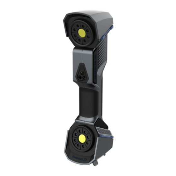
1. Hardware 1.1 Introduction FreeScan UE scanner is a handheld laser 3D scanner independently developed by Shining 3D, featured in the fast scanning speed, complete data acquisition, light weight, and convenient handholding operation. Besides, the device supports repeatable high-precision operations, without discrimination on the material and color of the objects to be scanned. -
Page 7: Connect Cables
Point cloud indicator: Only after the indicator of the Device lights up can the user enable the software for operations. When the light is on, the point cloud indicator lights up around the menu button. Adjustment of the size of display in the software window Standby Pre-scan... - Page 8 Attention: Ensure that cables are not loose during the above operations. You are suggested to use fastening tools to prevent the device from being offline. FreeScan UE_ User Manual _V1.2.0.0...
-
Page 9: Software
Step 2 Double-click to run the installation package. The “Installer Language” window pops up. Step 3 Select the desired language and click “OK”. Step 4 After “FreeScan UE XXXX” Installation Wizard pops up, click “Next”. Step 5 On the License interface, click “I accept”. -
Page 10: Upgrade
The software may work abnormally due to conflicts in authorizations. Step 8 Click “Finish” to complete the installation. Notes: Check “Run FreeScan UE 1.2.X.X”, then click on “Finish”. The software will run automatically after installation is completed. 2.4 Upgrade 2.4.1 Upgrade Firmware... -
Page 11: Upgrade Software
Notes: ⚫ After upgrade is confirmed, the software will be shut off automatically. ⚫ The upgrade takes about 5 minutes. 2.4.2 Upgrade Software Software upgrading is conducted to better satisfy the users by providing patches they can download to their system to optimize its performance and/or append new features. - Page 12 FreeScan UE_ User Manual _V1.2.0.0...
-
Page 13: Operation
This Chapter mainly explains how to perform scanning, cutting, and setting to the models through the software. Double-click to enter the operational interface of FreeScan UE. 3.1 Workflow If it is the first time you operate the system, refer to the following process. -
Page 14: Introduction To The Calibration Interface
- The scanner was severely shaken or shocked during transportation. - Severe accuracy reduction, such as frequent errors in alignment, is observed during the scanning. - Incomplete data is acquired during the scanning or serious deterioration of the quality of scanned data. -
Page 15: Quick Calibration
3.2.3 Quick Calibration The system directly enters the calibration interface when it is used for the first time. Alternatively, users can select “Calibration” located on the navigation bar to switch to the calibration interface. Follow the steps provided by the calibration wizard on the right side of the interface. Step 1 Place the calibration board horizontally. -
Page 16: Scan
models that require high precision, such as stamps, it is recommended to select high resolution. On the other hand, larger models without high requirements on precision, such as doors of automobiles, are recommended to be scanned under lower resolutions. ⚫ Point distance: Refers to the distance between points in the point cloud. - Page 17 Introduction to the scanning interface: Introduction to the scanning interface Item Description Camera window It is used to preview the actual scene during scanning. Parameters can be adjusted accurately through the camera window. Scan Setting Through scanning settings, the scanning mode and parameters can be set. ⚫...
- Page 18 Default is scan point cloud. You can choose scan point cloud, scan markers or open global markers file. ◆ Scan point cloud: Acquire the data as point cloud. It could be switched to scan point cloud mode after scanning markers. It is also feasible to import the generated global marker file and then scan the point cloud.
-
Page 19: Preparation
3.4.1 Preparation In order to obtain ideal scanning effects, please pay attention to the following details when scanning: ⚫ Markers shall be attached to models to be scanned. If the Device fails to scan markers, it will not emit laser rays. -... -
Page 20: Parameter Setting
⚫ The pre-scan mode can be switched on after operations such as creating a new project, importing a project, pausing scanning, and finishing scanning. Click or press the Scan button on the Device again to exit the pre-scan mode and start scanning. 3.4.3 Parameter Setting Scanning parameters can be set during pre-scan or scanning, including setting of scanning distance, light source modes, scanning objects, brightness and data settings. -
Page 21: Point Cloud Scanning
Table 4 The parameters are inappropriately adjusted. Please Parameters are appropriately adjust the scanning distance and/or scanning brightness adjusted. ⚫ Data setting: When adjusted to high quality , less noise is present in the data; and if adjusted to high completeness , black objects that are difficult to scan can be scanned. -
Page 22: Scanning Global Markers
Step 2 After scanning, click on the right to generate a point cloud. After the point cloud is generated, the system will automatically optimize and generate a point cloud. This function can also be used under offline mode. Point clouds not generated Point clouds generated (scanning data optimized) Step 3 Click to save the scanned data in .asc or .p3 format. -
Page 23: Project Management
the “New Global markers” option is not checked, new global markers identified in the scanning will not be added to the scanned data. 3.4.6 Project Management Import a Project The system allows to create a project instantly by importing the existing scanned data into it. In the project management window, click “Open multiple projects”;... -
Page 24: Edit Data
become current project. Open a project After clicking, a project file will be imported. Select a project in the project list and right-click on it, select “Rename” to rename the project. Remove a project After clicking, the project will be removed from the list. This operation does not delete the project. - Page 25 Adjust View ⚫ Hold down the left button and move the mouse to rotate the model. ⚫ Alternatively, select the perspective selecting button, click located at the bottom of the interface, and select different previews under various perspectives. Introduction to perspective adjustment Icon Description Front view, viewing the object to be scanned from the front perspective.
- Page 26 ⚫ Create a straight line: Draw a straight line on the object to be scanned, and the plane formed by such a straight line is deemed as a cutting plane. ⚫ Markers: At least 3 markers shall be chosen and the plane formed by these 3 or more markers shall be deemed as the cutting plane.
- Page 27 Step 6 Click “Apply”. No data below the cutting plane will be collected. Edit Model Users can select data to edit the model at their own discretion. Introduction to editing icons Icons Name Description Rectangular After clicking, a rectangular area can be selected for editing. Press and hold the left button of the mouse to select an area to be edited.
- Page 28 Lasso After clicking, hold down both “Shift and Left Mouse Button” and a blue circle will appear. At this time, roll the mouse wheel will zoom in and out of the blue circle. Move the blue circle to select the area to be edited. The selected area will be displayed in red.
-
Page 29: Align
Shortcut Keys The objects to be scanned can be edited through shortcut keys. Shortcut keys Instruction Hold down the left mouse button and move the cursor Rotate the model Hold down the middle mouse button and move the cursor Translate the model Roll the mouse wheel up and down Zoom in and zoom out the model Space bar... - Page 30 Notes: If there is a project that has not generated a point cloud, click “Align” and the following prompt box will pop up. If “Continue” is clicked, the point cloud will be automatically generated and then aligned; if “Cancel” is clicked, alignment interface will appear and the project that has not generated point cloud will not be displayed on the alignment interface.
- Page 31 Manual Alignment Manual alignment refers to obtaining the initial position of the point cloud through three points. For large-scale point clouds, the less precise manual alignment method can be selected. The best matches of the selected points are calculated and, alignment is realized through the best fitting of all the points from the floating viewport to the fixed viewport.
-
Page 32: Mesh
Through the toolbar on the left, you can simplify, optimize, remove small floating parts, remove spike and fill marker hole. Use recommended parameters: To get FreeScan UE help you optimize a specific model, enable the function. To customize parameters, disable the function. - Page 33 Remove small floating parts: Remove small floating parts on the model. Remove spikes: Remove spike-like data on the image edge. triangles: Set max. plate number to get mesh model’s triangle plate number is within configured plate number. Fill small hole: For objects with tiny holes (larger than 10 mm), use the function to fill tiny hole to make the scanned image look better.
-
Page 34: Post-Processing
Marker hole filling: Without markers fill With markers fill 3.5 Post-processing After the model data is encapsulated, the software automatically switches to the post-processing interface. Alternatively, users can directly click on the navigation bar to enter the post-processing interface and import data. -
Page 35: Mesh Optimization
Simplification menu Click Apply to simplify data, preview the result of current setting. Click Confirm to apply the “Simplification” setting. Click Cancel to quit, and go back to the original data. Multiple operations on “Simplification”, the result will not be added. It will always operate on the original data. -
Page 36: Smooth
Original Mesh optimization 10 Mesh optimization 50 Mesh optimization 100 Click Apply to optimize data, preview the result of current setting. Click Confirm to apply the “Mesh Optimization” setting. Click Cancel to quit, and go back to the original data. Multiple operations on “Mesh Optimization”, the result will not be added. -
Page 37: Remove Small Floating Parts
Original Smooth 10 Smooth 50 Smooth 100 Click Apply to smooth data, preview the result of current setting. Click Confirm to apply the “Smooth” setting. Click Cancel to quit, and go back to the original data. Multiple operations on “Smooth”, the result will not be added. It will always operate on the original data. 3.5.4 Remove Small Floating Parts Remove small floating parts in the scan data. -
Page 38: Fill Holes
Remove floating part-10 Remove floating part-50 Remove floating part-100 Click Apply to remove floating part, preview the result of current settings. Click Confirm to apply the “remove floating part” setting. Click Cancel to quit, and go back to the original data. Multiple operations on “Remove floating part”, the result will not be added. -
Page 39: Measurement
Click Apply to auto fill hole, preview the result of current setting. Click Confirm to apply the “Auto hole filling” setting. Click Cancel to quit, and go back to the original data. Manual Hole Filling The hole edges are displayed green, and get red after picking. The number of the holes and the number of holes filled will be displayed on the interface. -
Page 40: Create Feature
3.6.1 Create Feature Click the feature button to display the menu, click again to close the menu. Feature menu Display of Features Click on the corresponding icon to create points, lines, planes. Then select the creation method and follow the instructions, click “Create” to generate, or “Close” to cancel and close the window. -
Page 41: Align
planes are parallel. ⚫ The plane is generated by 3 points not co-linear. ⚫ Click on the data to select one point or click on a previous created feature point. 3 Points Fit — ⚫ In the Choice list select one of the points to reselect it. - Page 42 Enter the value in mm and degrees, click Apply to match the data origin to the input coordinate and orientation. The arrows represent the global coordinate system, Red=X+, Green=Y+, Blue=Z+. Click Reset to cancel the transformation to original position. Click OK to confirm the transformation. Tips: ⚫...
-
Page 43: Measure
⚫ Select a Plane in the drop-down menu, match it to the first axis in the Method drop-down. The arrows on the corners of the plane represent the plane positive direction. The normal vector of the plane will match the axis direction. - Page 44 Distance menu Total is the 3D distance, X, Y and Z are the projection of the segment to the respective planes. SURFACE AREA Press Shift+ LMB to select an area, press ctrl + LMB to unselect. Ctrl + A to select all. Click Calculate to display the Area value of the selected data in mm^2 Redo the selection and click calculate again to update.
-
Page 45: Save
File not watertight alert Enter/exit the measurement interface Click the “Measure” button to enter the measurement interface and display the measurement menu, click the button again to exit the measurement interface. 3.7 Save 3.7.1 Save Data Save data. Enter the file name and click the save button. Export data FreeScan UE_ User Manual _V1.2.0.0... - Page 46 First select the saving path, enter the file name, and select the file type. The files for non-texture scanning is to be saved as stl by default and, files for texture scanning is saved as obj by default. At least one type is required to be selected.
-
Page 47: Share Data
3.7.2 Share Data Share data. Click the Share button to upload the encapsulated data to Sketchfab. Sketchfab Uploading Window The scanned model can be shared to the Sketchfab website, where the title, username and password are required to be provided. You can register an account on the Sketchfab (http://sketchfab.com) to view the shared models. - Page 48 Geomagic Control X Export data to Geomagic Control X Mainly used for reverse design of mesh data. If the GeomagicControl X software has been installed, clicking this button will open the GeomagicControl X software and import the mesh data. Verisurf Export data to Verisurf If the Design with Verisurf software has been installed, clicking this button will open the Design with Verisurf and import the encapsulated stl data into Design with Verisurf.
-
Page 49: Preview Model
When importing Obj texture files, ensure that mtl and jpg sharing the same file name are under the same directory as obj. 3.8 Other Operations Table 8 Icons Functions Descriptions Official website Open the official website of Shining 3D to learn about the company’s products and information. FreeScan UE_ User Manual _V1.2.0.0... - Page 50 WeChat account Enter Shining 3D’s public WeChat account to view product introduction and their operations. Advanced mode After checking this option, the point distance can be selected as 0.05 when creating a new project. User feedback You can communicate any of your advice or questions with us through “User Feedback”...
-
Page 51: Contact Us
By Email: metrology_support@shining3d.com By Skype: shining3d_sales Support platform: support.shining3d.com Shining 3D Offices APAC Region & Headquarters SHINING 3D Tech Co., Ltd. Hangzhou, China Phone: +86 571 82999050 Add: No. 1398, Xiangbin Road, Wenyan, Xiaoshan, Hangzhou, Zhejiang, China, 311258 EMEA Region SHINING 3D Technology GmbH.
Need help?
Do you have a question about the FreeScan UE and is the answer not in the manual?
Questions and answers