Table of Contents
Advertisement
Quick Links
Advertisement
Table of Contents

Related Manuals for Shining 3D FreeScan Combo


Summary of Contents for Shining 3D FreeScan Combo
- Page 1 V2.0.1.5...
-
Page 2: Table Of Contents
Table of Contents Overview Welcome Device Installation Activation Upgrade Interface Quick guide Quick calibration Scan Workflow Preparation Scan mode Project and project group Project setting Setting Scanning Data editing Functions Alignment Post Processing Mesh editing Mesh optimization Measurement Tools Create features Align Measurement Save... - Page 3 Save data Date Sharing Third-party Software Contact us...
-
Page 4: Welcome
Terms of use SHINING 3D Tech Co., Ltd. (hereinafter referred to as "the Company") owns complete intellectual property rights for the contents of this document and, without the written consent of the Company, it is not allowed to copy, transmit, publish, reedit, compile or translate any contents of this document for any purpose or in any form. -
Page 5: Device
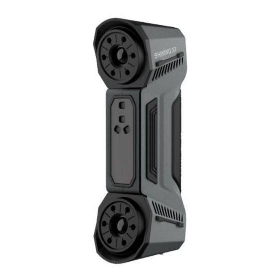
Device FreeScan Combo is a handheld laser 3D scanner independently developed by SHINING 3D. The scannner supports the laser mode and the IR mode. The laser mode is mainly used in industry scanning; the IR mode is mainly used in portrait scanning and object scanning. -
Page 6: Connect Cables
Name Description Scanning distance Only after the power indicator lights on, the scanner can be indicator/Power indicator operated. Scanning distance indicator: Red: too close Yellow: relatively close Green: suitable distance Greenish-blue: relatively far Blue: too far Scanning Button Click: Preview/Start Scan/Pause Scan. Double-click: call out the menu, and at this time the scanning button becomes the confirmation button. - Page 7 Caution Make sure you are using the correct power adapter (12 V / 5 A). Steps 1. Connect the aviation cable (4) to the power port (1) and the USB port (2). 2. Connect the power cord (6) to the power adapter (7). 3.
-
Page 8: Installation
Note To prevent accidental dropping of the scanner from the hand, it is advisable to attach a wrist strap at the rear of the scanner. You can wear the strap while using the scanner. Note Please ensure that the external adapter for the computer is plugged in. It is recommended to use hardware configuration with dual-channel memory. -
Page 9: Graphics Card
Steps 1. Insert the flash drive. 2. Copy the installation file to the PC and run it. 3. Install the software by following the installation wizard. 4. Click Finish and run the software. Note Administrator rights are required for the software installation. The initial installation environment may take a long time, please wait patiently. -
Page 10: Activation
Fill in correct user information for better service. Login Log in Shining 3D User Account from the pop-up window when launching FreeScan. If your computer failed to connect to the network: Check the network connection and click Refresh to reconnect to the network. It will jump back to the login interface after successfully connecting to the network. -
Page 11: Device Activation
Network Not Available Passport Device activation Online activation The activation will be completed automatically after logging in successfully on the networked computer. Offline activation If the PC cannot be networked, activate the scanner offline. 1. Export C2SN3D file. a. Prepare a USB flash drive or portable hard disk. b. - Page 12 2. Upload C2SN3D file. a. Enter https://passport.shining3d.com/login on the networked computer. Then log in or register a new account. b. Click OFFLINE ACTIVATION. c. Upload the C2SN3D file. 3. Export the SN3D2C file corresponding to your scanner account to your USB flash drive. 4.
-
Page 13: Upgrade
Note Please contact the supplier or technical support if none of the above methods can activate your device. Upgrade When a new version of the software is released or a higher firmware version is available, you will be prompted when launching the software. Firmware upgrade Update the firmware for better performance, stability or bug fixing. -
Page 14: Interface
Click Download Now will download the installation package in the background. Do not close the software during the download process. When the download is completed, a window automatically pops up for users to decide whether the new version shall be installed immediately. Click Yes to start installing. - Page 15 IR mode ①Navigation bar Device: Display the device name and status: online / offline. Click to reconnect when the scanner is offline.
- Page 16 Official website:Open the official website of Shining 3D to learn about the company’s products and information. Facebook:Enter Shining 3D’s Facebook to view product introduction and other operations. Support platform: Enter Shining 3D’s support platform to view product introduction and other operations.
- Page 17 Preview:You can preview the scanning effect before the actual scanning when enabling the function. Shape detection optimization:It can improve the accuracy of sphere diameter but may affect some details of the scanned data. Scanner tone:Adjust the volume of the scanner's beep sound. Laser scan settings Scanning distance indication method:There are two methods to indicate the scanning distance.
-
Page 18: Quick Guide
③Scanning Settings Camera windows: To preview the actual scene during scanning. Parameters can be adjusted accurately through the camera window. Project group: To manage projects and the project group. For more, see Project and Project Group. Scanning parameters: To set scanning parameters. For more, see Setting. ④Memory/CPU/GPU Remaining memory CPU usage: If the running program occupies a large proportion, it is recommended to close other software. -
Page 19: Quick Calibration
If you are using the scanner for the first time, Create a project please perform the calibration first. Once the calibration is completed, the software will automatically skip this step when you enter it again. Calibrate Step 3 Step 4 After creating the project, you can set the scan Scan the object and obtain the data. - Page 20 Caution Start to calibrate when the temperature of the device get high enough(35℃). The calibration board is matched to the device. Calibrating with an mismatched calibration board will lead to inaccuracy or fail to get good scanned data. Always make sure that both sides of the calibration board are clean and free of scratches. Do not place heavy objects or sundries on the calibration board.
-
Page 21: Scan
5. Move the device slowly and adjust the distance between the scanner and the calibration board according to the height indicating box. 6. Keep moving until all height boxes turn green. 7. Check the calibration result. Note Please calibrate again if the calibration fails. During the calibration process, please ensure that there are not a large number of markers around the calibration board, so as not to affect the calibration accuracy. -
Page 22: Workflow
Workflow There are two different workflows: Basic workflow, Global marker workflow. The basic scanning mode can meet most of general scanning needs, and the global markers scanning mode can be used when you need to scan for higher accuracy or scan thin-walled parts. - Page 23 Basic scanning workflow...
- Page 24 Global markers scanning workflow...
-
Page 25: Preparation
Preparation Make some preparations when scanning different objects. Marker Markers shall be attached to models. If the device fails to catch markers, it will not emit laser lines in the laser scan mode. Attach the markers evenly and randomly. Four markers are required for the alignment at communal areas. Ensure that the device’s camera can scan at least 4 markers within the normal scanning range. -
Page 26: Scan Mode
1. 3mm markers are the minimum markers identified in the laser scan mode; 6mm markers are the minimum identified in the IR scan mode. Scan mode Two scanning modes are supported: Laser Mode and IR Mode. Laser Mode Laser Mode is a scanning mode that scans objects using laser lines projected by a scanner, which is usually used for high-precision industrial scanning. - Page 27 Create a project group Two ways to create a project group: Method One: Click New project group after selecting the scan mode process in the navigation bar. Method Two: Click and select New project group on the scanning page. In the prompt window, select the storage path, name the project group and click New. All scanned data will be saved to the folder with the name you just set.
-
Page 28: Project Setting
Icon Function Description Note & Caution New Project Two ways to create a project: The project only can be created 1. A project will be created when the scanner is connected. automatically after click New The last project in the project project group. -
Page 29: Setting
Alignment Different alignment methods and resolutions can be chosen in different scanning modes. Scan Mode Alignment Resolution Note Portrait Feature 0.2 mm ~ 3.0 Feature Alignment: Align the data automatically during Scan scanning by object geometric features. Rich features on the object are required for this mode. - Page 30 You can only scan markers on the surface of an object and the scanner does not project laser lines during the scanning process. You can quickly obtain the markers data of an object in this way. Caution When switching to Scan Markers, the current scanned data will be cleaned up and the data can not be recovered.
-
Page 31: Outdoor Mode
IR mode Scan mode Point distance Scan point cloud 0.1 mm(small objects) ~ 3.0 mm Light source mode According to the scanning requirements, you can choose different laser line modes. Light source mode Description 26 Lines 26 cross laser lines to scan large objects quickly 7 Lines 7 parallel laser lines to scan fine details 1 Line... - Page 32 Local enlarged view When the function is enabled, the scanning interface only displays the local perspective of the scanned object, which can be used for supplementary scanning of small holes. It is recommended to enable under 0.2 mm point distance. View lock The object view will be locked during scanning and not follow the scanning path, when the function is enabled.
- Page 33 Brightness For objects of different materials and colors, adjust the brightness of the scanner to scan better. Too Bright Proper Too Dark IR mode Working distance adjustment The effective area of the scanned data. It can be adjusted according to the size of the object and the alignment mode.
- Page 34 Data quality indicator For more, see Data quality indicator. Hair mode When the function is enabled, it is easier to capture hair but the data noise will increase. Note Only available in portrait scan mode. Turn off Turn on Flat detection When enabled, it can reduce the possibility of misalignment, but the scanner cannot scan plane or surface with few features.
- Page 35 Local enlarged view For more, see Local enlarged view. View lock For more, see View lock. Scanning Preview / Start scan / Pause scan You can switch in these 3 status with the trigger on the scanner, or click the button in the software. The normal order is: Preview(optional) -- Scan -- Pause.
-
Page 36: Data Editing
When finishing the scanning, point at to choose Generate Point Cloud or Optimize and Generate Point Cloud , and then to edit the data later. Note The time it takes to generate point cloud depends on the data size of your project and the hardware configuration of your PC. - Page 37 Icon Function Instruction Point cloud Edit the selected data area in the point cloud edit mode. edit (IR Mode) Data editing Edit the selected data. Click again will toggle the editing mode. Edit markers Select the data area and the markers in this area will be shown in red. The red markers can be edited at this time.
- Page 38 Icon Function Instruction Rectangular Select/Deselect a rectangular area. The selected area is displayed in red. Polygon Select/Deselect a polygon area. Lasso Select/Deselect the area bu using the Lasso tool. Straight line Hold down and move the cursor to draw a straight ⇧...
- Page 39 Apply Edit Click the button or space bar to apply the edit, and exit the edit mode. Caution Once the edit has been applied, the original state cannot be restored, but only by reloading the file. Shortcut Shortcut Function Press and hold the and move the cursor Rotate the data L e f t B u t t o n...
- Page 40 Function Description Select all/Invert/Unselect/Delete The function is the same as the function on editing bar, and can be selected data operated by shortcut keys. Fitting View The data on the interface is displayed in the center according to the appropriate size. Connected domain/Select For more, see Edit scanned...
-
Page 41: Functions
Set cutting plane Illustration Instruction Delete selected point cloud/markers:Data/Makers in the reverse direction will be shown in red after checking the box. The red data will be deleted after clicking Apply. You can not delete all point cloud data. Please keep at least 3 or more markers on the front of the cutting plane. -
Page 42: Alignment
Icon Function Instruction Project Group Create / Open a project group. About project group, please refer to Project Group. Delete Your Scan Delete the current point cloud data to rescan. Align Align the data as you need. For more, see Align. Save Your Scan Save the scanned data. -
Page 43: Post Processing
Mode Description Note 1. Choose Auto Feature Alignment. Objects with repeated features, like a round or a ring, or that with small size 2. Select the project to be aligned in the are not suitable for this mode. fixed window and the floated window. Auto Feature Alignment 3. - Page 44 Icon Name Description Unwatertight For models with unclosed holes, use this mesh type to keep the model original state with less meshing time. Semi-watertight To fill the holes automatically. Model Watertight model To fill all holes automatically. The data can be 3D printed directly. Only watertight model can set the mesh quality.
- Page 45 Remove 50 Remove 100 Original data Max triangles Set max plate number to get mesh model's triangle plate number is within configured plate number. Fill small hole Auto fill the small hole with a perimeter less than or equal to 10 mm (by default). You can set the hole-filling perimeter.
-
Page 46: Mesh Optimization
Mesh optimization After the model data is meshed, the software automatically switches to the post-processing interface. Alternatively, users can directly click on the navigation bar to enter the post-processing interface and import the data. Left panel Click + to check the function. - Page 47 Function Instruction Note Simplifiction After simplification, the polygon numbers, The result will not be added by multiple file size and detail of data will be reduced operations on Simplification. universally. Set the ratio from 0 to 99 and the default is Mesh Editing It can optimize the quality of the data by adding more triangles to curvature regions.
-
Page 48: Right Panel
Buttom panel For more details, please refer to Data editing. Right panel Icon Function Description Open File Open a file (STL, OBJ, PLY) for post-processing. Export Your Scan : Save the scanned data in the specified format (ASC, STL, OBJ, PLY, 3MF) to the specified location. - Page 49 Note You can switch to Feature List to check the created features; You can also click to delete features. Point Creation Method Description Note Selected Points 1. Click the data to select the point. 2. Click Create to create a feature point. Line-Plane 1.
-
Page 50: Align
Creation Description Note Method Point-Point Click the data or existing feature points to select the point. You can tick the checkbox before From or to and re- select the feature points. Click Create and create a line. Plane-Plane 1. Click existing feature planes or choose planes in the Create two feature planes Intersection drop-down list. - Page 51 Caution The shape and accuracy of the model will not be changed by the alignment. After the alignment and exiting, the changes are irreversible so you can only reset the model by reloading the original file. Click to enter the alignment interface. Click it again to exit. Precise Alignment Click Move to to align the model center with the input coordinates, and the axis direction is adjusted to match the input rotation angle.
- Page 52 3-2-1 system alignment aligns data by selecting the point, line and plane. Before alignment, create feature points, lines and planes. The feature lines created are not perpendicular to the plane. The coordinate system on the interface represents the global coordinate system: Red=X+, Green=Y+, Blue=Z+. Select a feature surface in the plane drop-down menu, and select an axis in the corresponding constraint drop-down menu of the plane.
-
Page 53: Measurement
Click Align to move the coordinate frame to the center of the object, and the position of the coordinate frame is that the Z axis is parallel to the screen and faces upward, the X axis is perpendicular to the screen and the Y axis is parallel to the screen and faces to the right. -
Page 54: Save
Measurement Description Steps Distance Calculate the straight-line distance Click on the surface of the model to pick two between two points on the surface of the points, the calculation will be done model. automatically. Total is the 3D distance. X, Y and Z are the projection of the segment to the respective planes. - Page 55 Format Data Type Saved as Application ASC (whole Optimized cloud Scan.asc Check the data; piece) points Quick export and no need for post-operation. Use other software to post-possess the data. Mesh data Scan.stl 3D printing; Reverse designing; Compatible with most post-processing software. Mesh data Scan.ply Small file;...
-
Page 56: Third Party Software
GeomagicEssentials and import the mesh data. Export data to Solid Mainly used for reverse design of mesh data. If Solid Edge has Edge SHINING 3D been installed, clicking this button will open the Solid Edge and Edition (2021) import the encapsulated stl data into Solid Edge. - Page 57 Shining 3D Offices APAC Region & Headquarters SHINING 3D Tech Co., Ltd. Hangzhou, China Phone: +86 571 82999050 Add: No. 1398, Xiangbin Road, Wenyan, Xiaoshan, Hangzhou, Zhejiang, China, 311258 EMEA Region SHINING 3D Technology GmbH. Stuttgart, Germany Phone: +49 711 28444089 Add: Breitwiesenstraße 28, 70565, Stuttgart, Germany...
Need help?
Do you have a question about the FreeScan Combo and is the answer not in the manual?
Questions and answers