Table of Contents
Advertisement
Quick Links
Advertisement
Table of Contents

Related Manuals for Accu-Scope RC500


Summary of Contents for Accu-Scope RC500
- Page 1 RC500 SYSTEM USER MANUAL...
-
Page 2: Table Of Contents
Adjusting the Condenser Aperture ............................26 Enabling the Focus Compensation ............................27 RC500 Software ................................... 28 Adjusting the Focus with the RC500 Software ......................... 29 Moving the Slide through the RC500 Software........................31 Changing Objectives i n the RC500 Software ........................... 33 Adjusting Illumination in the RC500 Software ......................... - Page 3 Maintenance Schedule ................................47 Contact Information ................................. 47 Mailing Address: ................................... 47 Specifications and Environmental Conditions ..........................48 Warranty Details ..................................49 Warranty Information ................................49 Warranty Terms ..................................49 Disposal ....................................50 Labeling ....................................... 51 ACCU-SCOPE RC500 User Manual Ver. 250227...
-
Page 4: Introduction
Introduction Introduction Read the entire User Manual before attempting to operate this device. ACCU-SCOPE RC500 User Manual Ver. 250227... -
Page 5: Glossary And Abbreviations
Setting that determines how much the stage will move on the Z Axis when hand wheel is turned. The focus axis along which the specimen moves closer to or farther Z Axis away from the objective. ACCU-SCOPE RC500 User Manual 250227 Ver. -
Page 6: Conventions Used In This Manual
Note: Describes the conditions or exceptions that may apply to the subject matter presented. General Safety Guidelines Each person using the RC500 System must review instructions for use prior to operating the system. General Safety Notes: 1. Keep the instrument out of direct sunlight, high temperature or humidity, and dusty environments. -
Page 7: Device Description
The RC500 System must be installed on a smooth, level, and firm surface. The system cannot be installed on moving carts or shelving that is rated to hold less than 100 pounds. The RC500 System must not be located under an air vent or placed near sources of vibration (e.g., centrifuges). -
Page 8: Precautions
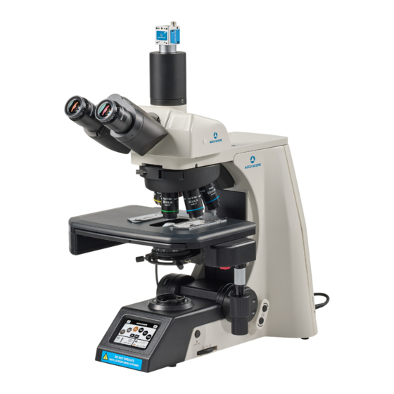
RC500 System) and how each component functions. RC500 System Upper-Body Components (Front) Camera: This camera takes the images seen on the RC500 Software and provides live feed of the image for evaluation of slides. Camera Mount: Adapter that attaches the camera to the RC500 body. - Page 9 Device Description RC500 System Mid-Body Components (Front) Nosepiece: Enables user to switch objectives. Objectives: Provides magnification of 4x, 10x, 20x, 40x, and 60x or others as equipped. Slide Holder: Allows user to mount up to two standard sized slides at one time.
- Page 10 X-stage Movement Knob: Moves stage side to side (Left/Right). LCD Screen: Displays RC500 Settings. Must be used to change objectives when used as a stand-alone microscope. Never attempt to move the objectives by hand when the microscope is powered on.
-
Page 11: Objective Switching Buttons
Focusing Knob: Page 13. Allows user to move stage up/down along Z axis to focus the image on the sample. Coarse, Fine, Ultra Fine Focus Toggle Button: Controls sensitivity of Z-axis Capture Button: Not used in RC500 Applications. Objective Switching Buttons: o Top: Nosepiece moves clockwise. - Page 12 Limit Button: Not Enabled Light Direction Button: Allows user to toggle between Transmitted Light and Reflected Light (Not enabled on the RC500) for changing light intensity. Brightness Adjustment Knob: Allows user to adjust illumination. ACCU-SCOPE RC500 User Manual 250227 Ver.
- Page 13 RC500 System (Back) Computer Connector: Connects the RC500 System to the computer. Illumination Lamphouse Connector: Connects the light source to the RC500 main body. Light Source: Generates light for slide illumination. 3mm Hex Wrench: Used for tightening connections on the RC500 System.
- Page 14 Web Camera Power Button USB Port Speakers *Specifications are subject to change. Integration fees may apply to use the RC500 with an existing computer system. A Computer is required for RC500 software operation. ACCU-SCOPE RC500 User Manual 250227...
- Page 15 2- Type A USB Ports (Stage and Microscope) 1- Type A USB SS-Port (Super Speed Reserved for Camera) Type C USB SS-Port Monitor display controls are located above the power button. ACCU-SCOPE RC500 User Manual 250227 Ver.
- Page 16 Device Description RC500 Software The RC500 Software enables the user to: View and capture live images from the RC500 System Control the motorized components of the RC500 System including: Objectives, Slide Position, Focus, and Illumination Save images to local computer files and/or upload files to a shared drive.
- Page 17 Device Description RC500 Remote Access Software RC500 Remote Access Software: The RC500 System can be accessed by a remote user utilizing a Remote Access Software such as TeamViewer. Other remote access software may be used. This software enables the remote expert to: ...
-
Page 18: Device Operation
Power On The steps below describe how to power on the unit. 1. Press the power switch of the main body, located on the back side of the system, to the on position. ACCU-SCOPE RC500 User Manual 250227 Ver. - Page 19 -The stage will move up and down. Do not attempt to load a slide or touch the stage during this process. The front display will show a loading indicator, then the main screen will appear. ACCU-SCOPE RC500 User Manual 250227...
- Page 20 Device Operation 2. Turn on the RC500 Computer by pressing the button located on the right side of the speakers. -There is a switch located under the wireless mouse to turn it on. If the keyboard or mouse is ever unresponsive, replace their batteries.
-
Page 21: Manual Operation
RC500 Software Manual Operation The RC500 system can be used independently of the RC500 service. Below are instructions for operating the RC500 system manually. Mounting the Specimen The steps below describe how to mount the specimen to be examined. 1. Line up the slide, specimen side up, with the opening at the front of the slide holder. There is a lip on the slide holder that the slide must be inserted onto. -
Page 22: Motorized Stage
RC500 Software Motorized Stage The Motorized Stage on the RC500 is a precision instrument capable of accuracy in microns. It is an actively engaged motor that should only be handled by those who are familiar with the delicacy of such instruments. -
Page 23: Viewing The Slide
If you are using the software, click the Load New Sides button. The stage will move to a convenient slide loading position for easier access. Viewing the Slide To view the slide utilizing the eyepieces, ensure that the eyepiece diopters are both set to 0 or set to your individual prescription. ACCU-SCOPE RC500 User Manual 250227 Ver. -
Page 24: Adjusting The Focus Manually
1. To move slide forwards/backwards, use the Y-Stage Movement Knob (larger knob on the top). 2. To move slide side to side, use the X-Stage Movement Knob. Note: The stage must be connected to a power source to be able to move both manually and through the RC500 Software. ACCU-SCOPE RC500 User Manual 250227... -
Page 25: Changing Objectives Manually
Do Not grab the objectives or nosepiece to physically rotate another objective into position. Doing so will damage the motorized nosepiece. Objectives can be changed on the RC500 System manually using the following methods: 1. Touch the desired objective on the display screen. The objective that is currently active will be illuminated orange. -
Page 26: Adjusting The Condenser Aperture
The level of illumination will be displayed on the front screen of the system. If you are having difficulty controlling the light levels, ensure the Light Direction Button is depressed for Transmitted Light. Reflected Light Illumination is not used on the RC500. Adjusting the Condenser Aperture The aperture has been pre-set during installation. -
Page 27: Enabling The Focus Compensation
1. Press the Settings button on the front display. 2. Check box to enable focus compensation. 3. Exit settings by pressing the gear icon. You will see “FC” in the corner to indicate that focus compensation is active. ACCU-SCOPE RC500 User Manual 250227 Ver. -
Page 28: Rc500 Software
RC500 Software RC500 Software This section describes how to use the RC500 Software. This software is located on the main screen of the RC500 workstation. Note: Ensure all RC500 components are powered on and connected to the workstation prior to initiating the software. If a component is not connected and/or is not powered on, an error message will be produced upon software initiation. -
Page 29: Adjusting The Focus With The Rc500 Software
The steps below describe how to adjust the focus of the unit with the Software. RC500 Adjusting the focus using the RC500 Software can be done three different ways: Using the focus arrows on the screen. Using the wheel on the mouse (forward = down, backward= up) ... - Page 30 Cycle Focus. The microscope will cycle using the Time, Step Width, and Range settings. You can adjust these to cover greater or smaller areas as needed. -This feature does NOT replace Auto Focus. Keyboard Shortcut: CTRL+F (toggle on/off) ACCU-SCOPE RC500 User Manual 250227 Ver.
-
Page 31: Moving The Slide Through The Rc500 Software
Moving the Slide through the RC500 Software The steps below describe how to move the slide using the RC500 software interface: 1. In the map, click on the area of the slide you would like to view using the map. - Page 32 4. Under “Mouse”, you can select the “Hand” feature to click and drag the field of view in your desired direction. -Click to center is set by default and will center an area of interest on the screen when clicked. ACCU-SCOPE RC500 User Manual 250227 Ver.
-
Page 33: Changing Objectives In The Rc500 Software
When the button is highlighted blue, the directional controls for the stage will be implemented. Changing Objectives in the RC500 Software 1. When using the RC500 Software, objectives can be changed by selecting the desired objective located at the top right of the toolbar. -
Page 34: Adjusting Illumination In The Rc500 Software
In Addition to optical magnification, there is also a 3.0x digital zoom slider on the top of the screen. Adjusting Illumination in the RC500 Software The illumination of the RC500 System can be adjusted by using the sliding adjustment featured under the “Illumination” tab. -
Page 35: Dropping Pins In The Rc500 Software
RC500 Software Dropping Pins in the RC500 Software Pins can be placed to mark areas of note simply by right clicking of the mouse. After you place a pin, you can name it or add a short note, and change the color. Click in the image away from the pin to finish the pin edit. -
Page 36: Capturing Images
Saving Captured Images to Local Computer Files Images taken using the RC500 Software can be saved to the local Computer files for transfer into patient files in the practice management system. Images can be saved as “TIFF”, “JPEG” or “PNG” files. -
Page 37: Systematic Field Screening
When unchecked, Synchronous Mode would always show live images and have the microscope wait a certain amount of time before moving on. Asynchronous Mode is preferred for overall faster screening time and quality. ACCU-SCOPE RC500 User Manual 250227 Ver. - Page 38 RC500 Software When prompted, draw a box around the desired region for screening. By selected next in the bottom right corner, the RC500 will automatically begin screening and attempting to focus each field of view for your selected region. Use the arrows on screen or on the keyboard to view each screening segment. You can also select specific screened regions of the slide with your mouse.
- Page 39 If you paused a screening to begin evaluating and wish to continue the screening, select the button. Next, click the last screened region. A button will appear where you can resume screening. Regions that have previously been examined will be highlighted in green. ACCU-SCOPE RC500 User Manual 250227 Ver.
-
Page 40: Remote Access Software
Remote Access Software You will need remote access software to be installed on both the RC500 computer and any remote computer to be used during consultation. Regardless of the remote access software being used, the steps to connect from a remote computer to the RC500 are similar. -
Page 41: Hot Keys
Once you become acclimated with the RC500, you can then become proficient in it by using Hot Keys. These Hot Keys have been programmed to provide an efficient alternative to mouse clicks in the RC500 software interface. The list of Hot Keys can be found behind the: ACCU-SCOPE RC500 User Manual 250227 Ver. -
Page 42: Maintenance
Lens surfaces can be wiped utilizing lens cleaning tissue or similar cloth wipes. Accumulated dirt on metal surfaces should be cleaned with a damp cloth. Do not use organic solvents for cleaning. Cover the system with included dust cover when not in use. ACCU-SCOPE RC500 User Manual 250227 Ver. -
Page 43: Troubleshooting
Maintenance Troubleshooting Under certain conditions, performance of the RC500 may be adversely affected by factors other than defects. If a problem occurs, please review the following list and take remedial action as needed. Before you call, check the following issues and resolutions listed below:... -
Page 44: Error Messages
Open to the proper setting Condenser position too low Position the condenser slightly lower than the upper limit Error Messages Below are the error messages that may appear during the start-up of the RC500 software. Problem Cause Corrective Measure Error Message:... -
Page 45: Mechanical Issues
Contact ACCU-SCOPE initialization of microscope initialization Nosepiece will not move or will Connection to nosepiece is unstable Contact ACCU-SCOPE for instructions on how move in disobedient ways (typically from transit) to confirm connections Stage is making loud noise Motor on stage was physically... - Page 46 4x on the RC500 software. The Lines should be improved but may still be present to a tolerable degree. Black Screen in Software: Should the software open and the camera not communicate any image, the camera may not be plugged into the USB-3 SS (Super Speed) port.
-
Page 47: Maintenance Schedule
Maintenance Maintenance Schedule The RC500 system should be regularly maintained and calibrated on an annual basis. It is the responsibility of the user to schedule this maintenance and keep record of activities. For more information on maintenance of the RC500 system, contact ACCU-SCOPE Customer Care directly. -
Page 48: Specifications And Environmental Conditions
***After Truck Shipment, store the microscope should at room temperature for 24 hours before it can be powered on to prevent condensation from damaging the machine or electrical parts.*** Electrical Specifications Input Voltage 100-240V Input Current 1.5 A ACCU-SCOPE RC500 User Manual 250227 Ver. -
Page 49: Warranty Details
Warranty Terms ACCU-SCOPE RC500 components are warranted to be free from defects in materials and workmanship for a period specified within your sales order agreement. The warranty terms will start from the date of initial installation. ACCU-SCOPE’s liability under the agreement is limited to the following: ... -
Page 50: Disposal
ACCU-SCOPE, FOB city destination within the Continental United States. Transportation beyond these limits will be charged to purchaser. The warranty set out in above paragraph is the exclusive warranty made by ACCU-SCOPE and is in lieu of all other warranties (except for specific product performance warranties), whether written, oral, or implied, including any warranty of merchantability or fitness for a particular purpose, and shall be customer’s sole remedy and ACCU-SCOPE’s sole... -
Page 51: Labeling
Equipment must not be disposed of as unsorted unsorted municipal municipal waste. waste (WEEE) Indicates the need for the user to consult the instructions for use prior to operating the device. Follow Instructions RC500 Product Label ACCU-SCOPE RC500 User Manual 250227 Ver.
Need help?
Do you have a question about the RC500 and is the answer not in the manual?
Questions and answers