Table of Contents
Advertisement
Quick Links
OPERATOR'S MANUAL
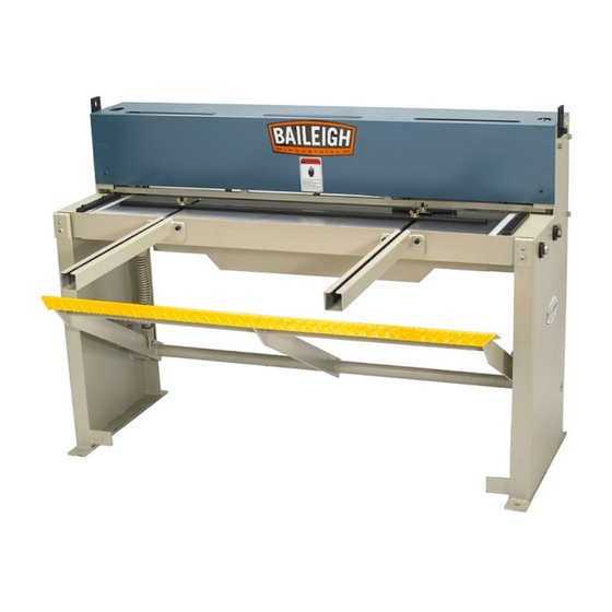
FOOT SHEAR
MODEL: SF-5216
Baileigh Industrial Holdings LLC
P.O. Box 531
Manitowoc, WI 54221-0531
Phone: 920.684.4990
Fax: 920.684.3944
Baileigh-Sales@jpwindustries.com
REPRODUCTION OF THIS MANUAL IN ANY FORM WITHOUT WRITTEN APPROVAL OF BAILEIGH INDUSTRIAL
HOLDINGS LLC IS PROHIBITED. Baileigh Industrial Holdings LLC, Inc. does not assume and hereby disclaims any
liability for any damage or loss caused by an omission or error in this Operator's Manual, resulting from accident,
negligence, or other occurrence.
Rev. 05/2021
© 2021 Baileigh Industrial Holdings LLC
Advertisement
Table of Contents

Related Manuals for Baileigh Industrial SF-5216


Summary of Contents for Baileigh Industrial SF-5216
- Page 1 REPRODUCTION OF THIS MANUAL IN ANY FORM WITHOUT WRITTEN APPROVAL OF BAILEIGH INDUSTRIAL HOLDINGS LLC IS PROHIBITED. Baileigh Industrial Holdings LLC, Inc. does not assume and hereby disclaims any liability for any damage or loss caused by an omission or error in this Operator’s Manual, resulting from accident, negligence, or other occurrence.
-
Page 2: Table Of Contents
Table of Contents THANK YOU & WARRANTY ..................1 INTRODUCTION ......................3 GENERAL NOTES ......................3 SAFETY INSTRUCTIONS ....................4 SAFETY PRECAUTIONS ....................6 Dear Valued Customer: ....................6 TECHNICAL SPECIFICATIONS ..................9 TECHNICAL SUPPORT ....................9 UNPACKING AND CHECKING CONTENTS ..............10 TRANSPORTING AND LIFTING .................. -
Page 3: Thank You & Warranty
THANK YOU & WARRANTY Thank you for your purchase of a machine from Baileigh Industrial Holdings LLC. We hope that you find it productive and useful to you for a long time to come. Inspection & Acceptance. Buyer shall inspect all Goods within ten (10) days after receipt thereof. Buyer’s payment shall constitute final acceptance of the Goods and shall act as a waiver of the Buyer’s rights to inspect or reject the... - Page 4 • A 30% re-stocking fee applies to all returns. Baileigh Industrial Holdings LLC makes every effort to ensure that our posted specifications, images, pricing and product availability are as correct and timely as possible. We apologize for any discrepancies that may occur. Baileigh Industrial Holdings LLC reserves the right to make any and all changes deemed necessary in the course of business including but not limited to pricing, product specifications, quantities, and product availability.
-
Page 5: Introduction
INTRODUCTION The quality and reliability of the components assembled on a Baileigh Industrial Holdings LLC machine guarantee near perfect functioning, free from problems, even under the most demanding working conditions. However, if a situation arises, refer to the manual first. If a solution cannot be found, contact the distributor where you purchased our product. -
Page 6: Safety Instructions
IMPORTANT PLEASE READ THIS OPERATORS MANUAL CAREFULLY It contains important safety information, instructions, and necessary operating procedures. The continual observance of these procedures will help increase your production and extend the life of the equipment. SAFETY INSTRUCTIONS LEARN TO RECOGNIZE SAFETY INFORMATION This is the safety alert symbol. -
Page 7: Protect Eyes
SAVE THESE INSTRUCTIONS. Refer to them often and use them to instruct others. PROTECT EYES Wear safety glasses or suitable eye protection when working on or around machinery. PROTECT AGAINST NOISE Prolonged exposure to loud noise can cause impairment or loss of hearing. -
Page 8: Safety Precautions
SAFETY PRECAUTIONS Metal working can be dangerous if safe and proper operating procedures are not followed. As with all machinery, there are certain hazards involved with the operation of the product. Using the machine with respect and caution will considerably lessen the possibility of personal injury. However, if normal safety precautions are overlooked or ignored, personal injury to the operator may result. - Page 9 8. Do not force tool. Your machine will do a better and safer job if used as intended. DO NOT use inappropriate attachments in an attempt to exceed the machine’s rated capacity. 9. Use the right tool for the job. DO NOT attempt to force a small tool or attachment to do the work of a large industrial tool.
- Page 10 Hazard Signs...
-
Page 11: Technical Specifications
TECHNICAL SPECIFICATIONS Maximum Shear Length 52” (1321mm) 16 ga. (1.52mm) mild steel* Maximum Material Thickness 20 ga. (.912mm) stainless steel** Minimum Material Thickness 24 ga. (0.607mm) Front Gate Length 24” (609mm) Back Gate Length 24” (609mm) Blade Angle 1° Power Requirements Manual Shipping Dimensions (L x W x H) 67”... -
Page 12: Unpacking And Checking Contents
UNPACKING AND CHECKING CONTENTS Your Baileigh machine is shipped complete. Separate all parts from the packing material and check each item carefully. Make certain all items are accounted for before discarding any packing material. WARNING: SUFFOCATION HAZARD! Immediately discard any plastic bags and packing materials to eliminate choking and suffocation hazards to children and animals. -
Page 13: Transporting And Lifting
TRANSPORTING AND LIFTING NOTICE: Lifting and carrying operations should be carried out by skilled workers, such as a truck operator, crane operator, etc. If a crane is used to lift the machine, attach the lifting chain carefully, making sure the machine is well balanced. Follow these guidelines when lifting with truck or trolley: •... -
Page 14: Installation
INSTALLATION IMPORTANT: Consider the following when looking for a suitable location to place the machine: • Overall weight of the machine. • Weight of material being processed. • Sizes of material to be processed through the machine. • Space needed for auxiliary stands, work tables, or other machinery. •... -
Page 15: Overall Dimensions
OVERALL DIMENSIONS 61.20" [1554.59] 57.75" [1466.87] 73.75" [1873.37] 9.50" [241.28] 30.50" [774.70] 33.75" [857.26] 22.44" [569.93] 23.25" [590.65]... -
Page 16: Getting To Know Your Machine
GETTING TO KNOW YOUR MACHINE... - Page 17 Item Description Function Foot Pedal Step on the pedal to complete the cut Material Support Arm Supports larger sheets of material Graduated Side Gauge Keeps material perpendicular to blade Lifting Brackets Used for lifting machine Oiling Cap Access to oiling the top blade slide Hold Down Cover Covers hold downs and upper blade travel Shear Table...
-
Page 18: Machine Assembly
MACHINE ASSEMBLY Foot Pedal Installation 1. Loosen the set screw (A) on each pedal pivot pin (B) and slide the pin out of the pivot block. 2. Lightly grease the inside of the pivot tube on each end of the pedal assembly about 3”-4”... -
Page 19: Installing Front Extension Rails
Installing Front Extension Rails 1. Remove the (4) cap screws and flatwashers (A) to the machined rail pads. 2. Position the rail onto the mounting pads and loosely install the capscrews and flatwashers. 3. Line up the rail channel with the channel on the table, making sure the top machined surfaces are flush. -
Page 20: Installing The Rear Gauge Shafts
Installing the Rear Gauge Shafts Note: When using for the first time, verify the dimension “X” from the face of the lower blade to the front edge of the stop angle. 1. Slide the gauge shafts into the housing hole with the scales facing up and lightly tighten each set screw (A). -
Page 21: Machine Functions
MACHINE FUNCTIONS Foot Pedal Stepping down on the foot pedal does two things. First it lowers the hold downs which keep the piece part from moving during a cut. Second it lowers the top blade past the lower blade to shear the material. Front and Rear Extension Rods The front extensions help support large sheets of material and the rear extensions provide support for the micro-adjusters. -
Page 22: Material Support Arm
Material Support Arm CAUTION: When handling large piece parts, you may require assistance in handling the piece as it exits the blades. Failure to adequately support the piece part may result in the piece falling and causing bodily injury. The two material support arms (A) attach to the front of the shear. -
Page 23: Shearing Cycle
SHEARING CYCLE WARNING: Always wear proper eye protection with side shields, safety footwear, and leather gloves to protect from burrs and sharp edges. The shearing blade poses an amputation hazard. Make sure no body part or clothing is near the specific hazard. Failure to follow this warning could result in severed or crushed fingers. -
Page 24: Lubrication And Maintenance
LUBRICATION AND MAINTENANCE WARNING: Make sure the air supply is OFF before working on the machine. Maintenance should be performed on a regular basis by qualified personnel. Always follow proper safety precautions when working on or around any machinery. Daily Maintenance •... -
Page 25: Replacing The Shear Blades
REPLACING THE SHEAR BLADES The blades on the Baileigh SF-5216 have multiple usable edges. If you have not already used both cutting edges on the top blade you can rotate it end for end to expose a sharp edge. The bottom blade has four usable edges. - Page 26 5. When the blade is in position, secure with the bolts and washers that were removed previously. 6. Set the gap to .005” (.12mm) making sure the blades are parallel along the entire length. 7. The blade gap adjustment screws (B) were preset at the factory. ADJUST ONLY IF ABSOLUTELY NECESSARY.
-
Page 27: To Rotate Or Replace The Bottom Blade
To Rotate or Replace the Bottom Blade: WARNING: The shearing blade poses an amputation hazard. Always wear proper safety footwear and leather gloves to protect from burrs and sharp edges. Failure to follow this warning could result in severed or crushed fingers. 1. -
Page 28: Ram Ways Adjustment
RAM WAYS ADJUSTMENT The ram ways are adjustable to compensate for wear which can be expected after years of service. Premature wear can occur if the machine is not properly leveled which causes a twisting action. The proper running clearance should be from 0.001” - 0.002” (0.038mm - 0.050mm). This clearance should be checked periodically and maintained to extend blade life and to hold accuracy of the shear. -
Page 29: Material Selection
MATERIAL SELECTION CAUTION: It must be determined by the customer that materials being processed through the machine are NOT potentially hazardous to operator or personnel working nearby. When selecting materials keep these instructions in mind: • Material must be clean and dry. (without oil) •... -
Page 30: Blade Clearance
BLADE CLEARANCE The blade gap on the shear was set at the factory. At this setting it will shear mild steel up to 16ga. (1.52mm) and stainless steel up to 20ga. (.912mm). To measure the blade gap, gradually lower the top blade and measure the gap going from left to right while facing the rear of the machine. -
Page 31: Parts Identification Drawing
PARTS IDENTIFICATION DRAWING... -
Page 34: Parts List
Parts List Item Part No. Description SF5216-1 Table SF5216-2 Cutter Bar SF5216-3 Hold Down SF5216-4 Right-Hand Slide Panel SF5216-5 Left-Hand Slide Panel SF5216-6 Front Arm Extender SF5216-7 5/8" Nut SF5216-8 Spring (602635) SF5216-9 Stud 5/8" SF5216-10 1/2" Nut SF5216-11 1/2" Washer SF5216-12 I Connection SF5216-13... - Page 35 Item Part No. Description SF5216-34 M10 x25 SHCS SF5216-35 DB10-2 Washer SF5216-36 Hook Ring SF5216-37 4" x 1" SHCS SF5216-38 DB10-2 Washer SF5216-39 M10 x 25 SHCS SF5216-40 5/8" x 1-3/4" HHCS ∅50 x ∅16 x 25 Washer SF5216-41 DB16 Washer SF5216-42 SF5216-43 3/8"...
- Page 36 Item Part No. Description SF5216-68 3/8" x 1" HHCS SF5216-69 3/8" Nut SF5216-70 "T" 3/8" Screw SF5216-71 Stop, Front Material SF5216-72 3/8" Washer SF5216-73 3/8" Wing Nut SF5216-74 3/8" x 1-1/2" SHCS SF5216-75 3/8" Washer SF5216-76 "T" 3/8" Screw SF5216-77 Angel Gauge SF5216-78 3/8"...
-
Page 37: Troubleshooting
TROUBLESHOOTING FAULT PROBABLE CAUSE REMEDY Dull blades. Turn or sharpen blades. Excessive blade clearance. Adjust blade gap. BURR ON SHEARED Excessive clearance in ram Make adjustment to reduce EDGE ways. clearance. Poor grade of material. Select vendor with better quality material that is consistent. - Page 38 NOTES...
- Page 39 NOTES...
- Page 40 BAILEIGH INDUSTRIAL HOLDINGS LLC 1625 D , WI 54220 UFEK RIVE ANITOWOC : 920. 684. 4990 F : 920. 684. 3944 HONE www.baileigh.com...
Need help?
Do you have a question about the SF-5216 and is the answer not in the manual?
Questions and answers