Table of Contents
Advertisement
Quick Links
OPERATOR'S MANUAL
GEAR DRIVE DRILL PRESS
MODEL: DP-1000G
Baileigh Industrial Holdings LLC
P.O. Box 531
Manitowoc, WI 54221-0531
Phone: 920.684.4990
Fax: 920.684.3944
sales@baileigh.com
REPRODUCTION OF THIS MANUAL IN ANY FORM WITHOUT WRITTEN APPROVAL OF BAILEIGH INDUSTRIAL
HOLDINGS LLC IS PROHIBITED. Baileigh Industrial Holdings LLC, Inc. does not assume and hereby disclaims any
liability for any damage or loss caused by an omission or error in this Operator's Manual, resulting from accident,
negligence, or other occurrence.
Rev. 03/2021
© 2021 Baileigh Industrial Holdings LLC
Advertisement
Table of Contents

Related Manuals for Baileigh Industrial DP-1000G


Summary of Contents for Baileigh Industrial DP-1000G
- Page 1 REPRODUCTION OF THIS MANUAL IN ANY FORM WITHOUT WRITTEN APPROVAL OF BAILEIGH INDUSTRIAL HOLDINGS LLC IS PROHIBITED. Baileigh Industrial Holdings LLC, Inc. does not assume and hereby disclaims any liability for any damage or loss caused by an omission or error in this Operator’s Manual, resulting from accident, negligence, or other occurrence.
-
Page 2: Table Of Contents
Table of Contents THANK YOU & WARRANTY ..................1 INTRODUCTION ......................3 GENERAL NOTES ......................3 SAFETY INSTRUCTIONS ....................4 SAFETY PRECAUTIONS ....................6 Dear Valued Customer: ....................6 MACHINE DESCRIPTION ....................8 TECHNICAL SPECIFICATIONS ..................8 TECHNICAL SUPPORT ....................8 UNPACKING AND CHECKING CONTENTS .............. - Page 3 Electrical Box Parts List – J ..................38 ELECTRICAL SCHEMATIC ..................39...
-
Page 4: Thank You & Warranty
THANK YOU & WARRANTY Thank you for your purchase of a machine from Baileigh Industrial Holdings LLC. We hope that you find it productive and useful to you for a long time to come. Inspection & Acceptance. Buyer shall inspect all Goods within ten (10) days after receipt thereof. Buyer’s payment shall constitute final acceptance of the Goods and shall act as a waiver of the Buyer’s rights to inspect or... - Page 5 We apologize for any discrepancies that may occur. Baileigh Industrial Holdings LLC reserves the right to make any and all changes deemed necessary in the course of business including but not limited to pricing, product specifications, quantities, and product availability.
-
Page 6: Introduction
INTRODUCTION The quality and reliability of the components assembled on a Baileigh Industrial Holdings LLC machine guarantee near perfect functioning, free from problems, even under the most demanding working conditions. However, if a situation arises, refer to the manual first. If a solution cannot be found, contact the distributor where you purchased our product. -
Page 7: Safety Instructions
IMPORTANT PLEASE READ THIS OPERATORS MANUAL CAREFULLY It contains important safety information, instructions, and necessary operating procedures. The continual observance of these procedures will help increase your production and extend the life of the equipment. SAFETY INSTRUCTIONS LEARN TO RECOGNIZE SAFETY INFORMATION This is the safety alert symbol. - Page 8 SAVE THESE INSTRUCTIONS. Refer to them often and use them to instruct others. PROTECT EYES Wear safety glasses or suitable eye protection when working on or around machinery. PROTECT AGAINST NOISE Prolonged exposure to loud noise can cause impairment or loss of hearing.
-
Page 9: Safety Precautions
SAFETY PRECAUTIONS Metal working can be dangerous if safe and proper operating procedures are not followed. As with all machinery, there are certain hazards involved with the operation of the product. Using the machine with respect and caution will considerably lessen the possibility of personal injury. However, if normal safety precautions are overlooked or ignored, personal injury to the operator may result. - Page 10 8. Do not force tool. Your machine will do a better and safer job if used as intended. DO NOT use inappropriate attachments in an attempt to exceed the machine’s rated capacity. 9. Use the right tool for the job. DO NOT attempt to force a small tool or attachment to do the work of a large industrial tool.
-
Page 11: Machine Description
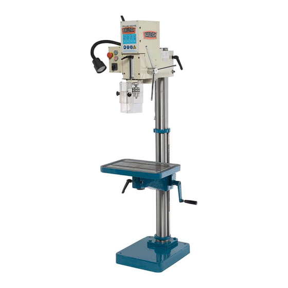
MACHINE DESCRIPTION The Baileigh DP-1000G is a very economical gear head drill press that can run in any fabrication or machine shop using only 110 volts of power. It can drill through mild steel with up to a 1" (25.4mm) drill bit. It comes standard with a heavy cast iron base and adjustable table. -
Page 12: Unpacking And Checking Contents
UNPACKING AND CHECKING CONTENTS Your Baileigh machine is shipped complete. Separate all parts from the packing material and check each item carefully. Make certain all items are accounted for before discarding any packing material. WARNING: SUFFOCATION HAZARD! Immediately discard any plastic bags and packing materials to eliminate choking and suffocation hazards to children and animals. -
Page 13: Transporting And Lifting
TRANSPORTING AND LIFTING NOTICE: Lifting and carrying operations should be carried out by skilled workers, such as a truck operator, crane operator, etc. If a crane is used to lift the machine, attach the lifting chain carefully, making sure the machine is well balanced. Follow these guidelines when lifting with truck or trolley: •... -
Page 14: Installation
INSTALLATION IMPORTANT: Consider the following when looking for a suitable location to place the machine: • Overall weight of the machine. • Weight of material being processed. • Sizes of material to be processed through the machine. • Space needed for auxiliary stands, work tables, or other machinery. •... -
Page 15: Overall Dimensions
OVERALL DIMENSIONS... -
Page 16: Getting To Know Your Machine
GETTING TO KNOW YOUR MACHINE... - Page 17 Item Description Function Base Support the drill press Loosen to allow the table to rotate on its center axis. Table Rotation Lock NEVER OPERATE THE MACHINE WHEN UNLOCKED. Work Table Work surface with T-slots Chuck Holds various tools for drilling and tapping Adjustable guard to cover the chuck and restrict Drill Guard access during operation...
-
Page 18: The Drill Head
The Drill Head The drill head attaches to the upper column. It houses the motor, spindle, and speed controls. Attached to it is the electrical enclosure, the protective guard, the work light. The drill head can be lowered, raised, and rotated on the column as needed. -
Page 19: Electrical
ELECTRICAL CAUTION: HAVE ELECTRICAL UTILITIES CONNECTED TO MACHINE BY A CERTIFIED ELECTRICIAN! Check if the available power supply is the same as listed on the machine nameplate. WARNING: Make sure the grounding wire (green) is properly connected to avoid electric shock. DO NOT switch the position of the green grounding wire if any electrical plug wires are switched during hookup. - Page 20 • Improper connection of the equipment-grounding conductor can result in risk of electric shock. The conductor with insulation having an outer surface that is green with or without yellow stripes is the equipment-grounding conductor. If repair or replacement of the electric cord or plug is necessary, do not connect the equipment-grounding conductor to a live terminal.
-
Page 21: Operation
OPERATION CAUTION: Always wear proper eye protection with side shields. Restrain and contain long hair, loose or baggy clothing and remove jewelry to prevent entanglement. Safety guard must be properly positioned. 1. Load and secure the piece part to the table. 2. -
Page 22: Material Selection
13. At the end of a drilling or tapping operation, press the stop button (I) to turn OFF the machine. In the event of incorrect operation or dangerous conditions, the machine can be stopped immediately by pressing the E-STOP button (H). Twist the button clockwise (cw) to reset. MATERIAL SELECTION CAUTION: It must be determined by the customer that materials being... -
Page 23: Lubrication And Maintenance
LUBRICATION AND MAINTENANCE WARNING: Make sure the electrical disconnect is OFF before working on the machine. Maintenance should be performed on a regular basis by qualified personnel. Always follow proper safety precautions when working on or around any machinery. Daily Maintenance •... -
Page 24: Drill Head Diagram - A
DRILL HEAD DIAGRAM – A... -
Page 25: Drill Head Parts List - A
Drill Head Parts List – A Item Part No. Ref. No. Description DP1000G-A1 2X08700 Spindle Housing DP1000G-A2 2X08404 Gearbox DP1000G-A-03 2X08719 Spindle Sleeve DP1000G-A-04 2X08740-5 Feed Shaft Complete DP1000G-WGBC 2X08720 Worm Gear Unit DP1000G-A6 2X08702 Front Cover DP1000G-A8 4U08705 Electric Box Cover DP1000G-A-9 3R00014 Locking Lever... -
Page 26: Gearbox Diagram - B
GEARBOX DIAGRAM – B... -
Page 27: Gearbox Parts List - B
Gearbox Parts List – B Item Part No. Ref. No. Description DP1000G-B1 Rotor shaft DP1000G-B2 2X08404-2 2nd Shaft complete DP1000G-B3 2X08404-3 3rd Shaft complete DP1000G-B4 2X08422 Gear box complete DP1000G-B5 4B00174 Ring DP1000G-B6 4B00173 Ring DP1000G-7-2X08536 2X08536 Gear selector arm DP1000G-B8 4RS0653-1 Gear lever... -
Page 28: Rotor Shaft Diagram - C
ROTOR SHAFT DIAGRAM – C... -
Page 29: Rotor Shaft Parts List - C
Rotor Shaft Parts List – C Item Part No. Ref. No. Description DP1000G-C1 4B00137 Washer DP1000G-C2 3L11003 Ball bearing 6203 DP1000G-C-3 2H07969 Gear 15-1, 5 DP1000G-C4 2D17014 Spacing sleeve 17x14 DP1000G-C5 2H07972 Gear 39-1, 5 DP1000G-C6 2D17002 Spacing sleeve 17x2 DP1000G-C7 3L11003 Ball bearing 6203... -
Page 30: 2Nd Shaft Diagram - D
2nd SHAFT DIAGRAM – D... -
Page 31: 2Nd Shaft Parts List - D
2nd Shaft Parts List – D Item Part No. Ref. No. Description DP1000G-D1 4B00138 Washer C-138 DP1000G-D2 3L11003 Ball bearing 6203 DP1000G-D3 2D00009 Spacing sleeve 17x3, 5 DP1000G-2-4 2H07971 Gear 32-2 DP1000G-D5 2D17038 Spacing sleeve 17x38 DP1000G-2-6 2H07970 Gear 15-2 DP1000G-D7 2D17005 Spacing sleeve 17x5... -
Page 32: 3Rd Shaft Diagram - E
3rd SHAFT DIAGRAM – E... -
Page 33: 3Rd Shaft Parts List - E
3rd Shaft Parts List – E Item Part No. Ref. No. Description DP1000G-E1 4B00138 Cover C-138 DP1000G-E2 3L16002 Ball bearing 6302 DP1000G-E-3 3015002 Spacing sleeve 15x2 DP1000G-E4 3C01117 Circlip SgA 15 DP1000G-5-Gear 2X08413 Gear complete 32-2 DP1000G-E6 2T04254 Clutch C 4254 DP1000G-7 2X08411 Gear complete 49-2... -
Page 34: Column Diagram - F
COLUMN DIAGRAM – F... -
Page 35: Column Parts List - F
Column Parts List – F Item Part No. Ref. No. Description DP1000G-F-1 2W07802 Base plate DP1000G-F2 4X08300 Column L=1500 DP1000G-F3 2X08723 Table arm complete DP1000G-F4 2WS1231 Table DP1000G-Upper 2X08445 Rack Column Rack DP1000G-F6 2T07146 DP1000G-F-7 2Y08723 Table arm DP1000G-F 2X08720-1 Worm gear complete DP1000G-F8 2RS1182... -
Page 36: Worm Gear Box Complete Diagram - G
WORM GEAR BOX COMPLETE DIAGRAM – G Worm Gear Box Complete Parts List – G Item Part No. Ref. No. Description DP1000G-G1-9 2X08720 Worm gear box Complete DP1000G-G1 2N08720 Worm gear box DP1000G-13 2AS1202 Shaft DP1000G-12-Gear 2HS1201 Gear DP1000G-11 2D20008 Spacer 20x8 DP1000G-10 2IS1203... -
Page 37: Feedshaft Diagram - H
FEEDSHAFT DIAGRAM – H Feed Shaft Parts List – H Item Part No. Ref. No. Description DP1000G-H1 4T08715 Spring housing DP1000G-4C03026 4C03026 Clock Spring w/Housing DP1000G-H3 2108708 Feed shaft DP1000G-H-4 4S04211 Screw DP1000G-H5 2E08722 Feed lever DP1000G-H6 3R02003 Handle ball... -
Page 38: Spindle Sleeve Diagram - I
SPINDLE SLEEVE DIAGRAM – I... -
Page 39: Spindle Sleeve Parts List - I
Spindle Sleeve Parts List – I Item Part No. Ref. No. Description DP1000G-I1 3M06005 Nut MK5 DP1000G-I2 4B00155 Locking washer DP1000G-I3 3L11005 Ball bearing 6205 DP1000G-I4 2G08709 Spindle sleeve DP1000G-I5 2I08420 Rack DP1000G-I6 4B03769 Washer DP1000G-I7 3L51006 Taper roller bearing 30206 DP1000G-I8 2TS1106 Roller bearing cover... -
Page 40: Electric Box Diagram - J
ELECTRIC BOX DIAGRAM – J... - Page 41 Electrical Box Parts List – J Item Part No. Ref. No. Description DP1000G-J1 4U08705 Electric box cover DP1000G-J2 2L08712 Rail anchor DP1000G-J3 3E10604 Motor Protector 380/50 DP1000G-J4 2E08713 Electric box distance tube DP1000G-J5 4L08706 Anchor plate DP1000G-J6 4L08711-3 Electric box plate DP1000G-J7 3E16227 Emergency stop...
- Page 42 ELECTRICAL SCHEMATIC...
- Page 43 Item Part No. Description DP1000G-KM Motor Contactor DP1000G-FR Thermal Overload DP1000G-XFRMR Transformer 60VA DP1500G-E Stop Emergency Stop Button DP1500VS-D-01 Push Button (Start) DP1500VS-SB2 Push Button (Stop) DP1000G-Lamp Work Lamp Assembly (no bulb) DP1000G-LED Bulb LED Bulb DP1000G-Run Capacitor Capacitor 90UF 250V. AC (49*102) DP1000G-Start Capacitor Capacitor 250UF 250V.
- Page 44 NOTES BAILEIGH INDUSTRIAL HOLDINGS LLC 1625 D , WI 54220 UFEK RIVE ANITOWOC : 920. 684. 4990 F : 920. 684. 3944 HONE www.baileigh.com...
Need help?
Do you have a question about the DP-1000G and is the answer not in the manual?
Questions and answers