Table of Contents
Advertisement
OPERATOR'S MANUAL
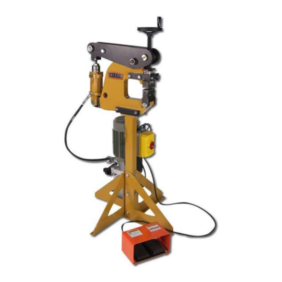
METAL FORMING SHRINKER STRETCHER
MODEL: MSS-14H
Baileigh Industrial, Inc.
P.O. Box 531
Manitowoc, WI 54221-0531
Phone: 920.684.4990
Fax: 920.684.3944
sales@baileighindustrial.com
REPRODUCTION OF THIS MANUAL IN ANY FORM WITHOUT WRITTEN APPROVAL OF BAILEIGH INDUSTRIAL, INC.
IS PROHIBITED. Baileigh Industrial, Inc. does not assume and hereby disclaims any liability for any damage or loss
caused by an omission or error in this Operator's Manual, resulting from accident, negligence, or other occurrence.
Rev. 03/2015
© 2015 Baileigh Industrial, Inc.
Advertisement
Table of Contents

Subscribe to Our Youtube Channel
Related Manuals for Baileigh Industrial MSS-14H


Summary of Contents for Baileigh Industrial MSS-14H
- Page 1 REPRODUCTION OF THIS MANUAL IN ANY FORM WITHOUT WRITTEN APPROVAL OF BAILEIGH INDUSTRIAL, INC. IS PROHIBITED. Baileigh Industrial, Inc. does not assume and hereby disclaims any liability for any damage or loss caused by an omission or error in this Operator’s Manual, resulting from accident, negligence, or other occurrence.
-
Page 2: Table Of Contents
Table of Contents THANK YOU & WARRANTY ..................1 INTRODUCTION ......................3 GENERAL NOTES ......................3 SAFETY INSTRUCTIONS ....................4 SAFETY PRECAUTIONS ....................6 TECHNICAL SPECIFICATIONS ..................8 TECHNICAL SUPPORT ....................8 UNPACKING AND CHECKING CONTENTS ..............9 Cleaning ........................9 TRANSPORTING AND LIFTING .................. -
Page 3: Thank You & Warranty
THANK YOU & WARRANTY Thank you for your purchase of a machine from Baileigh Industrial. We hope that you find it productive and useful to you for a long time to come. Inspection & Acceptance. Buyer shall inspect all Goods within ten (10) days after receipt thereof. Buyer’s payment shall constitute final acceptance of the Goods and shall act as a waiver of the Buyer’s rights to inspect or... - Page 4 A 30% re-stocking fee applies to all returns. Baileigh Industrial makes every effort to ensure that our posted specifications, images, pricing and product availability are as correct and timely as possible. We apologize for any discrepancies that may occur. Baileigh Industrial reserves the right to make any and all changes deemed necessary in the course of business including but not limited to pricing, product specifications, quantities, and product availability.
-
Page 5: Introduction
After receiving your equipment remove the protective container. Do a complete visual inspection, and if damage is noted, photograph it for insurance claims and contact your carrier at once, requesting inspection. Also contact Baileigh Industrial and inform them of the unexpected occurrence. Temporarily suspend installation. -
Page 6: Safety Instructions
IMPORTANT PLEASE READ THIS OPERATORS MANUAL CAREFULLY It contains important safety information, instructions, and necessary operating procedures. The continual observance of these procedures will help increase your production and extend the life of the equipment. SAFETY INSTRUCTIONS LEARN TO RECOGNIZE SAFETY INFORMATION This is the safety alert symbol. - Page 7 SAVE THESE INSTRUCTIONS. Refer to them often and use them to instruct others. PROTECT EYES Wear safety glasses or suitable eye protection when working on or around machinery. HYDRAULIC HOSE FAILURE Exercise CAUTION around hydraulic hoses in case of a hose or fitting failure.
-
Page 8: Safety Precautions
SAFETY PRECAUTIONS Metal working can be dangerous if safe and proper operating procedures are not followed. As with all machinery, there are certain hazards involved with the operation of the product. Using the machine with respect and caution will considerably lessen the possibility of personal injury. However, if normal safety precautions are overlooked or ignored, personal injury to the operator may result. - Page 9 11. Do not overreach. Maintain proper footing and balance at all times. DO NOT reach over or across a running machine. 12. Stay alert. Watch what you are doing and use common sense. DO NOT operate any tool or machine when you are tired. 13.
-
Page 10: Technical Specifications
TECHNICAL SPECIFICATIONS Mild Steel Capacity 14 ga. Aluminum Capacity 12 ga. Movement Hydraulic Down/Close, Pneumatic Up/Open Throat Depth 6" (152mm) Stand Included Electrical Power 110V, 60hz, 15A Motor 2hp (1.5kw) Air Supply 80-120psi (5.5-8.2bar) Shipping Weight 300 lbs. Shipping Dimensions 60"... -
Page 11: Unpacking And Checking Contents
UNPACKING AND CHECKING CONTENTS Your Baileigh machine is shipped complete in one crate. Separate all parts from the packing material and check each item carefully. Make certain all items are accounted for before discarding any packing material. WARNING: SUFFOCATION HAZARD! Immediately discard any plastic bags and packing materials to eliminate choking and suffocation hazards to children and animals. -
Page 12: Transporting And Lifting
TRANSPORTING AND LIFTING IMPORTANT: Lifting and carrying operations should be carried out by skilled workers, such as a truck operator, crane operator, etc. If a crane is used to lift the machine, attach the lifting chain carefully, making sure the machine is well balanced. Follow these guidelines when lifting with truck or trolley: ... -
Page 13: Anchoring The Machine
If long lengths of material are to be fed into the machine, make sure that they will not extend into any aisles. LEVELING: The machine should be sited on a level, concrete floor. Provisions for securing it should be in position prior to placing the machine. The accuracy of any machine depends on the precise placement of it to the mounting surface. -
Page 14: Getting To Know Your Machine
GETTING TO KNOW YOUR MACHINE Item Description Function Foot Pedal Press the pedal to clamp the jaws together Down Solenoid Energized when clamping Extends with hydraulic pressure when clamping. Cylinder Retracts with pneumatic pressure. Gap Adjustment Increases or decrease the jaw gap. Stretch or shrink material ON/OFF Switch Starts and stops the motor. -
Page 15: Electrical
ELECTRICAL CAUTION: HAVE ELECTRICAL UTILITIES CONNECTED TO MACHINE BY A CERTIFIED ELECTRICIAN! Check if the available power supply is the same as listed on the machine nameplate. WARNING: Make sure the grounding wire (green) is properly connected to avoid electric shock. DO NOT switch the position of the green grounding wire if any electrical plug wires are switched during hookup. -
Page 16: Plug Connection
Improper connection of the equipment-grounding conductor can result in risk of electric shock. The conductor with insulation having an outer surface that is green with or without yellow stripes is the equipment-grounding conductor. If repair or replacement of the electric cord or plug is necessary, do not connect the equipment-grounding conductor to a live terminal. -
Page 17: Assembly And Set Up
ASSEMBLY AND SET UP WARNING: For your own safety, DO NOT connect the machine to the power source until the machine is completely assembled and you read and understand the entire instruction manual. Tooling Installation: This set up show how the tools should be installed for shrinking. - Page 18 In this view it shows the top die assemblies removed so you can see the jaw orientation. The jaws with serrations are to be used for shrinking. In this view it will shows how to remove the jaw caps. Insert a screw driver into the machined slot to break the magnetic force.
- Page 19 Once the force from the magnet is released, grab onto the assembly and remove. In this view it shows the jaws installed for stretching. Note that the markings “U” are now pointing together, This is the reversing of the jaws from shrinking.
-
Page 20: Jaws
Here you will see both top and bottom mechanisms installed for stretching. Both show the “U” pointing at each other Also notice that the screw heads (A) point away from the material gap (B). Here is a completed setup for stretching. JAWS ... -
Page 21: Operation
OPERATION WARNING: DO NOT step on the foot pedal without having work material between the jaws. The jaws may chip or break causing injury from flying objects. CAUTION: Always wear proper eye protection with side shields, safety footwear, and leather gloves to protect from burrs and sharp edges. Keep hands and fingers clear of the dies. -
Page 22: Material Selection
Try using the tool with a sample piece of metal to get a feel for how it operates. Place the material in the middle of the jaw box and step down on the foot pedal to form the metal. Work the leading edge of the material first to break down the initial resistance of the metal. -
Page 23: Lubrication And Maintenance
LUBRICATION AND MAINTENANCE WARNING: Make sure the electrical disconnect is OFF before working on the machine. Maintenance should be performed on a regular basis by qualified personnel. Always follow proper safety precautions when working on or around any machinery. Check daily for any unsafe conditions and fix immediately. ... -
Page 24: Parts Diagram
PARTS DIAGRAM... -
Page 28: Parts List
Parts List Item Part Number Description Qty. ME-M100-6A026 Stand Tube M100-6A025 M100 Leg Brace M12 X 1.75 X 20 Hex Flange ME-PS16-6A009 Stand Adaptor ME-PS16-6A001 Main Frame M10 X 1.5 X 20 Hex Flange M10 X 1.5 X 40 Hex Flange ME-M125-6A010-V3 Motor Mounting Plate M8 X 1.25 X 14... - Page 29 Item Part Number Description Qty. STD. 1"-14 Lock Nut PS16-7A009 Adjusting Shaft PP-0170 5.0 Handwheel Replacement Tooling Set PS16 Cylinder Assembly PS16-7A006 Adjusting Nut PS16-7A007 Lock Nut ME-PS16-6A007 Clevis End M8 X 1.25 X 40 SHCS PP-0056 1.0 Id X 1.5 Od X .125 THK PP-0035 1"...
-
Page 30: Tooling Block Parts Diagram
Tooling Block Parts Diagram Tooling Block Parts List Item Part Number Description Qty. PS16-6A010 Lower Tool Block PS16-6A015 Upper Tool Block PS16-6A011 Pivot Key PS16-6A012 Capture Plate PP-1177 Magnet PP-1178 Polyurethane STD. 1/4 X 3/8 Split Pin STD. .164-32 X 1/8 Set Screw STD. -
Page 31: Electrical Schematic
ELECTRICAL SCHEMATIC... - Page 32 , WI 54220 UFEK RIVE ANITOWOC : 920. 684. 4990 F : 920. 684. 3944 HONE www.baileigh.com BAILEIGH INDUSTRIAL, INC. 1455 S. C , CA 91761 AMPUS VENUE NTARIO : 920. 684. 4990 F : 920. 684. 3944 HONE BAILEIGH INDUSTRIAL LTD. U...
Need help?
Do you have a question about the MSS-14H and is the answer not in the manual?
Questions and answers